joelhufford
-
Posts
24 -
Joined
-
Last visited
-
I know this is an old thread, but for anyone who comes across it, I was also as of September 2018 (and VW 2018 SP4) still experiencing this bug. Very happy to report that VW2019 SP0 appears to have addressed this issue - specifically with Tekton Pro!
-
I have to say I remember struggling with the way Vectorworks handles drawing 2D and 3D geometries together for a while. I've found there are some tools that make this easier, including the set working plane tool. It seemed faster to record a quick video, but you'll have to forgive the audio, I was just using the Macbook's built in mic. Hope it's helpful! look_at_working_plane.mov
-
"I don't know what Screen Aligned is, so that's still freaking me out" That's exactly how I feel! I know it's been months since asking this question, and I'm sorry to have abandoned it, but I wanted to come back to say that video does do a great job of illustrating why VW has both the Automatic and Layer Plane functionality and when you know where to use each, I think they can both be very powerful tools. When you showed the plumb bob orienting itself perpendicularly to the bullseye in Automatic Plane mode, I think it did the best job of explaining how what I was seeing was most likely a "Works as Designed" phenomenon. In automatic mode, VW treats the highlighted planar face as the "ground plane" and orients symbols with respect to that "ground plane" my shape, like your plumb bob was perpendicular to the actual ground plane when it was first drawn, so again, when in automatic mode, the symbol orients itself to be perpendicular to the target planar surface. If that's really what's going on here, then at least now that I know, it can be worked around, but it does strike me (for us anyway) that every time we create a drawing in Vectorworks, our X, Y and Z axis are always the same. Top is top, front is front, side is side and I feel like it would be nice if symbols could be told to respect a global orientation when being placed. Certainly not something that would make it to the top of the wish list. Also I'd like to say I've watched several of your tutorials / youtube videos and think they're all incredible helpful and your drawings look awesome. Thanks again, Joel
-
I've been converting 2d lines to dimensions for some time now. I find it helps when trying to dimension something in a view other than Top/Plan as the 2d line stays on what is effectively the screen plane of the drawing and you don't run into odd snapping to obejcts in 3d space. What happens in the video below has been happening I think ever since updating to VW2017, I've just never taken the time to document it until now. When converting a line object to a dimension, Vectorworks displays an angry dialog box saying "This command requires that one of the following objects be selected : line, circle/arc" What's more bizarre is that after hitting okay a few times, the conversion does happen...and usually the same dialog box pops up a few more times after the conversion has happened! Anyone else ever seen this? Something I'm missing here? Thanks! line_to_dimension.mov
-
Every time a screen gets dropped in one of our drawings, we need to know the optical center of the screen to optimize the projection scaffolding setup. It would be outstanding if the OIP of the screen object would just tell you what that measurement was instead of having to draw a 3D dimension in a front elevation (which can be a chore in and of itself) or worse yet, having to actually do foot and inch math in your head! The way I see it, the plugin is already calculating the center of the screen, because the projector position can be set to "Screen Center." All we need is an entry showing what that dimension is! Thanks, Joel
-
Hi Jonathan, Happy New Year! Thanks for taking some time to look at the video. It would appear that the shifting of the active plane is what's causing this. It's just something I've not had much experience dealing with and strikes me as unexpected behavior. Firstly, I though that only planar (2D) objects could be aligned to the screen. Clearly that's not a factor here, so I've misunderstood that. Perhaps I'm confusing a "screen aligned object" with one that's drawn on the "screen plane?" I was doing some reading on this thread and at least I'm not the only one confused by the "Screen Aligned Plane" I'm also curious about some other behavior I've observed while experimenting. If I begin a drawing in normal perspective view and place a 3d symbol, the active plane is "Screen Aligned," and can only be "Screen Aligned" or "Automatic" however after I place the first symbol and zoom in or out, the active plane switches to "Layer Plane" and the 3D symbol rotated 90 CW about the X axis and its orientation matches the orientation as drawn in the symbol's 3D definition. I'm sure this is working as designed, I just can't understand why it would be designed to work this way! In other words, when placing a 3D only symbol into a drawing, why isn't the symbol's default behavior to orient itself in the drawing relative to its own 3D orientation? Actually, that's the wrong question, because the symbol does place itself into the drawing with the "correct" orientation when placed from a top/plan view. It's only when trying to place the symbol into the drawing from a front elevation (when the drawing's Active Plane becomes "Screen Aligned") that I sigh to myself silently, think about grabbing another beer out of the fridge and just drawing this whole thing up on a cocktail napkin. I suppose the real question is, "Why does the 'Screen Aligned' Active Plane mode exist, and when would anyone want this kind of behavior?" I've attached a video showing the Active Plane shifting after zooming in and back out again. It's hard to tell, but around 13 seconds when the active plane shifts, I'm zooming out and then back in again. I don't know...seems weird... Thanks! Screen_Aligned_then_Layer_Plane.mov
-
Can someone kindly explain to me why a 3d symbol would change its insertion orientation based on the view being used when the symbol is inserted? I've attached a video showing the same 3d symbol being inserted incorrectly when placed in the drawing from a front view, and correctly (rotated 90 degrees about the x axis) when inserted from an isometric view. This feels like a bug to me, but I'm sure there's more to it than that. Thanks! Joel symbol_orientation_change.mov
-
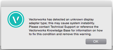
Vectorworks has detected an unknown display adapter type...
joelhufford replied to joelhufford's topic in General Discussion
Should anyone come across this thread in the future, be sure that your display is not configured to run 10-bit color by way of a SwitchResX Control Panel...Vectorworks does not like it at all. Switching back to 8-bit color from the short cut menu (millions of colors) appears to have resolved this issue.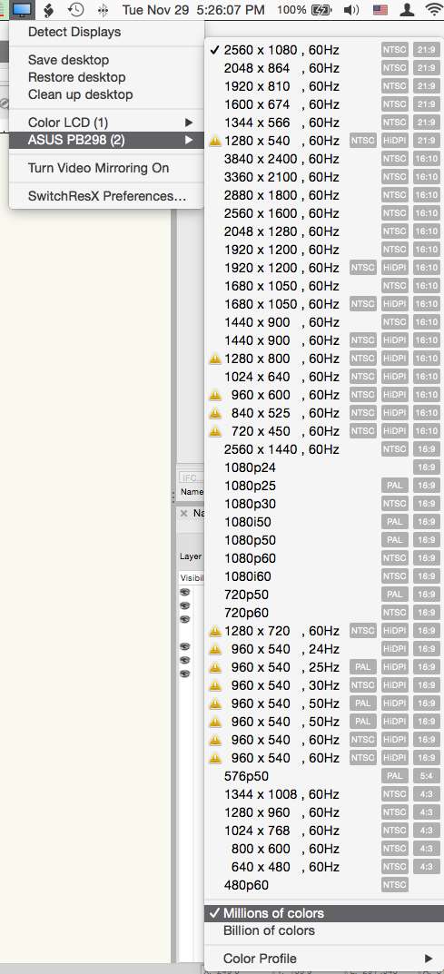
- 1 reply
-
- 2
-

-
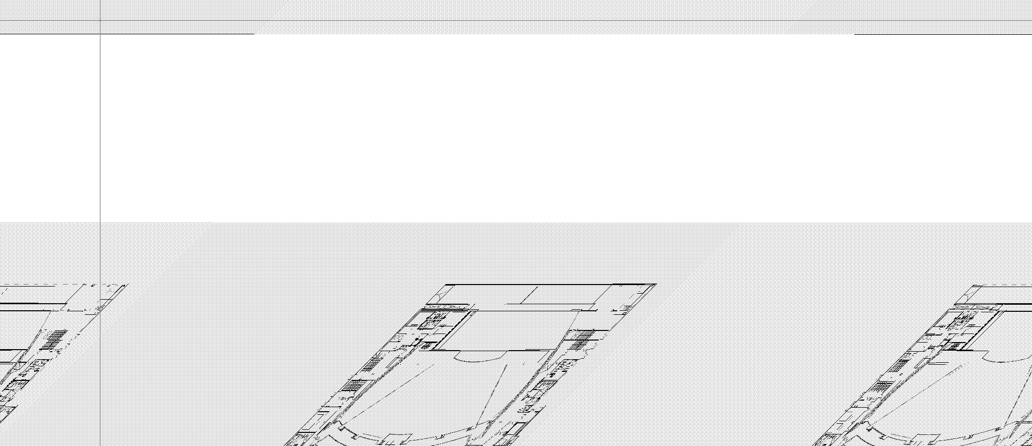
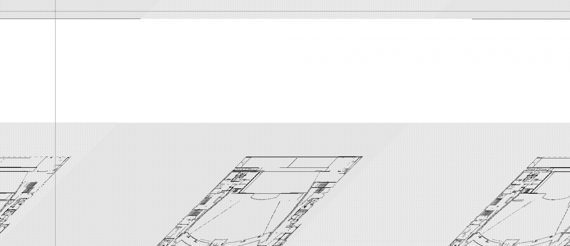
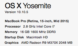
I continue receiving this message when firing up Vectorworks 2017 and 2016 on my MacBook Pro Retina running 10.10.5. All of my drawings now look like the second screen shot and Vectorworks has effectively become unusable. Anyone else experienced anything like this before? All of my googling has only discovered help for people using HP computers, not macs. Thanks, Joel
-
I'm wondering if anyone else is using Box.com as a platform for 2016 Project Sharing and if so, if you're experiencing the same issues with Box duplicating the Project File with user names append to it every time you commit a change? Seems like this makes Box unusable with Project Sharing and I don't see anyway to modify the behavior. Is there something I'm doing incorrectly? Image attached below showing the duplicates. It appears that changes made in my working file are only registered with the latest duplicate project file. Other users opening the original project file don't see any of my edits, even after a Save and Commit command. Google Drive appears to be working correctly for us now, but I was curious if anyone else is experiencing this?
-
Pat, That is awesome. It's exactly what I needed! Thanks so much!
-
For anyone tired of fighting the palette layouts when switching between different monitor setups, I wanted to share the success I've recently had with a program called Stay. https://cordlessdog.com/stay/ It's only available on Mac OS X, but it does a great job of restoring palette locations when switching between multi display setups. Just layout your palette positions the way you want them, and then tell Stay to record the positions. The next time Stay recognizes that monitor setup, it restores the layout. This works across every application on the computer, but I'm currently only using it for VW2015 and so far, it's been awesome.
-
Hi, Wondering about something I'm running into in VW2015 - although I expect this happens regardless of which version you're on. I'm cleaning up a drawing and when I go to delete a class that's no longer in use, occasionally I'm shown this dialog box. [img:center]https://www.dropbox.com/s/2yns4hfspseu5dn/deleting%20classes.png?dl=0[/img] So I'm wondering if there's a quick way to have Vectorworks tell you how many objects are currently assigned to the class? Using a custom selection of this old class, as well as the visibility tool to temporarily make every class visible doesn't cause anything new to show up.
-
If you need something down and dirty, you could also just make a custom selection in the document, selecting an instance of the symbol you're wanting to count. The other suggestions are perhaps more thorough, however, if you're just wanting to find out how many of a specific symbol are in your current drawing, the custom selection option only takes a few seconds. Tools >> Custom Selection >> Select Only Hit Enter Select : "Symbol" >> "Is" and then a drop down box allowing you to choose the symbol you'd like to select. The Advantage (or disadvantage depending on how you look at it) is that this will only select symbols on the active design layer. To search through the entire drawing, make sure you've selected "Show/Snap/Modify Others" in the Layer tab of the Navigation Palette. Just another way to skin the cat!
-
This seems like a simple thing... hopefully its something obvious that I'm just missing, but there are times I'd like to move the position of an element to a point in the drawing relative to the document origin, but the element doesn't have the option to modify the X, Y, Z coordinates in the OIP. Groups of objects are a great example of this. Is there a way to take a group or other element that does not have the X, Y, Z coordinates in the OIP and move it relative to the document origin? For example, in a front elevation, I'd like to take a group of 3D polygons or symbols, and move them such that the bottom of the group rests at 0' 0" off the floor. Hope that makes sense! Thanks, Joel