


LarryO
-
Posts
428 -
Joined
-
Last visited
Content Type
Profiles
Forums
Events
Articles
Marionette
Store
Posts posted by LarryO
-
-
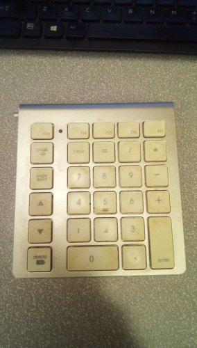
This is the device I was using. They probably don't make them anymore.
It was a big improvement in my workflow. I'm primarily lefthanded but use a mouse effectively with my right hand.
The ergonomics of an extended keyboard with navigation keys on the right almost requiring you to let go of the mouse to operate them is counter-productive.
-
 1
1
-
-
When I was using an imac and the keyboard without the numeric keypad. I was most happy with having purchased an inexpensive keypad that I placed to the left of the keyboard. It had the arrow keys, home, end and a forward delete. No longer was I bumping into an oversized keyboard with my mouse, nor having to release the mouse to press the navigation and view keys when my left arm got tired of reaching over to the right side numeric keys. And I now had an enter key on both sides of the keyboard even though there are some functional differences between return and enter.
I have been thinking and looking for reasonable priced option for scripted keys for some time. I recall when I first started drafting in the early 90's on Autocad that in addition to keyboard entry many workstations had a graphic tablet with a puck for input and those tablets had flexible and programmable menus. Plastic overlays to identify different functional areas. Menus that could change depending upon the current context or a modifier key was being pressed.
Somehow a lot of that functionality was lost or ignored when magnetic tablets went to the grave and these new touch screens simply have not caught up to the past. Or at least not within a typical workstation budget.
-
2
-
-
Thank Pat,
So for anyone wanting a look at what is possible with a little help from our friends here you can take a look at this Concrete Screw Anchor plugin script in VW2022.
I have a feeling that I may be a little weak in protection of attributes. I'm not sure if Push and Pop cover all the bases anymore.
Note there is some extra code where the use of RegularPolygon is concerned due to what I perceive as a couple of bugs. It doesn't produce a closed polygon, adds an extra point at the end overlapping the start point and it divides the input radius by 25.4 when the document is set to imperial.
Plugin goes in C:\Users\....\AppData\Roaming\Nemetschek\Vectorworks\2022\Plug-ins
Data file goes in C:\Users\....\AppData\Roaming\Nemetschek\Vectorworks\2022\Plug-ins\Data
So the caveat to using this is that the data file needs to be flushed out for the pitch and turn columns. I didn't have one of each of their sizes on hand here at the shop. The columns can be identified by the data structure note in the main file. Hilti's north american product offering is the product line I set out incorporate. It has a more simplistic shape than that of the Simpson's product. The latter having a tapered insertion end. I also believe Hilti's product is natively an imported metric product with a number of nominal designations for its imperial sales lineup. Hence why I used the metric system of measuring threads by spacing and not by turns per inch.
Have fun.
-
Thanks Matt,
I got it working!
I will PM you the result of my concrete screw anchor plugin.
The data file is a bit shy because the manufacturer (Hilti) that I attempted to emulate doesn't publish the thread pitch and number of turns of thread. I only had a selection of 1/2" profiles on hand and the pitch data listed in the file for the 3/8" diameter is from a different manufacturer (Simpson).
-
Where would I locate the setting that determines the LOD view when operating in the layer environment?
At the moment within my test file the visualization when in a layer is generating medium LOD.
-
Thanks Pat,
Upon a slower examination I did eventually notice them. By bad.
While I was able to implement LOD upon a completed object, I was not able to do so upon a subordinate object.
The solids operation continues regardless of these variables. The following operation completes the chamfer in all three settings.
After the step shown the washer flange is added via AddSolid. Looks like I may have to produce all three head variations and label them separately.
Don't suppose that there is an alternative approach that would permit the use of an IF statement to simply not do the chamfer before adding the washer flange?
Quote{construct bolt head}
BeginXtrd(0,ConstructionData.hh);
RegularPolygon(0,0, ConstructionData.hd/2, 6,2);
DelVertex(LNewObj,7);
SetPolyClosed(LNewObj,boolResult);
SetObjectVariableBoolean(LNewObj, 1160, FALSE);
boolResult:= SetEntityMatrix(LNewObj,0,0,0,0,0,0);
EndXtrd;
ResetOrientation3D;
Rotate3D(#0.000000d,#-90.000000d,#0.000000d);
hObjHandle1:= LNewObj;{chamfer bolthead}
BeginSweep(#0.000000d,#360.000000d,#10.000000d,0);
ClosePoly;
Poly(0,0,
0,ConstructionData.hh,
ConstructionData.hd/2,ConstructionData.hh,
(ConstructionData.hd/2/Cos(Deg2Rad(30.000000))), ConstructionData.hh-(((ConstructionData.hd/2/Cos(Deg2Rad(30.000000)))-ConstructionData.hd/2+0.5mm)*Tan(Deg2Rad(30.000000))),
(ConstructionData.hd/2/Cos(Deg2Rad(30.000000))),0);
SetObjectVariableBoolean(LNewObj, 1160, FALSE);
boolResult:= SetEntityMatrix(LNewObj,0,0,0,0,-0,0);
EndSweep;
ResetOrientation3D;
Rotate3D(#90.000000d,#-90.000000d,#0.000000d);
SetZVals(0,0);
SetObjectVariableBoolean(LNewObj,752,FALSE); {LOD: LOW setting, LOD variables (750,751,752) seem to default to TRUE}
SetObjectVariableBoolean(LNewObj,751,FALSE); {LOD: MEDIUM setting}
SetObjectVariableBoolean(LNewObj,750,TRUE); {LOD: HIGH setting}iResult:=IntersectSolid(LNewObj,hObjHandle1,hObjHandle2);
{add washer flange to bolt head}
BeginSweep(#0.000000d,#360.000000d,#10.000000d,0);
ClosePoly;
Poly(0,ConstructionData.fht+Tan(Deg2Rad(#16.8d))*ConstructionData.fd/2,
ConstructionData.fd/2,ConstructionData.fht,
ConstructionData.fd/2,0,
0,0);
SetObjectVariableBoolean(LNewObj, 1160, FALSE);
boolResult:= SetEntityMatrix(LNewObj,0,0,0,0,0,0);
EndSweep;
ResetOrientation3D;
Rotate3D(#90.000000d,#-90.000000d,#0.000000d);iResult:=AddSolid(LNewObj,hObjHandle2,hObjHandle1);
-
The context I have at the moment is I have been putting together some fasteners that are currently not represented in the VW package.
While the user will determine "size" and length in the case of most anchors there are a number of characteristics that are portrayed in association with each size.
Washer head thickness and diameter, actual shaft diameter, thread pitch, etc.
Are these measures best stored in a data file, hidden inside the script, in an attached string, or ?
Some of these are the result of calculations which scale based upon size but others are simply this size gets the same amount of threads as the last size or by manufacturer.
Is it good practice to permit user access to these characteristics? 🤔
-
omg! Thanks.
As soon as you mentioned Relative; I recalled that I had done this once before a few years ago. I think that I am missing the obvious path to finding out these basics.
I am always expecting the function and procedure reference to give me that insight into those basic aspects of the compiler but never find them. The old help used to have compiler basics in it but I'm not sure where it has migrated to these days.
I was fumbling around trying to close the result of RegularPolygon and was getting to the point of wanting a workaround by using polar vectors in the Poly procedure.
In the end I was able to figure out how to close the result of RegularPolygon and eliminate the extra point at the start vertex.
-
Why do neither of these Poly(); not create an equilateral triangle with 15mm sides?
first point is cartesian, second and third are intended to be polar.
d1:=15.000000mm;
ClosePoly;
Poly(0,0, d1,#0.000000d, d1,#150.000000d);ClosePoly;
Poly(0,0, #0.000000d,d1, #150.000000d,d1); -
Just a fly on the wall here.
You could you store a list of handles to the objects in question.
Create an empty list for handles to store the handles as they are sorted.
Walk through each layer comparing each handle to your first list of handles looking for a match.
When one occurs, transfer that handle to the second to the second list.
Once the first list is empty of handles begin your creation process by using the second list of handles that are now sequential.
Eliminates the possibility that adding objects is changing the hierarchy of objects, but places them all the new objects at the top end relative to all existing objects.
If the intention is to slip a copy immediately in front or behind the existing the occurrence to maintain relativity to existing non-selected objects as well I suspect you would need to maintain your own count of the number of comparisons made. Storing that location number as each match is made and then doing a LOT of forward or back movements as you create your copies noting that you probably have to increase the stored location number by the quantity of copied items at the moment each copy is introduced to the drawing file. I don't know of any other way to subvert the handler of the handles to reorder handles as one slips new items into the database of the drawing.
I have probably over looked something due to my limited use of VS scripting.
-
Thanks Pat,
Where do you find all these variables? Even knowing the number I cannot find them in the appendix listings delivered with VW2022 nor the developer section of vectorworks.net
I noted that they were listed as read only in that screen shot but in the other thread Julian and yourself were indicating that the values can be set.
So I am trying to determine if I need to read this value as a global setting and implement the degree of LOD or set the LOD to the items and the system displays them, or not, based upon LOD settings attached to each object created. <edit: I assume it is the latter.>
-
Is level of detail (LOD) implementation a subsystem operation or are there settings and flags that we can utilize to indicate or check upon for objects that need not be shown?
Some of the older fasteners have a user selection box to show or not show threads but that doesn't allow for displaying different scaled views with different LOD settings of a singular 3D assembly.
Any leads on implementing LOD within plugin object scripts?
-
Thanks Mat, Jonathan has so many good videos out that I wouldn't have found this one and known if it was applicable.
-
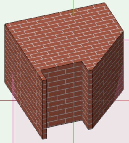
Do people produce these textures in Vectorworks?
Like this one that appears to be a flattened 3d elevation. When viewed in ISO it gives the appearance of concrete planters extending from the face of the brickwork.
Can a facade of windows be flattened to create a texture within VW's? Placing the texture on simple cubes for viewing from a distance for instance.

-
I started using the VW2022 install about 45 days ago. The minor menu differences is taking some getting use to and there have been some issues with crashing to desktop when interacting with the OIP and editing viewports, via mouse click stuff. Didn't want that while doing time crunch work.
-
Are there any visual (YouTube/VW_Univ) instructions for using the materials functionality?
What is the terminology (for editing etc.)? Like when one wants to change different faces of a generic solid modeled with flat surfaces.
I did this simple shape to try and learn this functionality of the program.
I checked the use material box and chose this default masonry pattern.
But to change the top to a solid green, like a parged coloured plaster or apply black to the alcove, like a soot appearance has fully escaped me.
What are the VWtools called for working with materials? Do they function on generic solids? Extrudes? Is conversion to some other type of solid required, a mesh?
-
Will uninstalling an old 2014 trial version of Vectorworks corrupt registered versions?
Specifically an old Toshiba laptop running Win10 (formerly WIN8.1) with VW2013 and VW2022 when using the instructions for "Uninstalling VW2015 and earlier"?
-
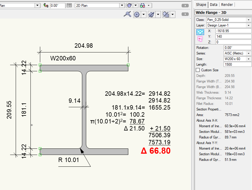
Yeah, It only amounts to about 110 grams now for a 6M length of average sized W200. Not enough to worry about anymore. There is more error in the steel mill manufacturing process than that.
-
Yes, I absolutely have made an error. I was using radius as Diameter.
20.02x20.02=400.8
10.01x10.01xπ=314.787
Δ 86.01
2914.82+2914.82+1655.25+86.01= 7570.90
against 7573.19 mm2
Δ
1.12.29 (I really need to use a calculator more often)Not as bad as I had figured.
-
1
-
-
I think this has been around for some time but I never needed accurate area calculations before so I didn't take notice. The calculation of polyline areas presented in the OIP is outside of standard acceptable tolerances. I only used the WideFlange because I was attempting to calculate weight when I noticed the error and that it was significant enough to alter the weight of a beam from which cost estimates are derived here in Canada.
Have I missed something???
-
Thanks @ Kazemester,
Hmmm, I took a look at the implementation this morning for a mechanical fastener. It would seem that this Ifc data is still very much a manual process prone to user error. As an example I created a 3d bolt using VW's Fastener tool. Then it was necessary to use "IFC..." tool on the instance but VWs is not yet filling in applicable fields with relevant data for the application's built-in objects. Minor description or object type differences or dimensional accuracy when keying in nominal length and diameter would cause the appearance of different products which are actually the same. Even the need for the document drafter to run the "IFC..." tool on each instance of a plug-in object and not have a global setting doing this for the for the built-in objects will result in errors for quantities. It would appear that utilizing Ifc categories for data storage to prepare material lists is premature, especially for small manufacturers such as ourselves.
-
Has VW presented, provided or adopted a framework for identifying materials and items?
Is there a list of fields that are be filled in when creating objects to be used in construction documentation?
I'm asking in the context of generating materials lists from objects found in the drawings.
Programs which are specific to the steel construction industry have these materials lists on every page that are loaded with items present on that page. They present quantities, sizes, name, standards and materials references, item source page and item destination assembly pages among other remarks.
So I was requested to see if I could build one of these materials lists that was not reliant upon manually typing up a list for each page. (Trimble does something along these lines with their Tekla product)
I believe this would require that the items in the VW document have an attached data record presenting consistent range of fields containing the enhanced details. Not wanting to reinvent the wheel I thought I would ask first before evaluating if this could be cost effective to attempt/implement my own take on the concept.
Thanks.
-
Yes you definitely have a few conceptual challenges.
You can create a Tool plugin that could capture the user's selection and create an object plugin. But passing a handle into a record's field attached to the plugin would not work for a permeant instance of a plugin because handles are temporary in nature. Object plugins being creation scripts would need to know how to recreate the user's selection or where to find a premade definition in order to display it. Objects the user creates are simply stored sequentially as a series of hidden commands written in a layer's definition. You would need to name an object with a unique name to reliably find it again and there is no guarantee it was not deleted or manipulated in some way. Capturing the user selected object and stashing it or copying it into a symbol definition created by a Tool plugin would be probably the easiest start. A symbol's name can be stored in a field of an Object's attached record for retrieval by the script of the object plugin.
You can think of a Layers, symbols and groups as containers, each with their own strengths and weaknesses, all three are parents to basic object creation commands.
-
Well that is puzzling. I guess I'll have to put in down to VW's export script function adding in extra code.
I drew the 3DPoly in a virgin blank file to see what the difference would be between a line drawn and a 3dPoly being drawn with a start point being 0,0,0 and end point being 0,0,1000.
Thanks.

Preferred font has too much spacing between words! tracking isn't the answer. help!
in General Discussion
Posted
I looks like you have 'Wrap Text' selected (fixed width) and 'Horiz Align' set to Justify.