


LarryO
-
Posts
428 -
Joined
-
Last visited
Content Type
Profiles
Forums
Events
Articles
Marionette
Store
Posts posted by LarryO
-
-
7 hours ago, Tom W. said:
Can you not just use the NURBS Curve Tool + draw the path as a single object in 3D?
Because I primarily use this for railings it is simply easier for me to produce the parts using predictable 2-d tools and then rotate the elements into their place and join them. Otherwise I am trying to figure out changing degrees where elbows are inserted among other things. its just easier to snap the ends together and see if the software can do the calculations for me.
-
My approach would be to draw the path along the floor in plan and then the vertical line in front view. Convert to nurbs, then compose to get the 3D nurbs path. You may have to add the vertical line after creating the extrude along path object by editing the path. Most of the time the nurbs path can be decomposed and the recomposed with the new nurbs line added. Aligning the end point is the critical aspect to the reformation of the path.
-
This happens in my work too, generally when there is a complicated viewport on a sheet, the page based symbols on the sheet freak out. Usually the graphic in our title block is the most distorted part. Save the file, then Revert to Saved resets it to normal.
-
 1
1
-
-
Excellent, thanks. I never would have come across that technique.
In the twenty plus years of using VW/MC I've never been the person producing walk throughs or rendered views.
-
Is there a pick method of realigning an existing viewport to an object's surface?
OR Can a custom viewport only be done in model space by creating an entirely new view port? (using pick method)
It is difficult to rotate the view if the object is sloping away from you because you cannot measure the angle. Assuming an edge is actually aligned with one of the prime (x,y,z) axes.
EDIT:
I used the edit design layer option to choose the working plane and align. But creating the viewport at this point is a bit disconcerting because it dumps you out of edit mode and onto the sheet where the viewport is being placed. Not sure if it alters the class settings or resets them. The latter being the default when exiting design layer edit back to a viewport.
-
Is there a development timeline for when we might see associative dimensioning locking onto 3D Loci and the vertices of 3D shapes?
This seems long overdue. I suspect that there must be data structure or copyright issues obstructing its implementation.
-
3
-
-
Then I would ask why the menu icon representing the rotation tool shows the arrow in a clockwise direction?
That would imply that a positive entry would rotate the object clockwise. 🤷♂️🤣😂🤣
-
1
-
-
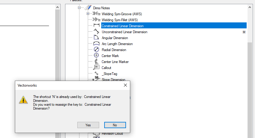
See photo. I had just reset the unconstrained to M because it has been toggling multiple view panes for some unexplained reason.
As you can see a number of the default tools that normally would have a short-cut key assigned are no longer assigned in this menu but they still respond to their originally assigned keys. Buggy.
-
Thanks Ray,
Just what I needed!
I simply didn't know which words to use to search for that function.
-
Is there a VS function that I'm just not seeing that changes decimal (a Real) to a character string in either fractional inches and or feet and inches notation?
I am hoping to present the value of an internal variable via a static parameter (String) in fractional inches or feet & inches if the user has selected that setting for their dimensioning.
-
Never mind, I found my bug.
Anyone high enough authority can scrap this message.🙄
-
HandletoObject1 := FunctionThatCreates3DObject(parameter1);
HandletoObject2 := FunctionThatCreates3DObject(parameter2);
Move3DObj(HandletoObject2, 100, 0, 0);
The parameter sent to the second call of FunctionThatCreates3DObject does not generate a 3D object and therefore does not return a handle to the variable.
The call to Move3DObj(); with no value assigned into the handle variable HandletoObject2 will move a 3D object that was created prior.
Is NIL a valid handle result to test for? Or would this work-around only work due to a fluke of luck?
IF (HandletoObject2<>NIL) THEN Move3DObj(HandletoObject2, 100, 0, 0);
<edit>
Actually it may not be a bug. The Function may still be assigned the value generated from the first call because the second call doesn't replace it due to the parameter in the second instance telling the function nothing is required of it. </edit>
-
Yes additional control point parameters only seem to appear when the plug-in is viewed top/plan.
I was hoping that in any ortho view they would appear.
I was going to reset the y-axis to zero internally each time so that it would only move in an x-axis direction for sliding elements along a linear plugin.
There being no Z adjustment was conceptually helpful.
-
Thanks Michael for the suggestion, that didn't make a difference.
I suspect that the control point parameter is only functional in Top/Plan view.
Too bad really. That seems to be the only interactive input with the object when using Vectorscipt beyond the pre-defined end points in the case of a linear object.
-
Is there any reason that Vectorscript control points would only be visible in Top/Plan view and not Front or any of the other ortho views?
-
As an anchor, an assembly sheet would typically display them between 1:5 and 1:12 but I've had to show them at 1:2 before.
As a tie rod the detail will not be as important as being able to record the parts in use and the threading required for each end. I'm not sure how well I'll pull that off the first try around but I got to start somewhere.
I am trying to think how a plugin could call up a texture if the texture/image was not already present in a drawing file. Would the image have to be in the plugin folder? I'm thinking first instance use in a new drawing file.
If this object was embedded into a base plate symbol under a steel column there could be hundreds of them. Granted the symbol will only be defined once but I can't imagine the potential lag if I don't drop the modeled thread detail at some level for something less GraphicProcessorUnit intensive.
-
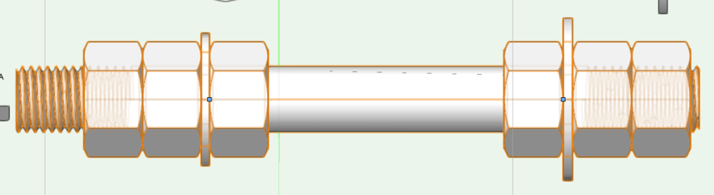
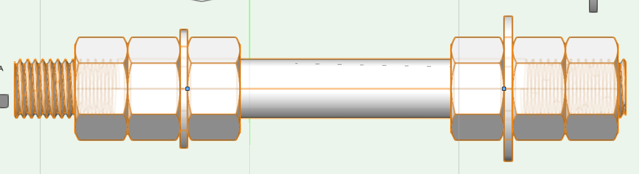
My PIO script assembles this object so far. A configuration useful for a common concrete anchor or a tie rod assembly.
Other than the rod, which it creates, the script is simply managing parameters, collecting data and then calling and placing the various built-in objects available to the VW_Arch and VW_Designer installations.
-
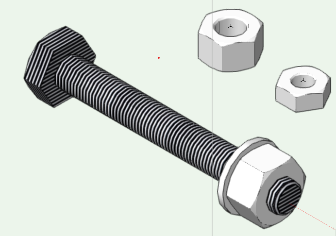
The image was my test subject for applying a texture. I took a 3D bolt with nut and washer and ungrouped them before applying a texture that approximates the look of threads. My own object is a simple threaded rod with various nuts and washers potentially at each end.
Seeing the texture wrap across the end of the solid was the part I'm not sure how best to eliminate.
I could slap a flat disk over the end and hope that it would mask the texture but whenever I've placed items in the same or nearly same location in the past the results were glitchy. Maybe a sweep to look like a chamfered end thrown on the end. Or would a tubular mesh be the object to use? I might be creating memory management issues. I don't know having not used them before.
Are sub-parts the place where a texture image would be embedded into the plugin definition?
-
I'm definitely starting from square one here when using textures.
Any suggestions for or against embedding a texture into a plugin object?
Any examples of the technique?
Are there any improvements in memory use or rendering speed by using a texture in lieu of actually carving out surface details such as threads?
How does one prevent parts of a solid from being textured? Like the circular end of this solid modeled to look like a bolt.
-
While I don't use that tool, it maybe taking a cue from the VW preference/Display/"Create text without fill" setting and incorporating embedded text with a background fill.
Change the background setting temporarily from None to Solid and confirm/change the colour to be white before changing the background setting back to None or ByClass.
Another technique with basic text blocks is to select all the text within the particular text block and then change the background to none. Text blocks support mixed point sizes and some other characteristics that would not be apparent when checking the text block's information.
-
I'm a bit late to this discussion, but if you still are interested. A 3D nut also gives one a look a method into using a sweep to tap a hole with threads.
If the Fastener tool exists in Fundamentals? Check on the show threads before ungrouping the plugin. The designer of this object used a two step approach for the hole so the detail level could be adjusted to show threads in hole, show hole or no internal detail.
-
1
-
-
The menu command Convert to Nurbs rejects a group as a valid input. So maybe the wording applies to some other situation.
-
The function reference suggests that a group of nurbs can be converted to a nurbs object.
Would it not simply be a matter of creating a 2d arc on a plane, rotating it, convert to nurbs, group the resulting nurb with the abutting nurbs and convert to nurbs again to produce the continuous nurbs object?? If it works in that manner you would not need to invoke the compose menu command. I didn't try it out myself. I just based the idea upon this statement from the Script Function Reference for the ConvertToNURBS function. It may not accept a handle to a group of nurbs as input. I think the only way for the result to be a group of nurbs would be for the input handle to somehow represent more than one object.
"Description:
This function converts the input object into a new NURBS object or a group of NURBS objects in the document."
-
Here are the menu icons that I forgot to load into the plugin before uploading the tool yesterday.


Graphic card whackiness
in General Discussion
Posted
Not so complicated viewport in this instance. I placed our marker symbol which is page based and that triggered the glitch.
Note that the titleblock is also page based. The plugin script places the symbol and then collects and manages the text.
Saving and reverting to saved will remove the ghost and fix the glitch which I am unable to capture using the basic screen capture method of Win 10.
Send me a PM if you think a copy of the file could be of assistance.
VW build 653494