


LarryO
-
Posts
428 -
Joined
-
Last visited
Content Type
Profiles
Forums
Events
Articles
Marionette
Store
Posts posted by LarryO
-
-
Thanks for the insight,
Not sure why there is a differentiation between 2d and 3d. Those textures create a realistic representation with an in depth implementation whereas the 2d fill is a nice basic colouring book approach to transparency. I thought both methods were implemented with either type of object 2d/3d just not at the same time.
-
 1
1
-
-
I created a quick corrugated profile and extruded it to the length required but could not get it to become translucent to represent a fibreglass panel. The profile is set to by class and the fill of the class is set at 25%. The extrusion is set to be by class.
Does this need to be a rendered surface to achieve this? (shaded will not work?)
-
That would probably require a script to check the specific variable(s)(a field?) for the stored value(s), whether it be "A", "S", "GA" or any other value and compare it to a table of substitution values which you have created. Then place the substitution value into the appropriate variable/field. Having not used the built-in titleblock functionality myself I don't know if the titleblock's code is setup in a manner that a variable's value can be replaced without interference or errors within the management code.
I wrote my own code for simplicity's sake to manage our own simplified titleblock. I placed it in the resource area if you're interested in scripting your own. Its a bit clunky because I didn't use any custom dialog or button functions.
-
23 minutes ago, E|FA said:
My reason for not using Materials is the fact that not all items can be assigned a Material.
You are correct; which is one reason we didn't adopt using them in 2019. HSS tubing, steel beam profiles, angles and others do not have the ability to assign materials to them unless they are embedded into a modeling process like addition, subtraction, etc., then the resulting shape will have the material check box available. That work around to get basic functionality for plugin like objects was simply not conducive to creating a clean model. Every time you do add or subtract, radius lines more often than not behave unexpectedly, even when the smoothing angle is set to 20° (normally it only needs 5°-7° to remove them).
-
Thanks Tom.
That material selection ability seems to have promise (I tried it initially in VW2019) but as you say that database doesn't seem to have mass or similar analysis data like heat transmission etcetera but seems to be built for presentation and rendering needs. Perhaps I'm not finding where these physical properties are or need to be??? I find the rendering data ok in the rendering tab, but no records are attached when selecting the material. I was looking to find a standardized nomenclature at least in which I could enter the values you say are missing. And I don't quite fully comprehend if this is an IFC task but I find understanding that structure to be overwhelming challenging to navigate for simply wanting to add mass etc. to the built-in elements. And there being no built-in tool for sheet goods every one of us would be starting from scratch for a plate of glass or steel or aluminum or ....
Larry
-
And a means for 3d elements to take on those qualities?
Like for an extrusion representing steel plate be able to report what it's weight is after having cut it into an irregular shape. And then be able to quickly switch it to aluminum, glass or even plywood for instance. Same with all the structural shapes built into the application, HSS tubes, Beams, Angles. To be able to select and report their material in the OI palette and volume/weight of the object created. That info being interfaced from a database in VWs just like the data of the shape profiles are currently taken from predefined tables.
-
1
-
-
I forgot to mention that the titleblock is just an ordinary autoscaling symbol. You can reorganize the elements and place new static elements. If you do not delete the existing linked text, these are elements that the manager maintains, but only move them around or change their characteristics you will not need to re-link the data fields to the text instances.
If I recall correctly the note option may not be fully embedded in the symbol. I added it much later in the script's development. The script will edit the default text's origin and move that text if the manual entry option gets too many characters; it shuffles left to accommodate as if it were right justified. That default origin I think I hard coded in the script giving you an opportunity improve upon my work. 😁 It shouldn't be too difficult to find and change. (Bad Larry, bad, cutting corners🙈)
-
Try separating the 2d and 3d elements of the symbol to give you some flexibility in rotating the 3d version.
Begin by making a duplicate of the symbol in the library. Go to the original symbol definition and removed the 2d elements. It will lose its hybrid status and become 3d only. You can now check the outcome and see if the results are what was desired. They can be rotated and flipped now but I personally would avoid extensive use of the latter if you intend to do a lot of edit in place operations. On a different layer keep or place an instance of the symbol in its natural orientation which allows for easier editing when everything is close to and at simple angles to 0,0,0 placement rather than trying to edit at various site locations, rotations and slopes.
Afterwards you can go to the duplicate and edit 2d mode, select all, exit, go to original, edit 3d mode, paste in place with wireframe active, probably plan view is best, and move as a whole the pasted objects relative to the origin if required or as parts to realign elements to the changes in the 3d object. Using the group command can come in handy here in case you want to re-select some of the 2d objects and not others. Ungroup afterwards. When you exit edit mode the 2d elements will automatically go to the 2d portion of the symbol definition if you do not change their Z values and the symbol becomes hybrid again when you accept the change dialogue.
-
In the second instance you are decreasing the accuracy in the file and there likely numerous points close together given the file size. Those points may now be perceived as being in the same location but in reality are not, just very close together. When calculating the object geometry potentially small surface triangles are no longer perceived as have a surface area and curves are not curved anymore, etc and would be causing geometric calculation errors like division by zero, etc. and they disappear or appear malformed with one or more points placed near infinity. Similar issues can occur when exporting to dxf/dwg if you don't have accuracy to at least 6 decimal places when using imperial units. If you have the ability to exclude small items from an import/export of a site it can help. Things like screws, faucets and floor drains that may have been imported from a manufacturers' library which were created with very high or very crude definitions. I've also seen company logos and converted font characters cause numerous problems when they were flattened and embedded into the file somewhere.
-
Are you certain that it is a "component" of an object that you wish to edit and not the 3d object edit mode that is applicable?
-
Something wonky with snapping and possibly related to the system tracks the cursor location has been occuring for a few generations now on the Win platform. As far back as VW2019 I think. But it was never something that could be captured to demonstrate. Like snaps functionality seemingly being disabled when in edit mode for 3d objects and sometimes all it took was to switch to wireframe and back to hidden or shaded and visa versa. Or trying to select objects in 3d edit where the object is visualized in one area but its edit nodes are displaying in another area.
And this may be something else all together, but after changing data in the object info palette the program not acknowledging short cut keys even though the enter key was used to terminate the entry and when one subsequently clicks on the main window if you don't select the window bar at the top the program occasionally locks up and eventually crashes to desktop or has to be forced into termination because it seems like the application is searching for an object that may or may not be in the cursor area. I'm guessing it loops through some code seemingly chasing its tail until it loses track of or runs out of memory. Could this also be related to the old auto-save bug where by when you tried to select too much while the application was initiating an auto-save a crash to desktop would occur??? Again I've never been able to capture the incident, only curse at it after losing 20-30 minutes of editing.
-
The lack of responses suggests this maybe a potential wish list item?
Or does the 3d pdf specification simply not include for "pdf Layer" functionality?
-
And if for some reason you need to rotate a hybrid symbol in 3d space and the tool says you cannot; begin edit of the 2d portion, select all, CUT to the clipboard, exit edit mode, there being no 2d elements the symbol will become 3d, now you can do that 3d rotation, return to 2d edit mode and paste in place, exit edit mode and symbol will revert to hybrid status. The caveat is, whatever you do, DO NOT do a copy or cut operation before "pasting in place" the contents of the clip board somewhere safe.
-
1
-
-
I would suspect that it was layered in Photoshop or similar editor. The detail of the building façade suggests a photo was used as a basis, considering how much out of proportion the other elements are it is unlikely a lot of effort was put into generating the building. Tiny people placed in front, a computer generated tree in front, probably computer generated the fence off to the left and the stepped ramp with railing is maybe from another photo. Shadows generated for the tree and one or two blurring techniques (probably not the correct name for the tool). Coarse for the added materials and a finer one for the initial photo. I think the people are too small compared to the building's window and the railing of the stepped ramp seems too tall. The signs are interesting details. Castle something or other, possible Street but I think there might be one too many letters on the sign.
-
1
-
-
I was able to generate the 3d pdf easily enough, but there were no options in the export function to address including layers or classes as layers in the pdf.
Bluebeam Revu didn't show any layers other than the primary layer but that was probably a default arrangement in Revu because there was no name applied to said layer.
-
As per the title, does anyone know if this is possible and what the technique might be for generating a 3D pdf with layers with classes representing those layers?
Larry
-
I was able to fix the problem easily enough by converting to 3d poly, ungrouping the result and then recomposing as a 3d poly line. At which point exiting edit mode changed the path back into a nurbs curve by the Extrude Along Path coding and the path was correctly rendered as straight segments.
But was using Compose to join those two nurbs curves an unsupported technique and the reason why it generated that amusement park railing?
-
44 minutes ago, VIRTUALENVIRONS said:
There could be a few reasons. Off the top of my head, I would go to the 3D Power Pack module and select rebuild curves. Rebuild will smooth out the curve. Add points if necessary.
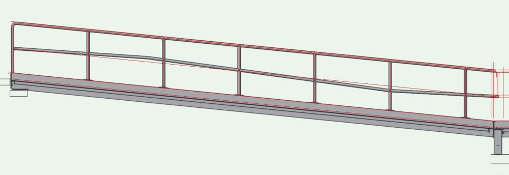
The wonky curving appearance is the undesirable amusement park look that was generated from the long straight segment of the path. The short 75mm horizontal segment at the bottom end is to transition the rail with a mitered look to horizontal, aligning the mid-rail with the adjacent landing's mid-rail on this ramp.
1 hour ago, cberg said:Just curious. Is your 3d conversion Res set to high?
Yes. And ortho projection.
-
These are some hints that I use to deal with the complicated aspect of internal origins and 3d drawing plane rotation of extrudes place all over a drawing environment.
Always try to layout the 2d geometry of an extrude at the layer origin 0,0,0 or in a logical relationship to x,y,z. ie centre a rectangle so the middle is at 0,0,0.
Rotate the 2d outline about the x or y axis if that makes for an easier use, prior to extruding it.
Pressing zero in the keypad twice while in extrude edit mode will reorient to the extrude's internal origin and go to wireframe.
Going to wire frame and back to shaded mode will often times (but not always) regenerate lost snapping points.
If it easier to generate the instance of an extrude at a particular location away from the origin do so but make a duplicate, edit duplicate and move geometry to a logical place relative to the origin, exit edit mode and move/rotate the duplicate instance into position over the original and then delete original.
There will be times where you have similar instances which in which symbols are not the solution. Like a post that varies in height with the same detailing at the ends as all other instances. You can place one end of the post profile at layer origin and your details as a symbol or extrude at each end and then group them. Once grouped move them into location as you would a symbol. Then anytime you want to add a particular aspect to all of these similar items that couldn't be represented as symbols you need only paste in place from one to the next. The pasted item will use the group origin as it's setting out reference.
It is good to understand that an extrude is 2d geometry laid on a flat 2d plane but if the geometry is rotated about the x or y axis, or raised/lowered away from z=0 before extruding it will become 3d geometry on a flat plane that behaves more like a 3d plane inside the extrude.
You can always use Set Working Plane and then Look at Working Plane to temporarily reorient the plane for easier rotations and if you use Set Working Plane a second time it is easier to choose a more logical origin on the reoriented plane from which to do a rotation, mirror or move.
-
2
-
-
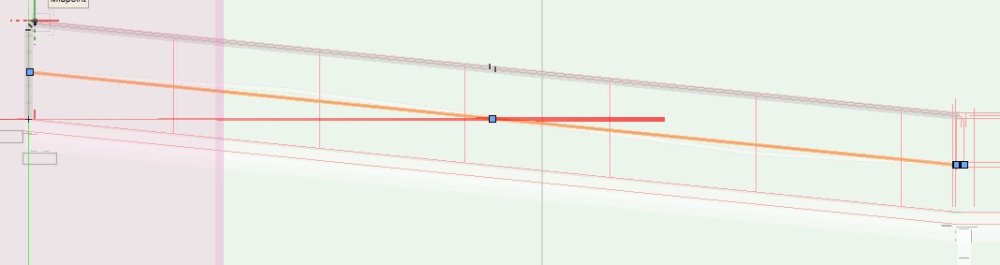
What is it that I am not understanding about nurbs curve pathing? There are two straight lines, one long and one short (75mm) at the terminal end. They were joined together as nurbs with the compose command and as a path look just fine but generate this wonky mid-rail as seen in the screen capture. Path is shown in the second image.
-
<edit: Can the default construction be changed to RH, so they don't have to be mirrored? Thanks.>
VW2022 SP6 (Build 679396)
-
place a callout with a single leader.
accept preloaded text.
change distance between text and leader's elbow. drag to lengthen.
double click to edit text.
cancel edit dialog.
try to undo change to distance between text and leader elbow. <ctrl Z>
callout becomes deselected and change is not undone.
VW2022 SP6 (Build 679396)
-
This might not be the answer to your issue (I don't utilize Renderworks for my work), but
have you checked the layer settings of the viewports in question? There is an override there to force B&W (or other colour/gray variations).
There is also the "Display planar objects" check box in OIP when a viewport is selected.
-
No, the first non-solid line type in a file will become the default line type whenever Line Type is chosen.
You can try and purge or delete all line types and then reintroduce the one you want as a default in your template file. It should then become the default after which you can reintroduce all the types you use from another file using cut and paste of an assemblage of all the examples. At least I think this technique still works.


Are rendering remnants normal for 3D views?
in Troubleshooting
Posted
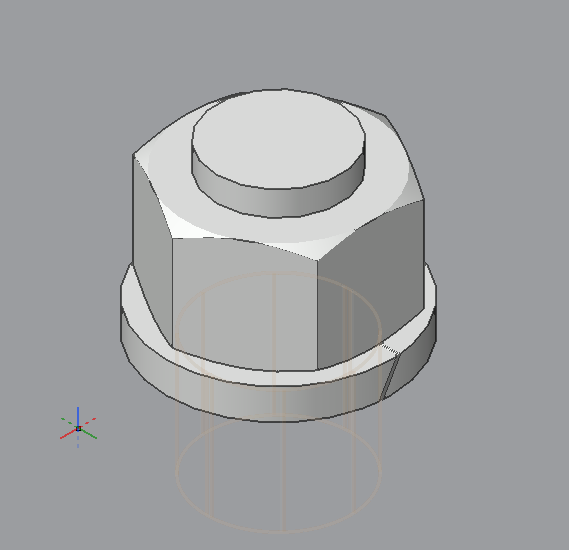
I would be ok with turning off the threads if that would help but the shaft tool doesn't seem to be set up to respond to the level of detail settings.
And there is no obvious means to show/swap a simple round extrusion for the shaft using those settings either.
So I am guessing that it is either all or nothing, no visual reference when dimensioning if they are not there at all. ☹️
And those remnants place dots on the "Hidden" rendered side views when printed. The thin pair of line one sees in that side view is me trying to mask off what I believe is a radius demarcation line in the same location as a hidden perpendicular face; neither of which should be showing.