


LarryO
-
Posts
428 -
Joined
-
Last visited
Content Type
Profiles
Forums
Events
Articles
Marionette
Store
Everything posted by LarryO
-
Lost my original account sometime in the late 90's when it was still MiniCad. I couldn't remember which email account I had sign up with. I was kind of wierd searching for myself as a different user when I wanted some applescript/vectorscript that I had shared with the community way back. Postings since lost to updates and change overs of these forums/bulletin boards. Its possible that I maybe on my third profile now, hehe. Happy Bronze Anniversary Mickey! (belatedly)
-
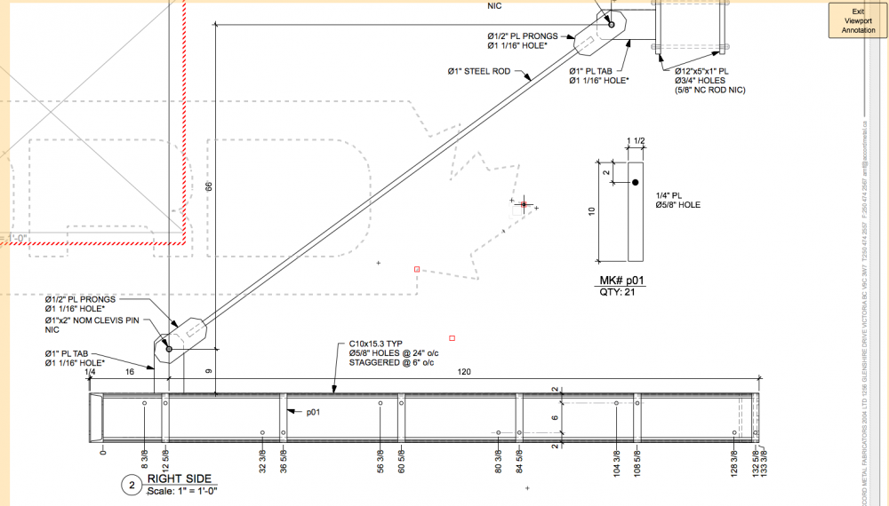
Show snap modify is definitely the setting for both class and layer. The view is 2d plan and wireframe. The objects are polylines, rectangles, circles and dashed lines. The orientation is such that the polyline appears to be a stair stringer form from steel channel with rectangles forming the mounting and closure plates at both ends and two parallel rows of circles solid black representing holes in the steel. The stringer is drawn at the intended slope in the design layer space and the viewport is rotated in the sheet space so as to show the steel horizontal. At this point the stringer is dimensioned with the constrained linear dimension tool in ordinate mode, typically from left to right. I've grown accustomed to the circle snaps rotating away from vertical/horizontal but snapping to the polyline when grouped frustrates me to no end. An additional note is that the paired circle is also embedded within a symbol which representing instances of bolted in treads. Snaps do not include grid, distance, smart edge, nor tangent, the rest are active. All object points active, no datum functions, nor extensions from smart points and alternate coordinate system off. Most of the time the sequence in which I do the tasks things go smoothly, but not snapping occurs enough to be frustrating. I'll turn on the ques for a time to know when and which snaps are/are not operating.
-
This is a long standing frustration that I have encountered over the years from the versions of VW with viewport functionality. I cannot snap to items that have been grouped in the layer environment when dimensioning them in viewport annotation mode on a sheet. What am I missing? I group items to assign the groups visibility classes for use in viewports while the basic components are assigned to classes that control lineweight, colour, linestyle, etc.
-
Best Wishes! and good luck with your goals. I have appreciated all the efforts that you and your colleagues have contributed to. Larry
-
I'm not familiar with the ASUS set up but with the Toshiba laptop I have the NVIDIA processor cannot drive the built-in display. Its set up to drive the ports for external displays.
-
Thanks Kevin, That definitely makes modeling with those 3D steel shapes more useful. Its definitely easier to add missing lines than to remove the undesirable ones.
-
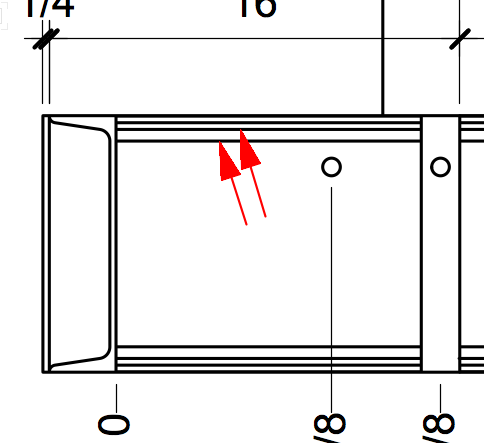
Has anyone found a means to reduce the line weight of radial start and stop edges when utilizing the 3D objects for 2D drawings? I show such an example here where 2D drawing standards would not show the lines indicated by the red arrows or they would be extremely faint. Instead all lines are illustrated using the edge profile weight. Secondarily I would like if it was easy to render voids in the material black. I've tried black circles placed within the opening but the fill colour doesn't display when using hidden line rendering and we don't want the shadowing created with OpenGL.
-
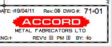
Here is one that the team probably did not anticipate when programming. I have an in house developed titleblock plugin that inserts a titleblock symbol which is of the 2D page based type, not world units. #1 When I am editing annotation in a viewport which is on a sheet along with the titleblock plugin we get the following occurring. And being able to snap to the enlarged shadow of the titleblock plugin. #2 When one exits the annotation environment of the viewport the titleblock plugin boundaries are much bigger than the symbol within. The size difference is the scale factor (1:12) of the recently edited viewport. After editing the instance (changing some aspect in the object info palette) of the plugin its bounding box returns to correct size. I've attached a screen shot of the ghosting taken in annotation mode and of the portion of the titleblock seen. The D of ACCORD which is not text but a polyline with red fill.
-
Thanks Bruce
-
Does anyone know if character stacking is possible or not in VW2019? OS X Going back many years, some programs and certain operating systems had a means to type one character over the other without deleting the first character. You could type the box glyph, then press the backspace key (the key did not function as a delete command it simply moved the cursor back a space as the name implies), then type a check mark glyph and the display would show a checked box. You could type "xxxxx" or em dashes over top of an existing string of characters, without having to align two independent text boxes.
-
Thanks Guys, when the office finally gets my new workstation purchased I think I will invest a little more time fixing the script behind the company's titleblock. The Python call sounds like something worth figuring out. Its always been a pain making two subroutines simply because the data arrives differently between MAC & PC's. The next task after this is to hopefully get a few more Unicode character glyphs printing on the new PC's. I'm losing my MAC in the upgrade but gaining VW2019. For some apparent reason boxes, check marks and almost equal were easy to type and print on the MAC but seemingly impossible on a PC running VW2015. check marks would display but never print and I couldn't even get my PC laptop to display almost equal in VW2013 dimensions.
-
is there a way to add the current date into a drawing?
LarryO replied to Stephen M.'s topic in General Discussion
You can also write a vectorscript and/or python script to read the system date and write the date to a linked text field in your own symbol. A plugin can insert an instance of your symbol and then write the date data to a predefined field in your symbol. -
Has anyone else noticed that with VW2019 that the separators on the Mac platform have changed from forward slash "/ " to hyphen "-"? Also Date(2,0); VW2019 generates yy-mm-dd where as VW2013 generated mm/dd/yy on the same MacBook Pro. Did the function get tweeked to generate the same output regardless of MAC/PC platform? If so, would have been nice to also make the month and day always generate 2 digits. PCs generated hyphens and MACs forward slashes. I don't recall it ever being system setting sensitive but it was definitely platform sensitive.
-
I can't see how RunTempTool could work. One has to pass it a Function and GetPt and GetPtL can only be called from a Procedure. I experimented vstGetPt2D also choosing index #0, 1 and 2. Zero returns the world coordinate point for the PIO origin and one returns the second world coordinate point of the linear PIO. Two returns garbage, not the control point location. I do not think that these user interactive calls can work in a linear PIO. Once the PIO environment is created they crash and burn because they seem to be seeking information from the world environment that is somehow not available to them anymore. So it would seem that I am stuck with what I have or taking some lessons on creating a custom tool to collect three points then call the linear PIO and somehow pass the values onto the procedure. While still permitting the procedure to act alone in regenerating itself after OIP changes and dragged point changes. hmmm
-
Thanks Josh & Raymond for the assistance. I still have to tackle moving my control point into position so that it remains vertical to the origin in World space and making the code flip friendly. The latter I've done before so it will not be too much trouble. I still hope to figure out how to have GetPt retrieve values and pass them into a variable before the code finishes. It'll be such a pain if I have to deselect the tool every time to move the control point into position (it identifies the upper boundary of the pickets) and then re-select the tool to draw the next set of pickets. This is a functional result, but has limitations. Only works from left to right ATM. It still has fluff code in it and some clarity formatting was lost during pasting. Procedure Picketeer; VAR PIO_Handle,PIO_ParentWall,PIO_Record,hLine1,hLine2: HANDLE; PIO_WorldOrigin: POINT; PIO_Rotation,rOffsetDistance:REAL; iAccuracy: INTEGER; Quantity: LONGINT; PIO_Name:STRING; Bool1:BOOLEAN; cpLocation,cpDestination: VECTOR; {This Function may be required during improvements, leave in} Function HDuplicatePolar(H :Handle; Dist, Ang :Real) :Handle; { Same as HDuplicate() using POLAR coordinate input } Var V :Vector; Begin V := Ang2Vec(Ang, Dist); { convert polar to rectangular} HDuplicatePolar := HDuplicate(H, V.x, V.y); End; { Function HDuplicatePolar} BEGIN PushAttrs; FillColorByClass; FPatByClass; PenColorByClass; LSByClass; LWByClass; MarkerByClass; OpacityByClass; {initialize required variables' values} Bool1:=GetCustomObjectInfo(PIO_Name,PIO_Handle,PIO_Record,PIO_ParentWall); GetSymLoc(PIO_Handle,PIO_WorldOrigin.x,PIO_WorldOrigin.y); PIO_Rotation:=HAngle(PIO_Handle); {IF GetPrefReal(152)=1.0 THEN iAccuracy:=4 ELSE iAccuracy:=0;} {imp vs mm, currently not req'd} cpLocation.x:=PControlPoint01X; cpLocation.y:=PControlPoint01Y; cpDestination:=Ang2Vec(PIO_Rotation, PLineLength); Quantity:=0.5+(cpDestination.x+PPicketSize)/(PMaxGap+PPicketSize); {includes final picket which is replaced by next post} rOffsetDistance:=(PlineLength+Ppicketsize)/Quantity; {centre to centre picket spacing} MoveTo(0.0,0.0); {creating first picket} LineTo(0.0,NORM(cpLocation)); hLine1:=LNewObj; HRotate(hLine1,0,0,-PIO_Rotation); {orient first picket line vertically} hLine2:= HDuplicate(hLine1, -PPicketsize/Cos(Deg2Rad(-PIO_Rotation)),0); Hmove(hLine1,rOffsetDistance,0.0); {Move first pickets into place. Could have started at this location instead of orgin.} Hmove(hLine2,rOffsetDistance,0.0); {Easier debugging of flip & rotation issues} While (Quantity>2) Do {place remaining pickets} BEGIN hLine1:=HDuplicate(hLine1,rOffsetDistance,0.0); hLine2:=HDuplicate(hLine2,rOffsetDistance,0.0); Quantity:=Quantity-1; End; PopAttrs; END; RUN(Picketeer);
-
The pickets are only a series of lines on the slope of the rail. I group them when drawing them manually. So I am capturing 3 points and pre-setting picket diameter and max gap values. The nature of doing shop drawings, updating for site measures is that I created a tool which defines the measured stair with only two points and a few pre-set building code defined values; drawing in top and bottom rails that can be traced over or used as is. Then we manually place posts due to the variety of (un)suitable anchoring conditions, locations and styles that seem to occur within a single flight sometimes. And finally draw in pickets where required on a separate layer to make them print grey). So I am finally getting around to making a plugin to automate the task of calculating quantity and then spacing them equally along the incline of the rail. Hence my desire to simplify it all down to a three point task (2 steps) from what is currently about 12-14 steps if one does them in the correct order. I'm sure that the SetRField works as you say it does; I just have a problem mixing up strings and character arrays all the time. ATM I am trying to decide if I should Create the first line and copy along the incline or or draw along the axis and rotate them all into position. The latter is how I approached the stair tool because HDuplicate(objecthandle, distancevariable, # anglevariable d); fails. The angle mode indicator # does not appear capable of accepting a value from a variable. So much simpler if Polar vector variables were an option.
-
I've had issues with using a variable in the name location of SetRField so I've always typed it in. The thing is that the control point is not moving to the user selected point location. I suspect GetPtL is not capturing values during first pass. The control point remains at the default location set by the parameter default values. The exercise here is an attempt to have the control point set during the first run (placement) of the plugin and not have to drag it over to the correct location afterwards.
-
I would guess from what I have observed is that GetPt and GetPtL are not suitable for inside a Plugin object (VW2013). This will display the Message and draw the Line and request a point from the user. Bool2:=FALSE; IF IsNewCustomObject(PIO_Name) THEN Bool2:=TRUE; IF Bool2 THEN Message(cpHeight.y,'x',bool2); IF Bool2 THEN GetPt(cpHeight.x,cpHeight.y); MoveTo(0,0); LineTo(0,0); This will draw the Line and request a point from the user, but not display the Message. Bool2:=FALSE; IF IsNewCustomObject(PIO_Name) THEN Bool2:=TRUE; IF Bool2 THEN GetPt(cpHeight.x,cpHeight.y); IF Bool2 THEN Message(cpHeight.y,'x',bool2); MoveTo(0,0); LineTo(0,0); This will draw the Line and request a point from the user, but not display the Message. Bool2:=FALSE; IF IsNewCustomObject(PIO_Name) THEN Bool2:=TRUE; IF Bool2 THEN GetPt(cpHeight.x,cpHeight.y); MoveTo(0,0); Message(cpHeight.y,'x',bool2); LineTo(0,0);
-
Some curious activity happens with this preliminary scripting. Testing units are mm. Message screen is displayed before closing plugin's default record initialization dialog. Message screen is updated to reflect changes in default record initialization dialog before GetPtL point has completed selection. GetPtL doesn't save value of point selected. Zero is being displayed as value stored in cpHeight.y And finally ControlPoint01Y is not being overwritten with the value in cpHeight.y. (perhaps cpHeight.y is NIL and not zero, but Message displays 0 and not NIL) What am I not understanding? VAR PIO_Handle,PIO_ParentWall,PIO_Record: HANDLE; PIO_WorldOrigin: POINT; PIO_Rotation,rTemp:REAL; iAccuracy: INTEGER; Class_Name,PIO_Name:STRING; Bool1,Bool2:BOOLEAN; cpHeight: VECTOR; BEGIN PushAttrs; FillColorByClass; FPatByClass; PenColorByClass; LSByClass; LWByClass; MarkerByClass; OpacityByClass; Class_Name:=ActiveClass; Bool1:=GetCustomObjectInfo(PIO_Name,PIO_Handle,PIO_Record,PIO_ParentWall); GetSymLoc(PIO_Handle,PIO_WorldOrigin.x,PIO_WorldOrigin.y); IF GetPrefReal(152)=1.0 THEN iAccuracy:=4 ELSE iAccuracy:=0; IF IsNewCustomObject(PIO_Name) THEN BEGIN GetPtL(0.0, 0.0, cpHeight.x, cpHeight.y); SetRField(PIO_Handle,'_StairOutline','ControlPoint01X',Num2Str(iAccuracy, cpHeight.x)); SetRField(PIO_Handle,'_StairOutline','ControlPoint01Y',Num2Str(iAccuracy, cpHeight.y)); END; MoveTo(0,0);LineTo(cpHeight.x,cpHeight.y); MoveTo(0,0);LineTo(600,0.0); {ResetObject(PIO_Handle);} Message(PControlPoint01Y,'x',cpHeight.y); PopAttrs; END;
-
Plugin w/Height, Direction & Distance (polar vector)?
LarryO replied to LarryO's topic in Vectorscript
Sounds like a control point is the way to go. I'm spacing pickets between two posts of a sloping guardrail on a frequent basis. It is much simpler to graphically determine the height between the top and bottom rails than it is to calculate it. Same goes for the slope and linear path. We've currently got a reasonably quick manual strategy but it requires about a dozen steps for each panel, each time there is an adjustment to the guardrail. -
Plugin w/Height, Direction & Distance (polar vector)?
LarryO replied to LarryO's topic in Vectorscript
Thanks for a quick response. I'm wondering whether a control point might work in lieu of a third point during placement. I've not used them before so I will have to experiment first I guess. I can't seem to find the Wiki you mention. My google searches kept winding up at developer.vectorworks.net main page. -
Just speculating here, but could these be record definitions and not actual records. When you go to the data tab of say a symbol and there you find record definitions which can be associated/attached to the symbol by checking the adjacent box. When you search for records it will seek and find the ones attached objects and from there you can extract the stored data. But the definitions themselves contain no data other than their format and are stored in another place much like symbol definitions waiting to be copied and attached to some location on (or in) a layer.
-
Has anyone got an example of a plugin which requires three points of input? Is there a means to limit the 2d path object to only three points of entry, without the user having to do double click termination? I wish to place posts along a straight line path and enter height during the placement. First point = origin / start point Second point = direction and distance(magnitude) Third point = height from one of the other points, preferably the origin
-
Units...need more control
LarryO replied to ericjhberg's question in Wishlist - Feature and Content Requests
I don't know much about the grade objects functionality, but with dimensions you utilize a dual dimension style, set the secondary units and suppress the display of the either the secondary or primary units. I've used this where both metric and inches were required in the document. Normally I'm only suppressing the secondary units; fractional inches require too many characters to communicate small values. -
Do you not require a single period or double period before the slash. Single period representing the current directory and double period meaning go up one directory level. Also is the mac platform freed from activating Unix escape sequences (like \n ) when utilizing back slashes? You might need \\ to break the escape sequence. I'm no guru when it comes to Unix but I just read about this potentially being a problem when scripting. Of course one cannot span drives when using relative paths; only the active drive is accessible.


