


LarryO
-
Posts
428 -
Joined
-
Last visited
Content Type
Profiles
Forums
Events
Articles
Marionette
Store
Posts posted by LarryO
-
-
Here take a look. not much to see anymore though.

-
What do users of the PC (Win10) version of VWs use to insert a Carriage Return/Line Feed into a field box of the OI palette?
On the Mac I was using I could simply write my text using the text command and create a second line with the return key, copy into the clip board my two rows of text complete with the invisible CR/LF control character and paste it into one of the detail tag's title field and two rows of my text would appear above the tag's horizontal line. But all that emerges when I paste on the PC is the characters before the CR/LF; everything afterwards is missing.
Existing tags with two lines of text created on the Mac display on the PC correctly and you can edit the regular characters either side of the CR/LF but you cannot paste the sequence of visible and hidden characters into another detail tag. Also noted that the info palette doesn't do a CR/LF in the field box on the PC whereas the MAC does.
-
Does anyone know if there are run-time/visual basic/c+libraries or something similar required for the Navigation palette to operate? The Navigation palette in my Win10 PC installation of VW2013 has stopped displaying the classes and layers of the open document. I'm wondering if an update pushed from Microsoft or Steam has removed or changed a required piece of software that supported the palette's functionality.
-
Excuse my ignorance if what I'm about to write doesn't apply to DLVPs, I don't (Xref) reference in outside documents/layers in my VW's work.
Now what I was thinking is that the technique of group, copy, link/turn on layers (see below) may work in a similar fashion with DLVPs but by linking the original file's layer into the DLVPs that have been copied over to a layer in the new file. You could then un-reference them as suggested by Tamsin and copy the result back to where you need it. You probably need to save the new file at one point and revert to saved before unlinking the referenced layer(s). This would allow VW to properly load the DLVP data and links before attempting to 'explode' it.
I'm still not sure that this un-referencing Tamsin has suggested will actually create what you are seeking. Yes it should bring in all the geometry into the new file on a layer but I think you were wanting to create an instance(copy) of the geometry but only that which is showing in the cropped area in lieu of the viewport at the viewport's location. There maybe a technique/command for that process too but I'm not familiar with it.
Technique: With regular viewports on sheets the application generally prevents one from copying them to another file by popping up a message whenever one trys to do so. But if you take a blank file or existing one that has the same class structure(colour/LW/etc), you select the viewport(s) and group them. Copy to clip board. Paste in place in the new file on a sheet. Ungroup, copy over the line work from the original layer(s) and paste them in place on layers in the new file, edit the viewport layers to turn on the respective layers. They should now be showing evrything as before but in the new file. Now the important step. Save the file and then revert to saved before doing further editing using the viewports interface to access design layers.
-
Update: The issue with snapping doesn't seem to be file specific. Viewports on the same can be responding normally while others will not snap to points. This morning the problem I had yesterday in one viewport went away and showed up in another. Shut down the application and relaunch and all viewports with snapping failures are now responding normally, until they don't again.
-
That CadMouse does seem to be an improvement over my favorite, Razer's Death Adder (not wireless). I've had days where my scroll wheel finger has gotten muscle stress from pushing down and holding that button too much, which I lay blame on Adobe's Acrobat products and their panning technique. I've only worn out one Razer mouse in over five years. Possibly too much dirt or film build up inside made for unresponsive movements and jumpy scroll wheel. Oddly enough the worn out one continues to function when used with a mouse pad.
-
Does anyone else experience this problem. I cannot seem to get dimensions or lines to snap to any points associated with objects that have been grouped. Specifically the group of objects are on a normal layer and I am attempting to dimension to them while working within a viewport's annotation environment.
I'm thinking that it must be some sort of setting that I'm overlooking because I cannot replicate it this evening on VW2013 here at home. This was happening to me on VW2019 at work. Both are Win10.
While I'm here what could cause the navigation palette to stop showing the document's classes and layers? VW2013-Architect, Win10
-
Thanks @Jeremy Best,
I'd forgotten about that extra functionality of preview.
Unfortunately only a very small proportion of the pdfs we receive have their layer data exported. Whereas with a nice crisp image I can erase to my heart's content any undesirable content in a paint or Photoshop program. Acrobat has been a sort of nemesis of mine for years. I don't imagine I'm alone in saying that I can rarely recall how to locate and change various settings for the tools without google searching. Calling it an intuitive interface would be giving it praise from my experiences using it. hehe.
Alas I handed off my 8 year old mac just last week to the junior draftsman in favor of an HP with a graphics processor that doesn't bog down regenerating views of 3d canopies.
-
This is a classic case for BIM integration.
The information / data that everyone is referring to is stored in a record attached to the building object (in this case a door) not the display object (a tag).
The BIM data can then be accessible to worksheets and any variety of customizable tags (a plugin object which incorporates a user defined symbol with linked text and transfers data from the building object's record to the display object's record of fields).
One possibility is: the user creates their own page based symbol laying out the tag with text, linking each text to a field in an attached record. The symbols' field names match the field names contained within the record attached to the door object. If you don't want a particular piece of data in your custom tag you don't include that field name in your symbol's record. The tag creator also includes two additional fields in their symbol's record, one which utilizes a pre-defined (field) name that the Placement Tool identifies with which contains the name of the record or plugin object the Placement Tool would search for in the object ('door-record') you attempt to associate the tag with. And a second field which stores the unique 'serial' number of the door object (in this scenario). This serial number is essentially a permanent handle which is created and stored in a door object as part of the BIM information. The Placement Tool would request the user to select the desired tag from a tag list which the tool has created by searching the symbol library for symbols containing the pre-defined field name. The user would then attempt to select the object (a door) to link their tag to and then click where they want the tag placed. Any number of tags can be placed where ever the user desires and they link to the unique door instance. Update that instance and all tags linked to it have the ability to refresh their information. An alternate function of the Placement Tool could be to select the object (a door/a window/a cabinet) and the Placement Tool would then place the selected tag at every instance of the object which appears upon the layer which the selected object resides at the origin of each instance object. The challenge I see is ensuring that whenever a door object gets created, duplicated or pasted that it checks for the preexistence of its serial number and changes itself to be unique. And whenever a referenced object is deleted that the tag(s) linked to it realize their source is missing and delete themselves too.
Actually I guess it would be the plugin instance which generates the symbol and loads it with data from the object that would have to store the serial number of said object; not the symbol object's record because the symbol gets reinserted and regenerated with each refresh of the plugin. The Placement Tool would set the initial serial number data into record of the instance of the tag controlling plugin.
This is similar to a titleblock plugin I created that utilizes a page based symbol for layout and a special instance of itself for maintaining the same project name, client name, and project number through out a file. The plugin looks through all instances of itself for the flag that identifies the special primary instance to copy data from. If it doesn't find one it checks what sheet of layer it has been placed upon and compares it to a string contained in its script's definition. If the string matches the sheet name it changes its own flag to identify itself as the primary titleblock and makes those three fields visible for editing in the info palette. It works pretty slick because if you copy another primary titleblock into a file with an existing primary the regen process allows the script to turn off the flag of the instance being copied in and if the copied instance doesn't find an existing primary it is going to check if conditions are right to make itself the primary which retains the data brought over from the other file.
But first Nemetschek is going to have to fix the scaling bug associated with page based symbols that are outside of the viewport being edited. When there is an instance of a plugin which is placing a page based symbol on a sheet and you are in annotation edit mode of a viewport also on that same sheet that symbol instance gets rescaled to the viewport's scale instead of maintaining the scale of the environment in which it is placed. It would drive one bonkers if there were more than one or two instances of the plugin on the sheet with all those useless snap points of the symbol instance potentially behind the view port you are attempting to add annotation to.
-
That is a shame. The pdf image before ungrouping is so much crisper and defined than the bmp created from it.
I imagine there are other tools outside of VW that can create a quality raster image to permit editing out of extraneous data from a background plan.
-
I didn't get any responses when posted to General Discussion. Re-posting here as I couldn't figure out how to move the original post to here.
It is frequently desirable to import a PDF to use as a background for locating our work in a building.
For reasons of liability and clutter we find it to be a good practice to remove all referencing and architectural items (millwork, furniture, hatching).
Are there any settings which can improve the quality of the image created when ungrouping the pdf. I find that there is significant degradation between before and after ungrouping. Low dpi and spray artifacts possibly from anti-aliasing are introduced. Alternately the line work extracted from the pdf loses its differentiating qualities that could have been utilized efficiently to delete clutter, etc.
Are there settings somewhere which can be utilized to reduce information and quality loss during PDF conversions?
-
Yes a script is the means by which you can edit one or many items of a selection set and change one attribute or many in a batched or singular edit. If you have a specific theme to your attribute edits this is a time saving method which is very similar to the attributes by class methodology. But if all you need is to do open and close the attribute pallet after making selections then simply enter the shortcut into the mouse key. If your menu doesn't have one already programmed then you need to edit the menu first and you may as well make it one of the multi-key finger stretching arrangements, shift control alt something that are less utilized
-
if you are in an infinite loop. This could be as simple as checking for NULL data from your read line request to determine EOF. I don't believe that files embed a readable ascii 4 character because EOF is a control state by definition.
-
Thinking aloud here.
Write a selection script to find the identical children, ignoring location, within the parent.
If VW does not give the the parts type numbers perhaps one can select one part and a script can identify and then flag selected all the other children in that parent that are the same size/length/orientation*. I guess the initial challenge is identifying what the program sets as selected (the child or the parent) and returns a handle to. *Do the children/extrudes have a common rotation like zero for horizontal mullions and ninety for vertical mullions.
I guess another possibility is that curtain walls are a table of parameters for the parts and a routine that generates the image. Hmmm there might be no boolean selection flag/bit as we currently understand for each of the children.
-
It is percentages expressed as a decimal between the witness lines but I can't recall if it is only positive percentages leading to or from the starting witness or if negative percentages can also be used and it is from the mid point.
-
See if this works for you.
Procedure kast;
VAR
a,v,l:REAL;
teller:REAL;
verdeling:boolean;
tk:string;
BEGINa:=pdiepte;
v:=pv;
l:=Plinelength;
verdeling:=pverdeling;
tk:=ptk;IF tk ='lage kast'THEN BEGIN
rect(0,0,l,a);
FillBack(0);
FillFore(257);
FillPat(2); {change made here}
PenSize(4);
PenBack(256);
PenFore(257);
PenPatN(2);
DSelectAll;
IF verdeling THEN BEGIN
PenSize(1);PenBack(256);PenFore(257);PenPatN(-499);
teller:=1;
line(0,a);
MoveObjs(v,0,FALSE,FALSE);REPEAT
Duplicate(v,0);
teller:=teller+1;
UNTIL ((v*teller)>l-v);
endELSE IF tk ='hoge kast'THEN BEGIN
rect(0,0,l,a);
FillBack(1238); {I did not check to see if this value is in range}
FillFore(257);
FillPat(2); {change made here}
PenSize(4);
PenBack(256);
PenFore(257);
PenPatN(2);DSelectAll;
IF verdeling THEN BEGIN
PenSize(1);PenBack(256);PenFore(257);PenPatN(-499);
teller:=1;
line(0,a);
MoveObjs(v,0,FALSE,FALSE);REPEAT
Duplicate(v,0);
teller:=teller+1;
UNTIL ((v*teller)>l-v);
end
END;
end;
end;Run (kast);
-
You seem to be displaying fill pattern 1 which is the foreground but changing the background colour.
Try setting it to fill pattern 2 or changing the fill foreground colour.
Also using PushAttrs and PopAttrs for storing and resetting the current attributes is a good habit.
If you extrude your rectangle it will have height and be 3d, after which it can be moved with the move3d procedure.
You could also switch the plane mode to working plane before drawing the rectangle, after which move3d should work on the rectangle. just remember to return it to its previous setting. If you simply want to know the cabinet elevation in plan view, simply create another parameter for displaying in the object info palette.
-
Thanks Pat
-
Is there a procedure that returns the font id or name of the current default setting?
Or does everyone simply create a piece of text and check the font of what was created?
When checking for an installed font such as Wingdings or Arial Unicode MS will the procedure GetFontID return nil if it is not installed?
The Arial font installed on Windows 10 platforms is incomplete compared to the Mac and doesn't print tick/check marks and boxes with check marks and some other useful glyphs.
-
The only identifying qualities of symbol instances are the location of the instance and the data in its attached record.
The objects within only exist within that symbol's definition. They are photocopied at each instance of the parent.
Therefore if you place a 4 stall toilet room on three floors of a dormitory you have three instances of the parent toilet room and four instances of the toilets within the file. The latter being in the file's symbol definition area. You would not be able to uniquely number (identify) the toilets throughout a drawing file with the data that's placed within a record attached to the toilet instance. An additional record field for each internal symbol would have to be attached to the parent object's instance. I don't believe symbol instances create this additional structured data automatically.
Now if that parent object was a plug-in instance and not a symbol there is an ability to pass data to records attached to the objects within whenever it is regenerated. No such capability exists for symbols, although you can pretend by linking text to a data field at the parent level.
I hope that helps re-focus the problem.
Larry
-
I originally posted this in the general section but with a plugin generated symbol.
I've now confirmed that it is related to page base symbols in VW2019 and only coincidental that I first noted it using our titleblock which inserts a page base symbol.
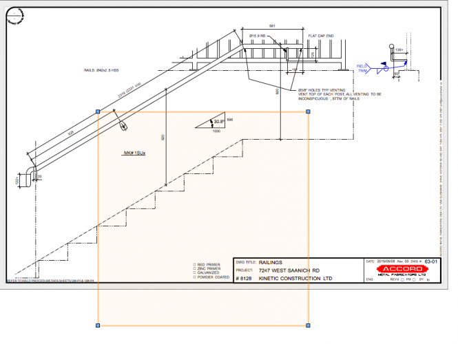
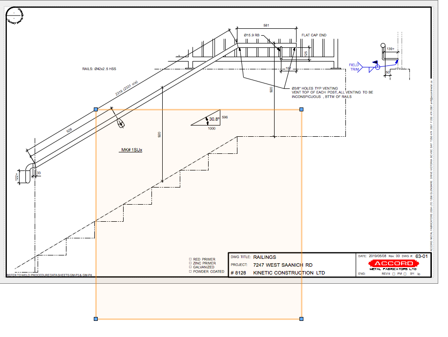
What happens is that the visual boundary definition of page based symbols are incorrect after having entered and exited annotation editing of a standard viewport.
Screen capture attached of condition after exiting edit mode. It may also be related to snapping while in group/container mode because dotted/dashed outlines of items in our titleblock appear as the mouse moves through the annotation editing environment allowing one to snap to points of the page based symbol. Not where it is but where it would be if the symbol had been scaled up using the view port's scale factor. Below shows the boundary of that slope symbol. Its 10x larger than it should be which is the view port scale.
-
I think I have figured out how to repeat the situation. I have a simple polygon without any arcs, had six sides, appearing like a stair stringer made from a C channel. it was drawn up in layer space on an incline with a symbol representing bolted on stair treads duplicated up the incline. When viewed through the view port only pairs of black solid fill circles are shown representing the holes that need to be drilled through the stringer. Now this was all grouped and assigned a class that could be visible or not. Separates the stringer from the guardrail that I also usually draw at this time but probably not required to show the problem. Now on a sheet create a basic view port and turn on the applicable layer. Note that I normally have a layer override so the class colours all become black or grey for printing. Rotate the view port so the stringer becomes horizontal, usually some where between 28 and 32 degrees. Crop the view port. Scale is around 1:10 to 1:16 but not part of the problem as far as I can tell. Now this is what I am thinking is triggering the inability to snap; flip the view port horizontal. I often do this to show the opposite stringer without having to draw another. Now try to sequentially dimension across the top side of the stringer. You will probably be able to snap to circle centres but not all of the polyline vertexes nor the circle quadrants. The latter for obvious reasons, the rotataion of the view rotates those as well. But the flipping of the view port causes the vertex snap point to be somewhere else other than the anticipated visual location.
Writing this at home so I don't have access to a file.
I am also wondering if there is a connection to the ghost of our titleblock symbol that I posted an image of in a previous posting. That is a plugin of a page based symbol (the green ones) that is being resized based upon the scale of whichever view port one happens to be adding annotation to rather than the 1:1 scale of the sheet where they typically reside. It regains its proper size through any form of editing or generally movement. The lines and text, etc still display correctly throughout, only the perceived size changes, that tint that appears when selection is made.
-
Arrgh, happened again this morning. Viewport was not rotated this time; and it was snapping to centre points but not some of the end points of simple lines. Saving the file didn't change the behaviour but restarting VW did. I just updated the drivers to my Razer mouse, its been a couple of years. Maybe that will fix the issue.
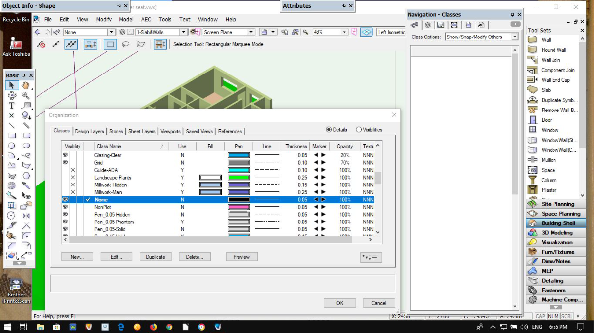
Are there Run-time libraries req'd for Navigation palette?
in Troubleshooting
Posted
And another but the layers tab, only showing a column of storys