LarryO
-
Posts
428 -
Joined
-
Last visited
Content Type
Profiles
Forums
Events
Articles
Marionette
Store
Everything posted by LarryO
-
@Tom Klaber Be sure to go and vote up the wish list item if this affects you.
-
Copy-paste grouped Viewports across files to be restored now.
LarryO replied to _c_'s question in Wishlist - Feature and Content Requests
This is only a perception by those who don't experience the time and frustration that this workflow saves those of us who use it almost weekly. This paternalistic barrier to a necessary workflow procedure needs to be reversed soon! Those of us who have been required to utilize this technique are aware of the potential pitfalls and aspects that must be reset for it to be successful. When the engineers incorporate this ability into the copy/paste functionality it will be welcomed but until then we are accepting the responsibility for using the original technique and the barrier to it needs to be disabled. Still using our VW2019 licenses instead of our VW2021 in part because of this. Yours truly, Larry -
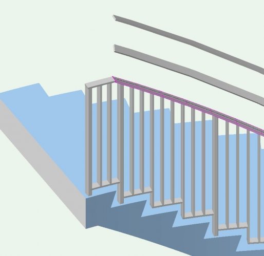
@Matt Overton Yes, SWEEP was the solution. The tool keeps the profile plumb to the work plane rather than perpendicular to the incline of the path. So I needed the slope to determined the distortion required for the vertical face of the profile so that the thickness of the steel bar capping the guard railing remained at 15.9mm.
-
@markdd Thanks for the thoughts, The stair profile was thankfully the easy part. My focus in this instance is on manufacturing the custom railing; metal fabrication shop drawings.
-
As mentioned I couldn't utilize the helix line as a path for my rectangular profile due to some rotational issue that I don't quite comprehend. You can see two of my efforts in the picture. The top most was the closest to being correct where I had rotated the rectangle 45° in an attempt to plumb the profile's sides. The middle profile is what the tool produced without corrections. I reminds me of the angle a person might be traveling at while riding a water slide due to centrifugal force. I eventually used the standard sweep tool. I calculated manually what the height of the profile would be when sliced at the angle of the stair's incline along the radial centre line of the railing's location. (geometry courses have a purpose) The result is the pink profile embedded over the profile that the stair tool created. You can also see the helical line I forgot to delete that I was attempting to use as a path along the top centre of the railing. FYI the 10.93° was the angle from post to post, equivalent to three tread nosings. Hence the rise of 473.3 was also across those three risers. 4153 is the radial centre line of the railing.
-
Well in the end I used the stair tool to create the top rail and just threw away all the posts and pickets it creates. The helix tool rotated the rectangular profile such that I could not see how one was to align the start to the end of an adjacent identical segment. 😞
-
I found a video. Thanks all. Having to use a line to determine the centre axis and with its length defining what I thought would be called the pitch is what I was missing. For some reason VW uses the term pitch to identify the sweep of the arc. I find that puzzling. If I used VW's arrangement of terminology to get some steel rolled it most certainly would not come back as expected. hehehe
-
I've attempted to use it but I'm not sure what object it is expecting one to have preselected and there doesn't appear to be a means to enter the sweep of the arc only a start location.
-
Is anyone familiar with how one goes about creating a helix path line? (corkscrew) I have a radius of 4153mm sweeping 10.93° and rising/dropping 473.7mm. Ultimately I want to have a rectangular profile follow the path so I can clip off a series of pickets and posts or merge it with those same pickets and posts. FYI: initially I tried to use the staircase tool to do this for me but I couldn't get the posts to land in the same location on their respective treads with that tool. I also am required to step the bottom rail, which I achieved easily enough.
-
In VW2013 sp4 the functionality was still called Batch Print.
-
Is anyone aware of what settings control the quality of the bitmap created when decomposing a pdf? I find that the image quality of the bitmap produced lacks the crisp focus of the original pdf. The document preferences for Resolution are at their max, including output at 600dpi but I don't feel that these are necessarily related to this process. Is it possible that this degradation of the bitmap image quality is a result of pdf licensing requirements?
-
Structural Shapes...Can You Add Additional Sizes
LarryO replied to ericjhberg's topic in General Discussion
I believe the answer is yes. for imperial find the data file Angle-Inch.txt open with a basic text editor (not MS_Word the file must remain a txt file without hidden formatting characters) add the specifics of the shape following the order presented in the file. (Make sure you save a copy of the original file elsewhere in case you accidentally delete something) I've forgotten if the entries are delimited with a space or a tab between each. A normal carriage return is used for terminating each line. open the plugin editor and select the angle tool. While you cannot see or edit the script you can view and add to the parameters' data. So go to the parameters and find the list that is used for selecting the size and enter the size of the angle in the same format as presented, spaces are as critical as the other characters. There maybe more than one parameter data set to edit in some of these structural tools. I've forgotten if they are utilizing the parameter strings or not. Of course this will have to be redone with every major upgrade as the tools are not checked if they have been customized. -
You'll need 5 or 6 levels. Draw a sample in Vectorworks from which you can take measures is the simplest approach. If you make each level a different colour it is easier to visualize while creating a hatch. These numbers will give you a chevron pattern but maybe not to the spacing you desire. LVL 1 / 0,0° / 50.8,45° / 0.5 / 50.8,-45° LVL 2 / 0,0° / 50.8,-45° / 0.5 / 50.8,45° LVL 3 / 35.9,0° / 50.8,45° / 0.5 / 50.8,-45° LVL 4 / 35.9,0° / 50.8,-45° / 0.5 / 50.8,45° LVL 5 / 0,0° / 50.8,0° / 1.0 / 50.8,-45° LVL 6 / 25.4,45° / 50.8,0° / 1.0 / 50.8,-45°
-
Dimension class and None class are default classes that must exist in every file; therefore they cannot be deleted from a drawing file. While you can rename the Dimension class it still retains an identifier that prevents it from being deleted.
-
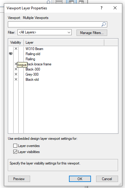
What I came across was that all the tabs were already separate menus, "detached" and it is not apparent how to return them to the 2019 style tabbed arrangement that is familiar. This being compounded by them all being blank with the title of Vectortworks across the top. The latter I found that by opening them one by one from the window palette menu I could refresh each menu to identify which one is which.
-
I've noticed that the data now has its own palette from the object information but they both are opening and closing using crtl I. Similarly the navigation palettes are all opening and closing with the same keyboard shortcut. Is there a new setting somewhere to enable the former tab functionality or a means to stop palettes that do not have a shortcut specifically assigned to them from opening. Do I possibly have to rebuild my workspace menu instead of using the migrated one?
-
Why are there stray lines when printing 3d objects?
LarryO replied to LarryO's question in Troubleshooting
Are you postscript printing? or in a mixed environment and using PCL to your Cannon? We have been the latter for some time. -
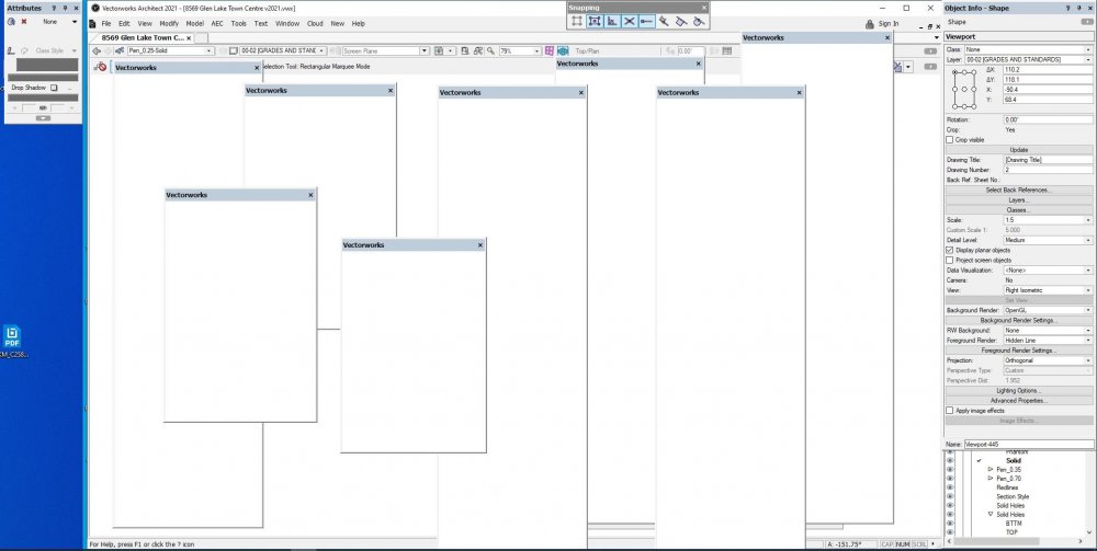
fresh install of 2021. migrated company menu from VW2019 via install. Switched to company menu and closed most of the now non-tabbed Navigation and Object Info windows. Switched to Architect and back to company menu. Look at what I found hiding near the right edge of the monitor. If I open, lets say the data palette, and close it then one of them will become the data palette and it will close when triggered to do so.
-
Why are there stray lines when printing 3d objects?
LarryO replied to LarryO's question in Troubleshooting
no difference in the output. Not a small file but here it is, plus the sysinfo of my workstation. Prefer that files are removed after your have them. One never knows these days what those dark webbers' find in this info to scam us with. 8569 Glen Lake Town Centre v2021.vwx -
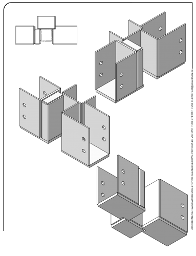
This is what I see on the monitor in VW2021 using OpenGL. In the pdf are scans of the pages that VWs prints. What is causing those stray lines to appear? This is something that has been frustrating when attempting to use the 3d aspects of Vectorworks since VW2012. Both Minolta and Sharp printer/copiers communicating via PCL. Our MinoltaC368 series printer copier is only three years old and has been upgraded with 2019 firmware/software. This has been happening from both Win and Mac platforms. It will also occur when printing pdfs generated from VWs. Bluebeam will display the pages as expected but the output to a printer is corrupted with stray lines. Any thoughts on how this can be resolved? If we have to resort to 2d only drawing techniques the industry may as well revert back to MiniCad 7. Think of all the inexpensive hardware we could save from the landfill! Secondary problem, I have noticed that the different shades of grey applied to these objects (solid fill attribute colour) are not being acknowledged in VW2021. SKM_C25820092414200.pdf
-
If you still have the previous version installed you can copy that version's stair tool over to the new version's function library. It may or may not function due to changes in the underlying commands but it is worth a try. You would have to add it to your menu for new use but that's not necessary if you only want the existing instances to function.
-
It is fun to experience the success of drawing something via a script (I've gotten caught up in that aspect many a time). From a practical point your symbol library already exists and it is a great launching point for your plugin. I assume that you already have these 300 plus profiles drawn as a polyline, each in their own symbol, and pre-indexed by name from those catalogues in a Vectorwork's file. This makes an excellent a library resource file that your plugin can search through based upon an index name typed into the OIP, or emulate the technique used in the wide flange steel beam tool (long lists of predetermined sizes sorted by applicable standards organization, add an option to branch to a script for non-standard entries). It is also easy to add non-standard variations to the library file by simply duplicating a similar existing symbol making the edit and giving it a unique name to add to your list. The bulk of your profiles remain in the library file stored on your drive while the plugin only imports the profiles that are utilized into your project file. At this point if these symbols cluttering your resource palette you can convert the imported instance to a group and ungroup leaving only the outline that was originally in the symbol. follow it by deleting the named symbol from the symbol library. Alternatively your script can create a folder (if it doesn't already exist) to contain these symbol definitions then repeated use of a particular profile will not significantly add to the project's file size. Ok, I had nothing better to do tonight to distract myself from thinking about dental surgery tomorrow.
-
Personally, I leave the setting off because unless you are only using basic entities throughout they fail to associate. This I find to be true for 3d objects, entities which have been grouped, PIO objects, solids that have been edited (add, subtract, section, etc.)
-
Just guessing here, It might be one of the tools that require calling via the custom tool call function in the same manner that one would call a PIO.