Dubman
-
Posts
363 -
Joined
-
Last visited
Content Type
Profiles
Forums
Events
Articles
Marionette
Store
Everything posted by Dubman
-
Thanks!
-
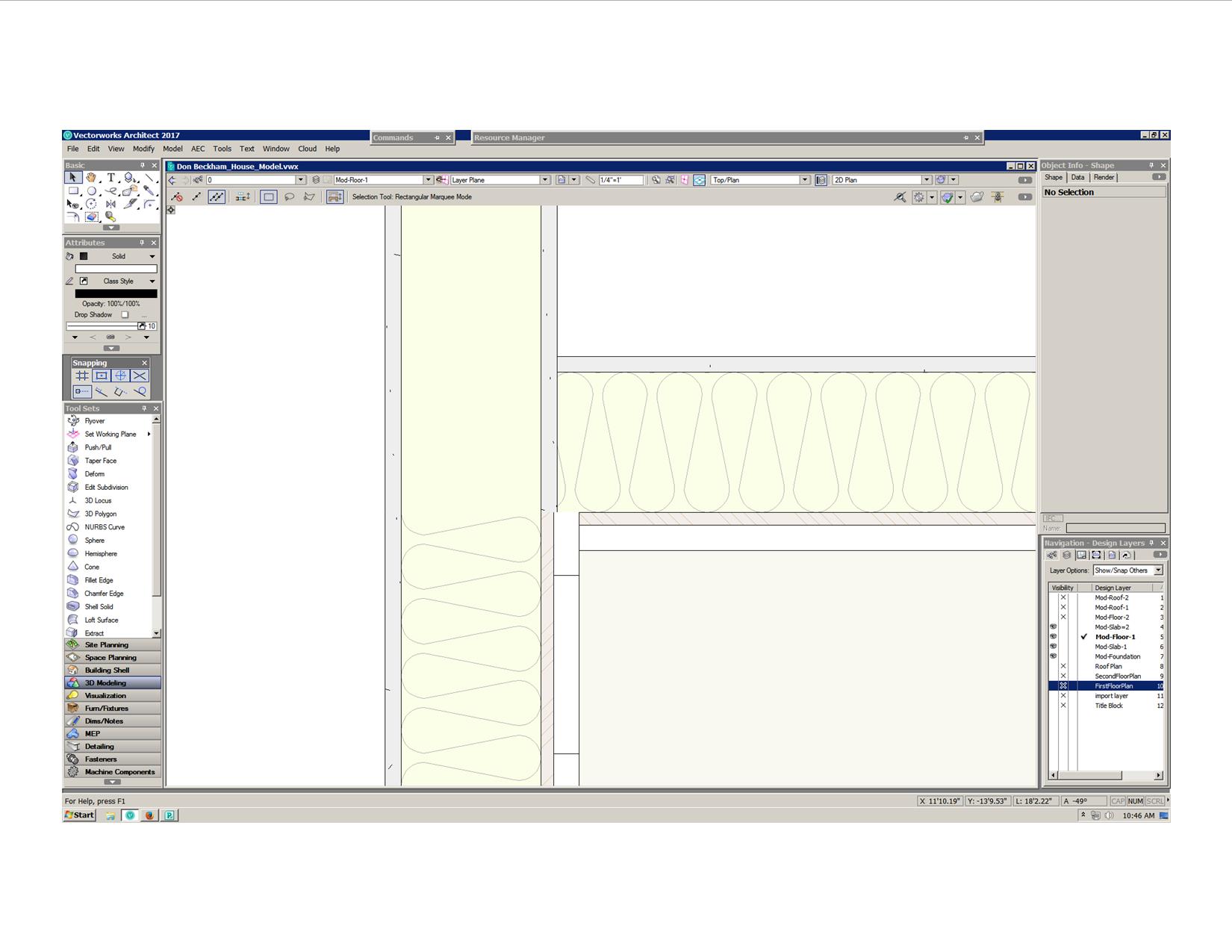
I've exported a house model as a sample for a new client to see what I am able to do with models now. But a porch ceiling ( a rectangle with solid fill with class & layer turned on ) and a large ground level rectangle with light green solid fill with its class & layer turned on, do not show up in the uploaded model. When exporting the upload file I have selected the ( All Visible Objects In All Layers ) & Medium quality. Any reason these two objects are not visible? Thanks!
-
I can turn off the saved sheets but not the saved views, I use saved sheets as my final drawings for printing & saved views to find the drawing in the design layers & never print them, it would be nice to turn off the saved views so it would be easier to print the saved sheets that I want to print at that time. Thanks
-
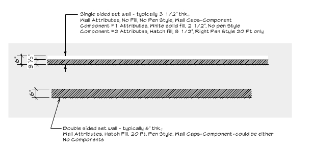
Oops, the top/wall styles did not export correctly, this is the correct one, I was showing them all with light grey background to show the white fills.
-
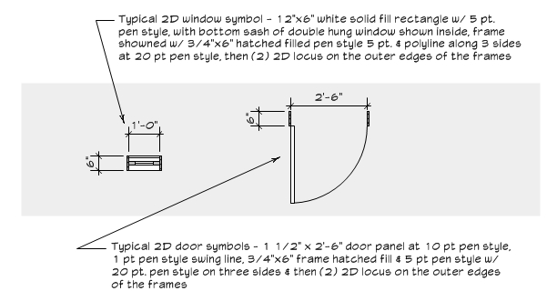
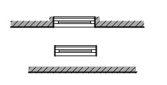
OK, I think I finally got this figured out with the help of everybody. With using suggestions from each suggestion I am able to do what I have been trying for some time, that is to enter the same 2D door & window symbols into a single sided & double sided typical set walls. The main problem I kept having & now understand why it was not happening is to have symbol insertion wall caps with having only a solid pen style on one side of a wall, even with wall caps set to components. The only way to get a wall cap on a symbol insertion is the have the wall's attribute set to a solid pen style or the components pen style to be solid on left & right sides, with out these you get no wall caps. So now I know that the wall cap must be added to the symbols, as some suggested. Since the actual set doors & windows are in a 3/4" x 6" frame, I've drawn them to that size. It took me a while to figure out how to get each symbol to work with both wall thicknesses & allowing me to flip the symbol to either side of the wall correctly. I do not think I could have figured it out with out each of you suggestions! Thanks to all of you! I always tell all non VW users how great this forum is!


-
Model Roof Face VS. Create Roof with surface hatches
Dubman replied to Dubman's topic in Architecture
yes I have the latest version and service pack Thanks for doing this, I now feel better knowing that what I have been trying is achievable ! -
Model Roof Face VS. Create Roof with surface hatches
Dubman replied to Dubman's topic in Architecture
Hay Alan, could you please show me that same if roof if you still have it in hidden line rendering mode. Thanks! -
Yes! Thanks Jim, I was just trying another route myself, I knew there had to be an easier way with just a symbol insertion & be done with it & then being able to move it easly. Thanks again!
-
I think that is the best suggestion yet & just have the window symbol not inserting into the walls. I thought of a way last night while trying to sleep, was to have the 6" deep jamb lines part of the window symbol with no fill out past the wall fill which is more correct, the doors & windows in a single sided set wall just have a 3/4" jamb frame that sticks out the back of the set wall with no other thickness, I've always drawn them this way for better visualization. Thanks again, I really appreciate the suggestions !
-
Model Roof Face VS. Create Roof with surface hatches
Dubman replied to Dubman's topic in Architecture
Thanks Allen, that is the way I will do it & just add the soffits, which may be better so that I can make the fascia board correct with it extending down below the horizontal soffit level & have a correct frieze board all in one extrude. Thanks again! -
yes, the third is my set wall style with no symbol inserted
-
Model Roof Face VS. Create Roof with surface hatches
Dubman replied to Dubman's topic in Architecture
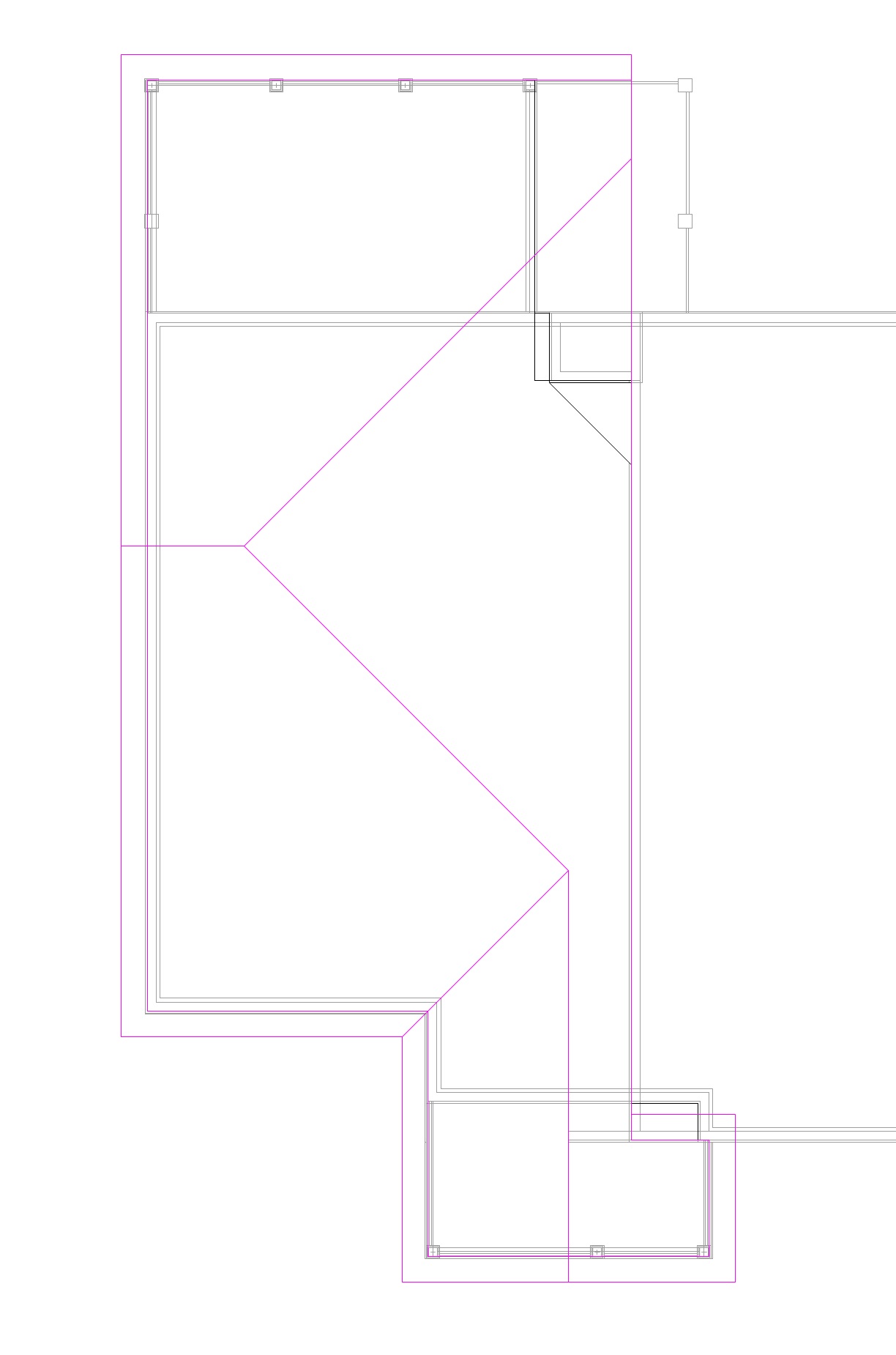
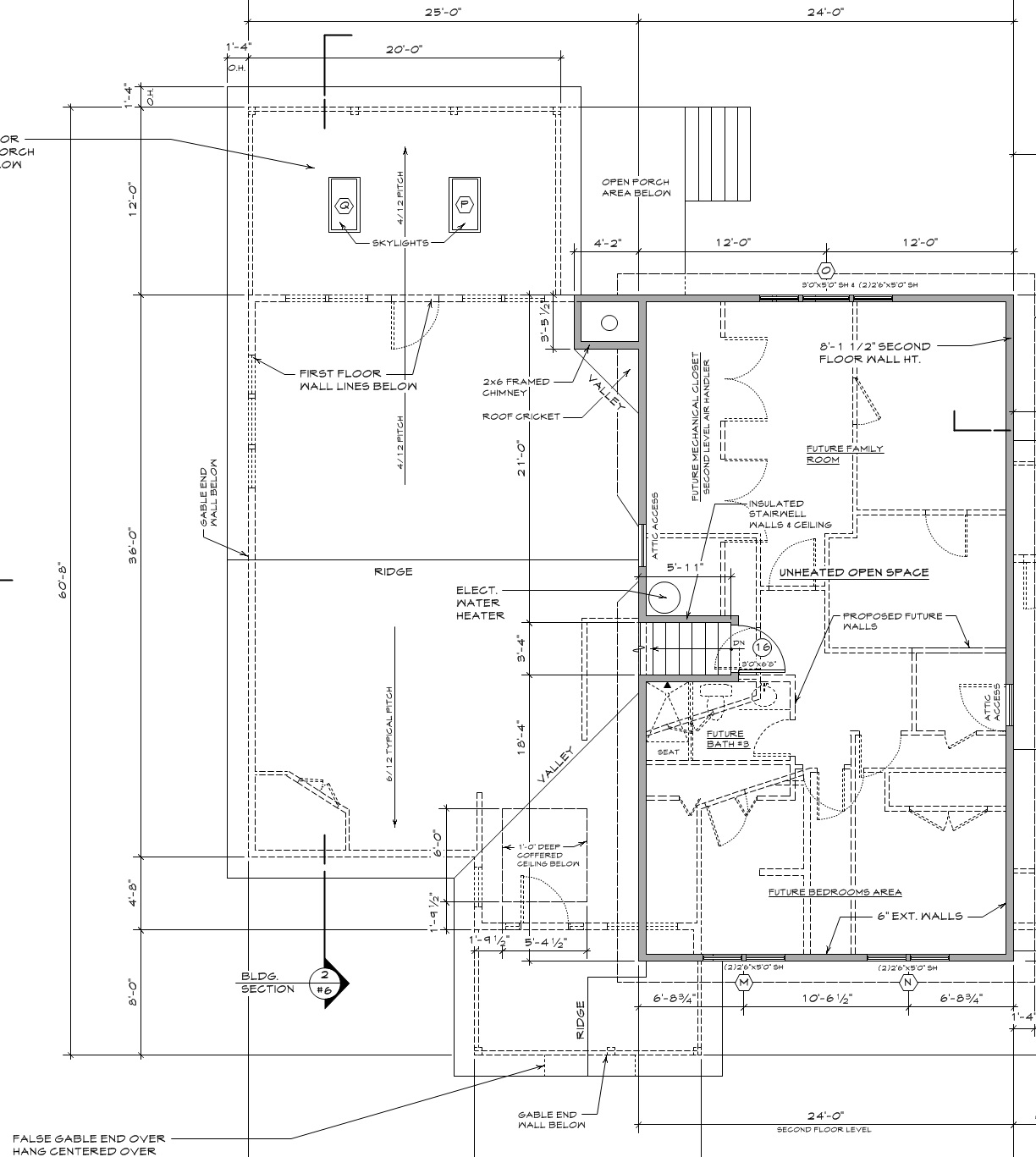
Every time I try to make the first level roof on this side of house with the extension out over the porch it cancels out the slopes & goes back to the polygon & says can not create the roof. I also can not get the over hang on the gable end that is set back, the over hang goes towards the rear, opposite of what your showing. See my try with roof lines in pink color, the right side of what should be the ridge is selected as a gable but does not show correct at all, also you can see where the set back porch gable over hang go back into the second floor, not out over the porch front gable end, I even tried a negative over hang value but no luck. Also attached is the actual second floor plan showing the entire first floor roof I;m having problems in using Create Roof. How did you get your set back gable end over hang over the front gable roof? Thanks for your suggestions!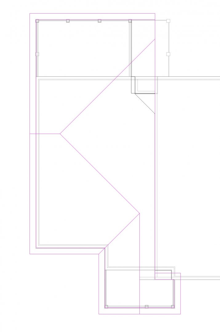

-
I've been trying to create a custom wall for my set design work on TV & film productions. We build one sided studio flats that I show 3 1/2" wide, brick hatch fill & 20 pt line weight on one side representing the finished wall side. Then to be able to insert my 2d door & window symbols & have the 20 pt line wall breaks on each side. This I have not been able to achieve. Also I've been trying to get the symbol to show a 6" deep jamb which I do by placing a 20 pt line 6" long on each side of the symbol (see ref. window symbol by its self) but can not figure out how to get the additional hatching indicating the jambs 6" depth finish surface. So I have been drawing plans the way of the first/top image, a 20pt line & then adding a 3.5" fill with hatching & no line weights. This adds time to achieve what seems like I should be able to do with a custom wall' I have seen the set wall flats in the resource mgr. but I have never drawn a set wall in plan view like those so I would never use them. Thanks for any suggestions!
-
Model Roof Face VS. Create Roof with surface hatches
Dubman replied to Dubman's topic in Architecture
Yes I agree on the soffit flexibility. This is what I was going to try. The only thing in Hidden Line Rendering it shows the line between the objects. That is the only thing SketchUp has the Vectorworks does not, the ability to hide a edge line of an object. Thanks !!!! -
Model Roof Face VS. Create Roof with surface hatches
Dubman replied to Dubman's topic in Architecture
but how do you add horizontal soffits to Roof Faces? -
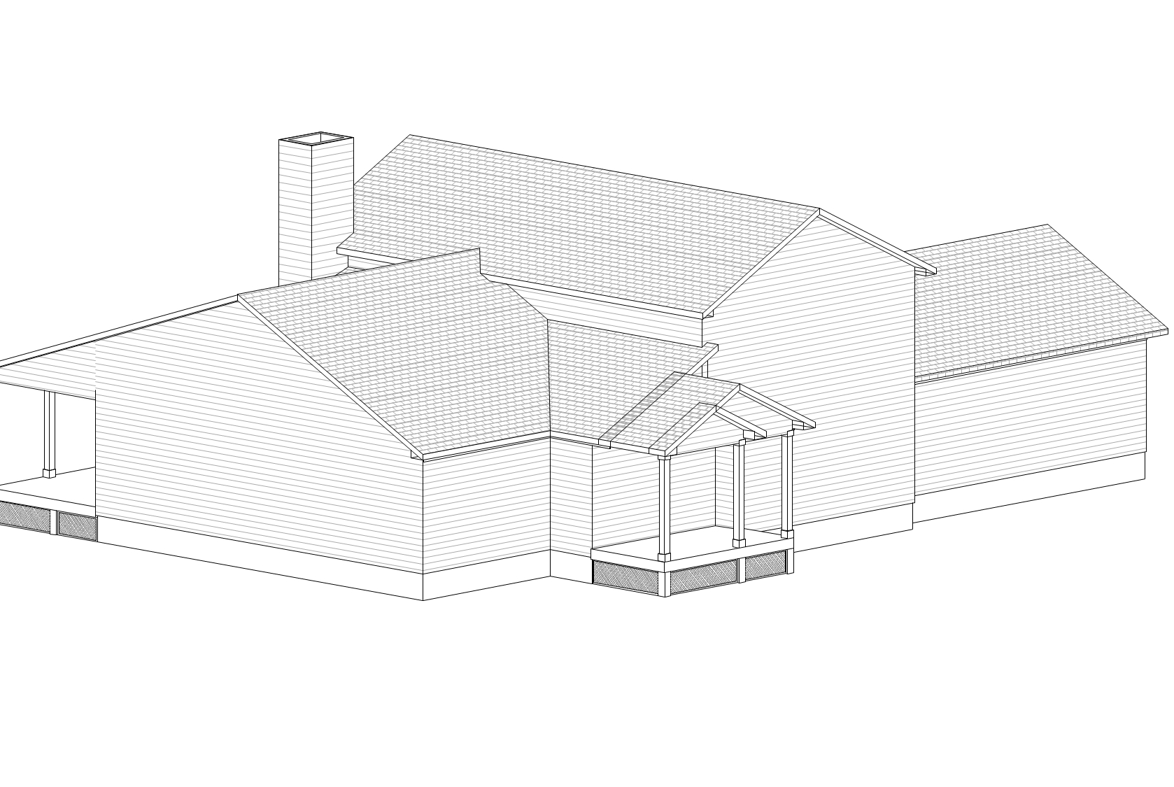
I'm trying to make a model that sows no colors with surface hatches to represent materials. I think using Hidden Line render mode is the best way, but my Create Roof soffits have no fill & you see right thru them. Not able to resolve this. If I use Roof Face it gives no option for soffits & have not tried to add them myself yet. Also with this roof extending out over the porch with a gable end with another false gable end over hang centered over the steps I could not make this with the Create Roof with out making separate roofs with the same surface with no way to join them. This is no problem in OpenGL, you do not see the over lapping lines or where on roof abuts another. But this is obvious in Hidden Line render mode. Is there any way to join these roofs with same slope as one? With using a roof shingle Surface Hatch-RT I can not change the color to a grey scale or white. So I am using a white roof shingle & a white lap siding & viewing it in OpenGL, but everything looks grey. In White Model or Realistic Colors White render mode I get no surface hatch. I'm still trying various things, any suggestions ? Thanks


-
Snapping Pallet tools working intermittent & other
Dubman replied to Dubman's question in Troubleshooting
After resetting the VW preferences, it tool a little while, but back to same thing except for the press shift to constrain the direction when moving something with the cursor, this seems to be working better. The smart cursor cues & the inch & foot tick marks only are visible after pressing the key twice & then I see two of them & backspace delete to have just one. I'm going to buy a new key board, both that I have tried have many hours on them & I'll then report back. -
Snapping Pallet tools working intermittent & other
Dubman replied to Dubman's question in Troubleshooting
With the different keyboard the foot & inch tick marks stopped working again when typing a note 4" step down, I have to press the key twice to it the tick mark, but then get two of them & have to back space delete one to get a single inch mark. It is always something with computers! -
Snapping Pallet tools working intermittent & other
Dubman replied to Dubman's question in Troubleshooting
Thanks Zoomer, I'll give another keyboard a try & report back about it. But I do not think the key board is causing the snapping, especially the smart cursor cues to stop along with the constraint of a horizontal direction. -
On occasion the vertical/horizontal constraint stops working. As I click to start drawing a line for instance, and press the shift key to constrain the line horizontally to the right, its starts out correctly & then starts going every direction with no control in any direction. I have also noticed that this coincides with the smart cursor cues stop working. When opening the smart cursor settings I see the show cues is de-selected, in which I always have selected. I even deleted in the Workspace Editor Keys-Other Keys to toggle smart cursor cues so I would not accidentally turn it off. Also, on occasion, I can not enter the (") inch tick mark when typing text. If I press twice then I see two of them & have to Backspace one. I'm able to do it in other software with no problems. It works better after a computer reboot. The lost of constraint control happens also when moving any object or objects. I can not tell if these are a setting I do not have correct, my computer problem or software problem. Thanks for any advice !
-
Thank you Wes!
-
OK, I've gotten everything to work with different wall joining & component joining. They only thing I have not been able to figure out is the alignment of the siding. Thanks!
-
Yes it is except for the siding on Wall #1 ends at this corner & is an interior past this intersection. How did you get the siding to align? Also, is the siding & sheathing on Wall #2 abutting the Wall #1? Thanks!
-
I'm using the wall style Ext-2x6-Wood-Siding wall. Wall #1 is a 9'-1 1/2" ht. wall. Adjoining Wall #2, top of wall is same elevation, 9'-1 1/2" ht. and the bottom is lowered 4" and the sheathing & siding is lowered more to align with a lower stud wall to the right. Problem I'm having is to align the siding between these two walls. The only way I can get Wall #2 lowered siding & sheathing to abut the foundation of Wall #1 is not to join these two walls as you can see in the attached plan image, I had to use an interior 6" wall, Wall #3 between these two walls. If I join Walls #1 & #2, the extended sheathing & siding of wall #2 has a diagonal cut from the diagonal joining of these walls, which is not correct visually & can not figure out how to correct these two components in Wall #2. If I join Walls #1 & #2 how so I make the sheathing & siding of wall #2 abut the wall stud line of Wall #1? I know it is a small detail, but it is not visually correct in the model & seems like there should be a way to do it that I can not see. Thanks for any suggestions!


-
When Updating my hardware & software setup in signature, where do I do this? Why is this not update-able under my profile?