Thomas Peters
-
Posts
60 -
Joined
-
Last visited
Content Type
Profiles
Forums
Events
Articles
Marionette
Store
Everything posted by Thomas Peters
-
Yes, if by intelligent symbol you mean a red symbol? As someone with some experience in defining bugs, I don't like using the phrase 'it does not work' in this context, but I do hope I have been clear with my description of the issue? If I have been vague or unclear anywhere, please let me know. If I create a new red symbol in your document and import that into a new imperial file, it does work. If I create a new red symbol in your document and import that into a new metric file, it does not work. (Does the German language version even have an imperial option?) If I paste the marionette into a new metric file and then create the red symbol in the new document, it does work. Posts like these have helped me learn just about every tool I know, so I hope this isn't drawn out, and I hope that future readers will benefit from this.
-
Thank you- Yes, I can reproduce that. I don' throw this term around lightly, but I do think then there's definitely a reproducible bug here? Specifically, a but that affects documents started with metric units. Do you agree?
-
Thank you @m.graf, the only difference I can see is that you've drawn a wire from the resultant object to the dummy node at the end? This does" tie the room together" nicely, but if I import the red symbol from the Resource Browser in your file into a new Blank (metric) document, it still doesn't appear when insert it. See attached screen recording. If it's in a document and it works then it works perfectly, it's getting it into the document that's giving me trouble. Thank you also for your other contributions to this forum, I'm currently using parts of your Object Builder network to read worksheet data for my next Marionette project. mystery symbol.mov
-
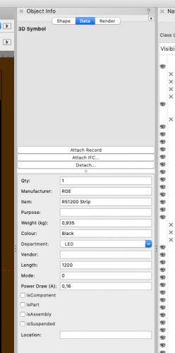
In the interest of accommodating all unit preferences, I've made sure to use dim nodes for all dimension values. So far this works perfectly if I change unit preferences inside of my working document. If I create a new imperial document, I can import and operate these object nodes perfectly. If I create a new metric document, they do not even appear on the design layer, and the Shape pane in the OIP shows me nothing aside from that there should be 'something' there... I'm inserting some hybrid symbols and manipulating their z height. There isn't very much to the network at all. Is anyone able to reproduce this? Any advice would be appreciated. Stand Hollywood Combo Triple.vwx
-
Is it possible...(worksheets question)
Thomas Peters replied to Chris Burton's topic in General Discussion
Perhaps this will be useful? Keep us updated on your progress please! -
Is it possible...(worksheets question)
Thomas Peters replied to Chris Burton's topic in General Discussion
It may be helpful if you tell us what you're trying to achieve with a 2-way link. I've got a wishlist item open to be able to bulk edit record fields easily, and I suppose a live-link with excel is sort of in the same train of thought: a mass editing of cells. -
It sounds to me like you are reinventing the wheel here- check out the ConnectCAD package, it can do exactly this and will most likely have other functionalities that will be able to improve your workflow.
-
Is it possible...(worksheets question)
Thomas Peters replied to Chris Burton's topic in General Discussion
Excel files are 'static', as are VW Worksheets. A 'live' link would be a database, in which case, you'll want to look into Database connections: https://app-help.vectorworks.net/2021/eng/index.htm#t=VW2021_Guide%2FDatabase%2FDatabase_connectivity.htm&rhsearch=Database&rhhlterm=Database&rhsyns= If you figure it out, please make a tutorial for the rest of us, because we want this sort of functionality too. -
There's no problem, this is fundamental to how Vectorworks... "works". The file you are importing is made in some other CAD software, which works with Polygons. Vectorworks works with Vectors, and ultimately this is how Vectorworks interprets that polygonal data to be able to represent it. Using the imported data is a) messy, and b) guaranteed to slow your project down to an unacceptable crawl. This is not an unusual situation to be in, and what I do in this case is work in a new 'transitional' file, and re-draw the object I want over top of the imported mess as though I were tracing it. As for obtaining VW models of appliances, furniture, etc, there is a vast internal stock library of these. It is obviously not exhaustive or by any means complete, but it is substantial. Might be time to upgrade?
-
I want to return to this thread with some updated feedback on the way this works in VW2021: being able to select a symbol from the OIP is wonderful, except that I now have to chose either the 2D or 3D part of the symbol, not the hybrid, and on some projects I do actually need both. In summary: I would like to have my cake and eat it too. Please and thank you @Conrad Preen
-
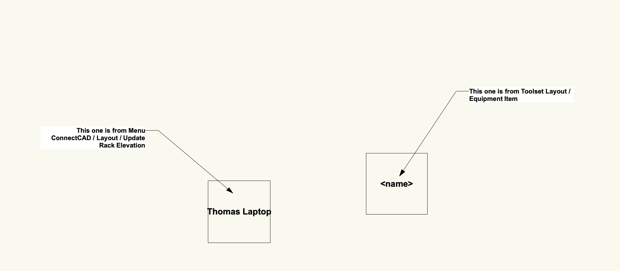
@Conrad Preen, In order to fit into the CAD Standards of a project I am working on, I need to name my design layers following a specific convention. It would be great if I could specify a different layer for the "Update Rack Elevation" command to populate, maybe in the ConnectCAD Settings Dialog? Thanks!
- 1 reply
-
- 1
-

-
Batch Editor for Record Fields
Thomas Peters replied to Thomas Peters's question in Wishlist - Feature and Content Requests
Thank you @markdd, that's the procedure for a single object, but I am looking to efficiently manage many objects without having to edit each symbol individually. A lot like @JBenghiat's Lighting Symbol Maintenance dialog that came with Savvy Symbol Key forever ago, except I want to edit a record that isn't the Light Info Record. Use cases for example are adding new stock codes for a new vendor, modifying naming conventions, updating values, attaching a new field to a format that needs individual data for every object that carries it... I can go on. I'm open to other workflows as well? -
Thank you, I appreciate your time in responding! See wishlist post:
-
Batch Editor for Record Fields
Thomas Peters posted a question in Wishlist - Feature and Content Requests
It would be really useful if there were a dialog where one could edit the contents of fields in a record in all objects that have it attached in the resource browser: much like the newish batch rename dialog. To be clear, I'm asking to edit the data in records of objects in the resource browser, not those that are already inserted the document, which I would do in a worksheet if need be. I'm looking to work more efficiently on my resources, before they go into a document. A step in the right direction would be even the ability to edit those fields directly in the bottom-right window of the Resource browser where they are currently only displayed. See also: -
Thanks @Pat Stanford, that works for symbols on design layers, but not those in the resource browser. Everything I know about records I've probably learnt from your posts, I'm thrilled that you've responded to mine!
-
Under Tools/Records I can bulk-apply a record to the contents of a symbol folder within the resource browser, and make one-shot changes to the fields in that record for the contents of that folder. What would be really useful is if there were a dialog where I could edit the contents of all fields in that record in all symbols that have it attached: much like the newish batch rename dialog. Perhaps even symbols that have nested (nested-nested-nested) symbols with the record attached. Does something like this exist, that I've missed over the years, or is this a feature request?
-
Thank you @Conrad Preen, that is an efficient workaround, and not at all backwards like I was imagining. I've tested it and my current solution is to let the Video Screen tool insert the lens symbol, and then ConnectCAD insert the projector body symbol- thus, one hand washes the other. For 20 seconds or longer. I should have been clearer. It's not that I'm imagining a ghost hand doing my work for me- instead, I'm trying to adapt my existing library of assets and workflow to the new dimensions this toolset offers, and I thank you for being so present and responsive on this forum.
-
@Conrad Preen, here is another scenario: integrating with other PIOs. Projectors need power, a video signal and ethernet, and I'd like to put projectors on my schematic. The catch: they need to be inserted by the Video Screen tool to be useful in 3D space, so I can't use the above 3D Geometry trick without ending up with double objects, which is what I'm trying to avoid in the first place. Is there a clever way to make this work? It's basically the reverse: I am inserting the Projector and imagining that 'update rack elevation' would work backwards to give me the schematic as the outcome.
-
What is the best workflow for customized device appearance?
Thomas Peters replied to Thomas Peters's topic in ConnectCAD
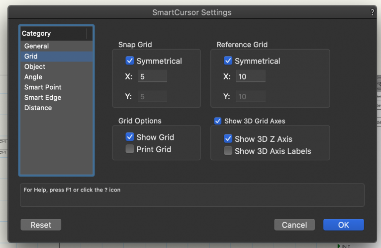
Thank you! It's all in the smart grid settings. I've set it to 5mm to give me 40mm which looks like it fits most of my IOs so far, and adjusted my header symbol to match- so far so good!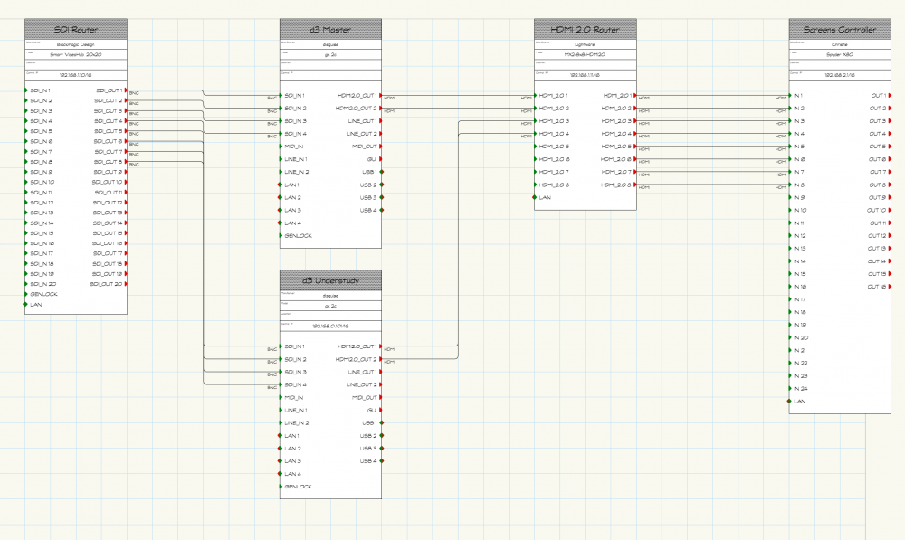
-
To preface, I'm working in a new document created using the ConnectCAD.sta template file, the file is the attached ConnectCAD_14May2020.vwx I would like to schematic devices to conform to a standard appearance, but when I start modifying the components of the System Symbols folder I introduce problems. A customized dev_label_xxx symbol works great, and to change the font of the sockets and customized skt_text_L and _R look good, until it doesn't- new devices come in at very odd dimensions, so I must be modifying something else when doing that. Further, is there a way to determine and constrain the width of a device so my dev_label_xxx can fit? ConnectCAD_14May2020.vwx
-
Amazing, thank you. This is going to improve my workflow significantly going forward. Not only does that work perfectly and immediately, but it also accepts spaces and other characters as well. The downside is that I lose the device symbol I've created because I'm essentially overwriting it, so my next test is going to be figuring out how to add/update devices in the internal library.
-
Thank you very much @Conrad P, unfortunately I can't seem to replicate that result..? Attached are three .vwx files: - empty doc with only one object.vwx, which is the ConnectCAD device - empty doc with only one symbol.vwx, which is a regular symbol, 3D only - after merge.vwx, which shows the result of doing both Update Rack Elevation, or Inserting a new Equipment Item. I'm probably just missing a step somewhere? Thanks Thomas empty doc with only one symbol.vwxempty doc with only one object.vwxafter merge.vwx

-
Is there a way to pull 'other' geometry in? For example, I want to have a Lighting Console present in my Signal Flow Chart, and I also have to account for it in 3D space, and I do not want to have to add it twice into two places manually. Everything in the rack is great, but in live events there is a lot of important gear that doesn't go into racks. I'm happy to expand on what I'm trying to achieve and give some examples if needed?
-
@michaelk thank you for making this. This is super cool! Any chance of some class manageability making it into v1.0? I.e. the ability to rename the created classes and having the stay that way?
-
VW2018 SP5 can't see record formats in OIP
Thomas Peters replied to Thomas Peters's question in Troubleshooting
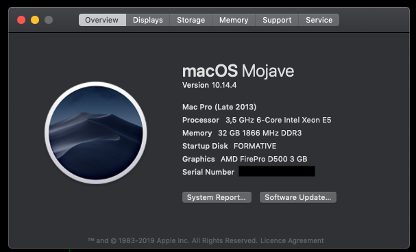
I still have the exact same issue in VW2018, now on SP6, and on a completely different machine. All known updates installed. Downgrading this machine to High Sierra seems ridiculous at this point, but I don't have this issue on my MBP that I downgraded after the initial post here. I've paid good money for this software, I expect it to function properly, on the current operating system, for at least a few years.