Bas Vellekoop
-
Posts
651 -
Joined
-
Last visited
Content Type
Profiles
Forums
Events
Articles
Marionette
Store
Everything posted by Bas Vellekoop
-
@Markvl Dankjewel! 😉 @cberg Attached a zip-file with al the settings. Because image effects are not recourses (as far is I know) I attached a 'print screen' in the file. lighting setup 2019.zip
- 31 replies
-
- 1
-

-
- renderworks
- rendering
- (and 1 more)
-
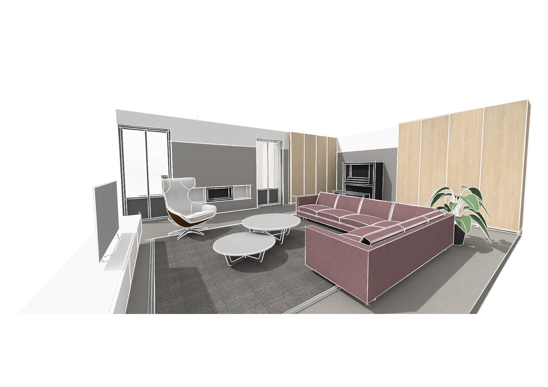
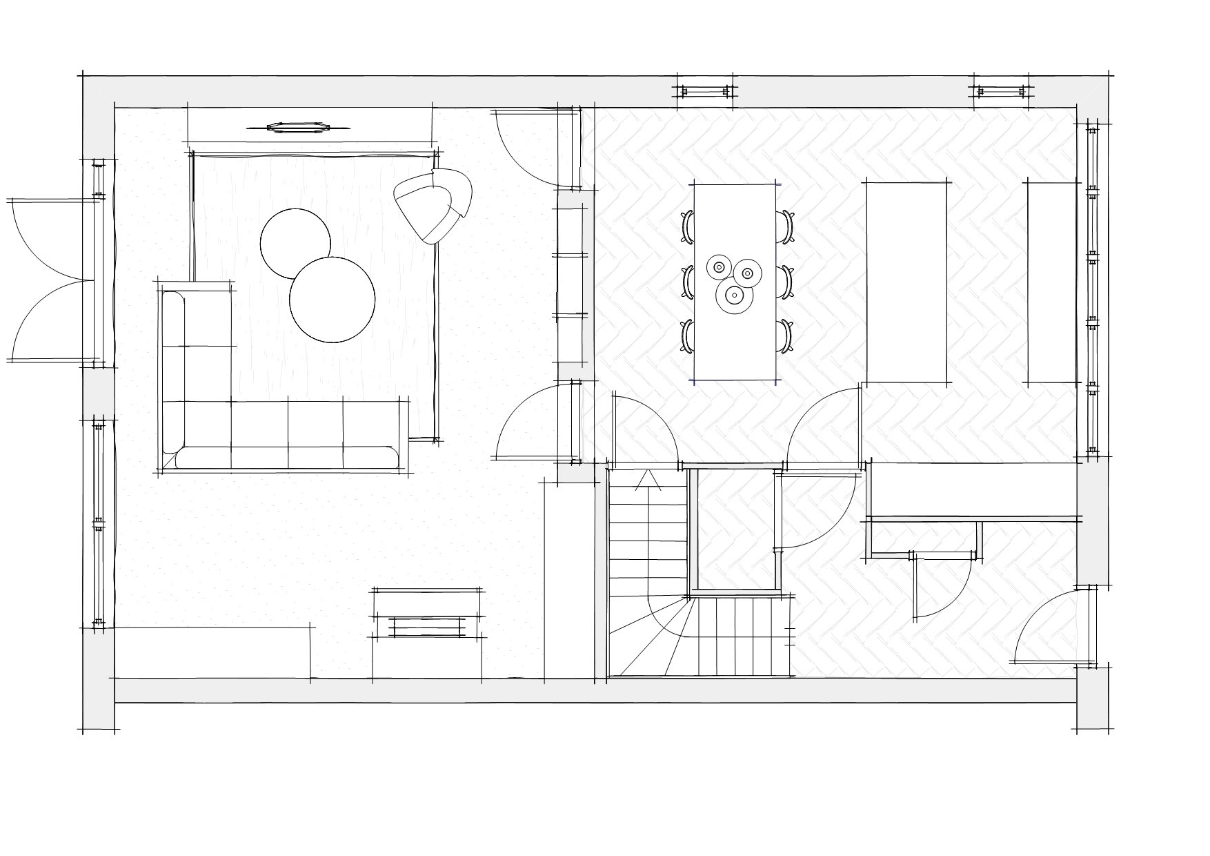
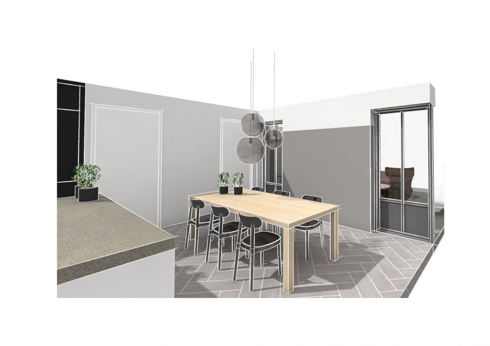
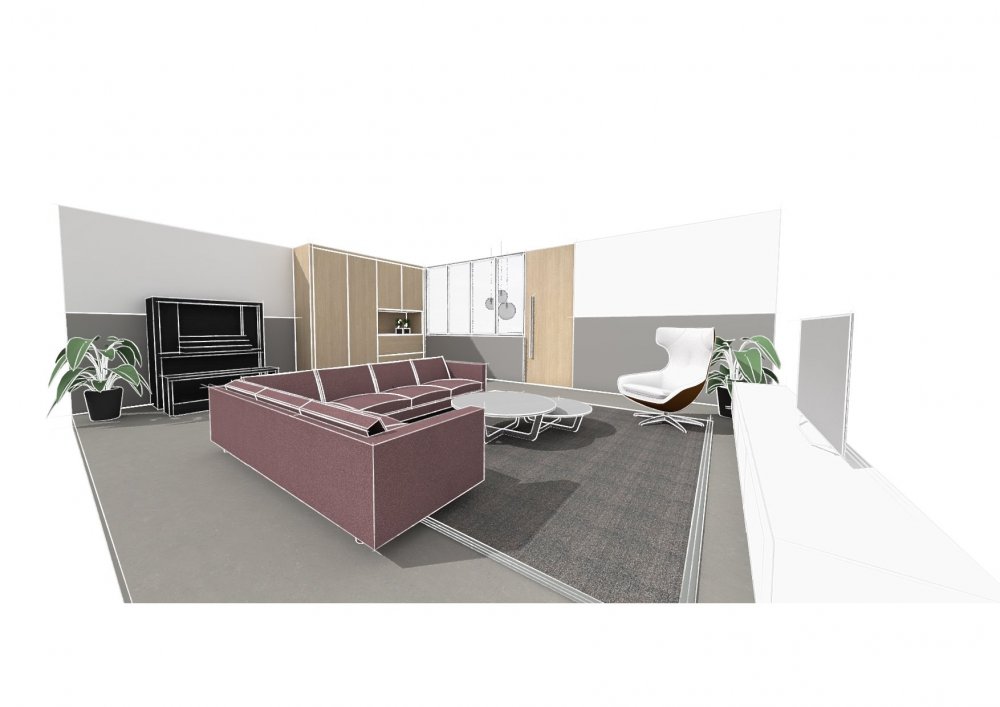
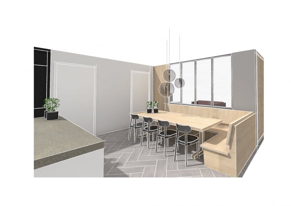
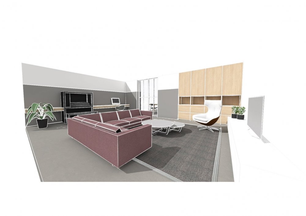
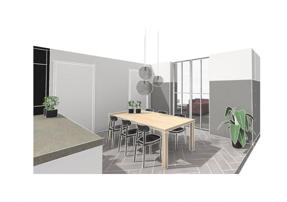
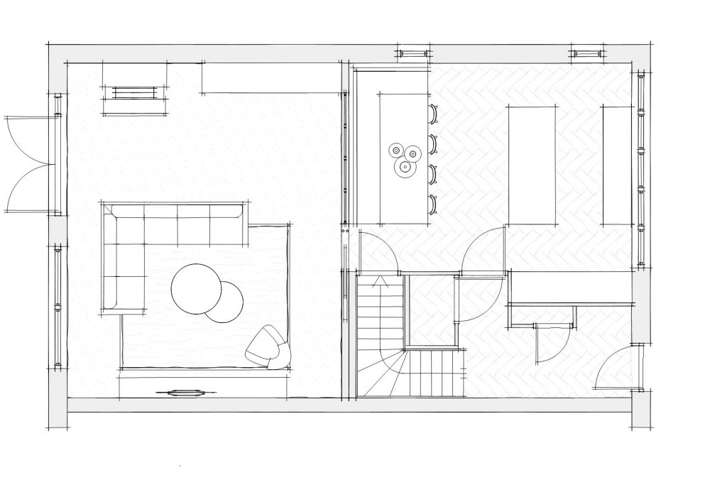
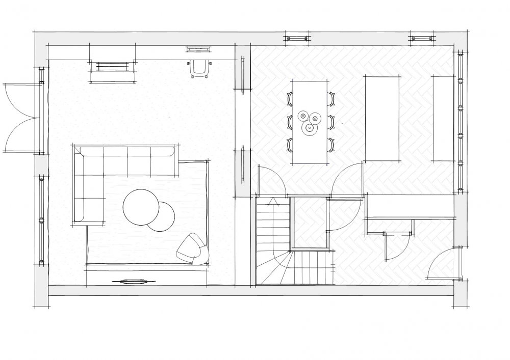
So I thought to share some new renderings I made for another interior project we are working on. In render style it is pretty the same as the last one I shared. It is good to see that for the sketch fase you can do the whole process in Vectorworks. For the next fase i would probally go to C4D > corona. The render quality in VW is kept pretty low (lighting / textures / blurriness) and there is not allot of editing of details and textures, but the sketch lines masks this 'lack' pretty well. Overal I`m very pleased with the time it took to create the renderings and the time it costs to render them (lighting/textures in 2 a 3 minutes, sketch lines around 10 min what I thinks is a bit to long). Especially pleased with the custom cabinet plugin for creating quick and dirty cabinets in just a few clicks. Importing the furniture cost the most time because of putting everything in the right classes, and give them a 'okay' texture etc. If you guys have a good and fast workflow for this I would love to hear it. About the design: It`s a new house being build as we speak where the owners asked for some interior ideas for the now combined kitchen and living. We made three options. All included a new separation between the living and kitchen area so there is the possibilities to use the rooms at the same time for different activities (studying in kitchen and gaming in the living room for example).


- 31 replies
-
- 9
-
-
- renderworks
- rendering
- (and 1 more)
-
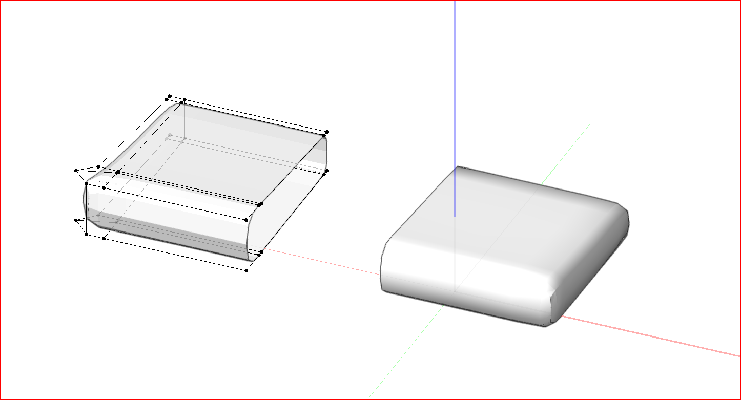
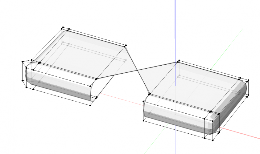
The object I want to model is less 'mirrored' then it seems, so I would like to do it without mirroring. Bridging the object works, only it seems that the bridges flips over to the other corner in this case so you get this strange cross you see in the screen cap above.
-
Okay so I found a way to do it by composing the two subdivision object (1: select objects 2: modify menu 3: compose command) Now I run in to this problem when bridging the gaps: Is there a easy way to solve this?
-
I was wondering the same. Is it possible to bridge the two separate subdivision object in the attached print screen? The file is attached. combine.vwx

-
Jim thanks for all your help and honesty on this forum! I hope your colleagues did something special today for you 🙂 Wish you all the best for you and your family!
-
The unfold command works with nurbs surfaces. Select a nurbs surface and use this commmand to unfold it. The command only works on single curved surfaces. Does that help?
-
Sometimes the command 'sits' under the 2d command when you click on it. Otherwise you can add to your worksspace. I use it regularly
-
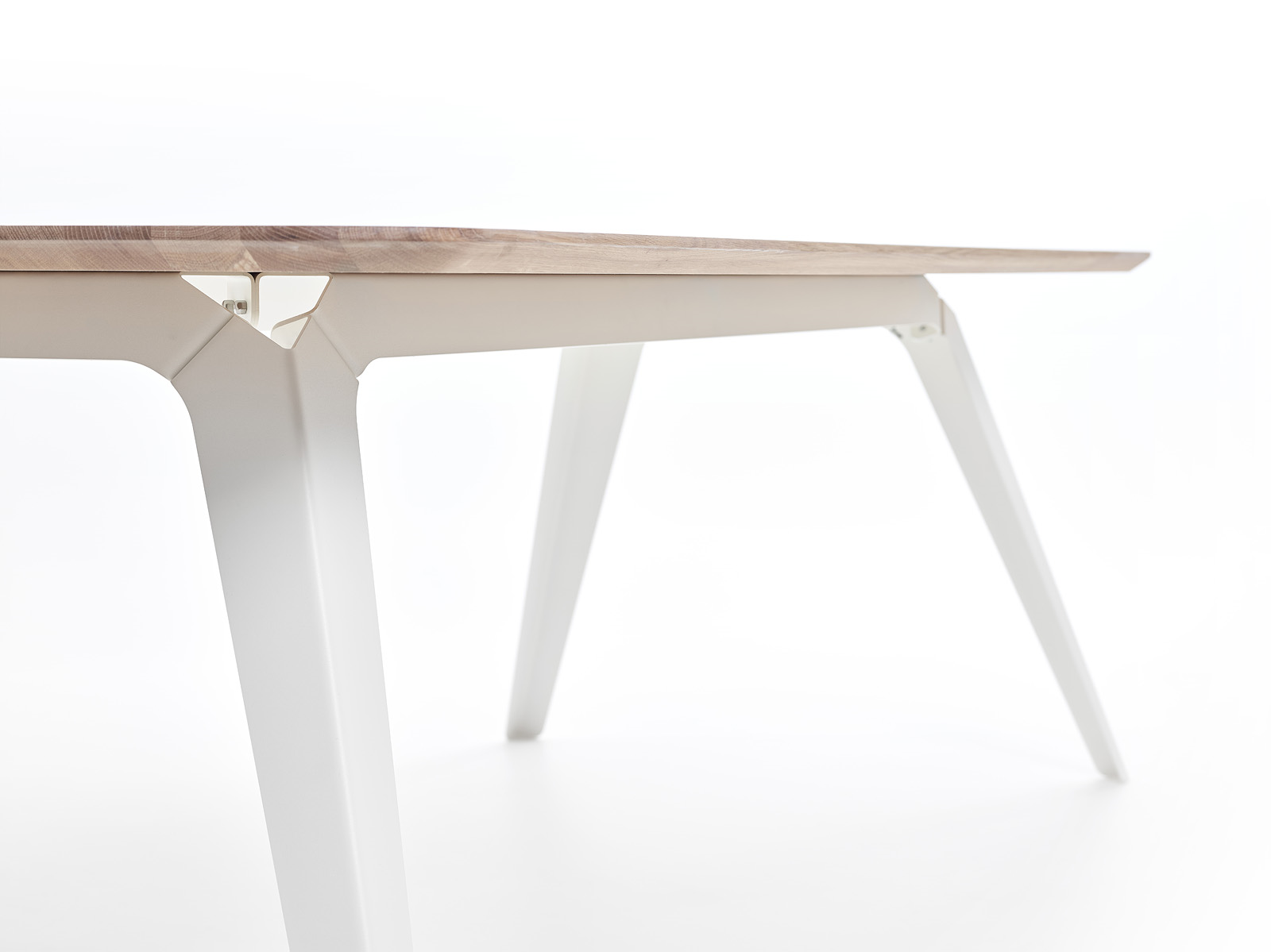
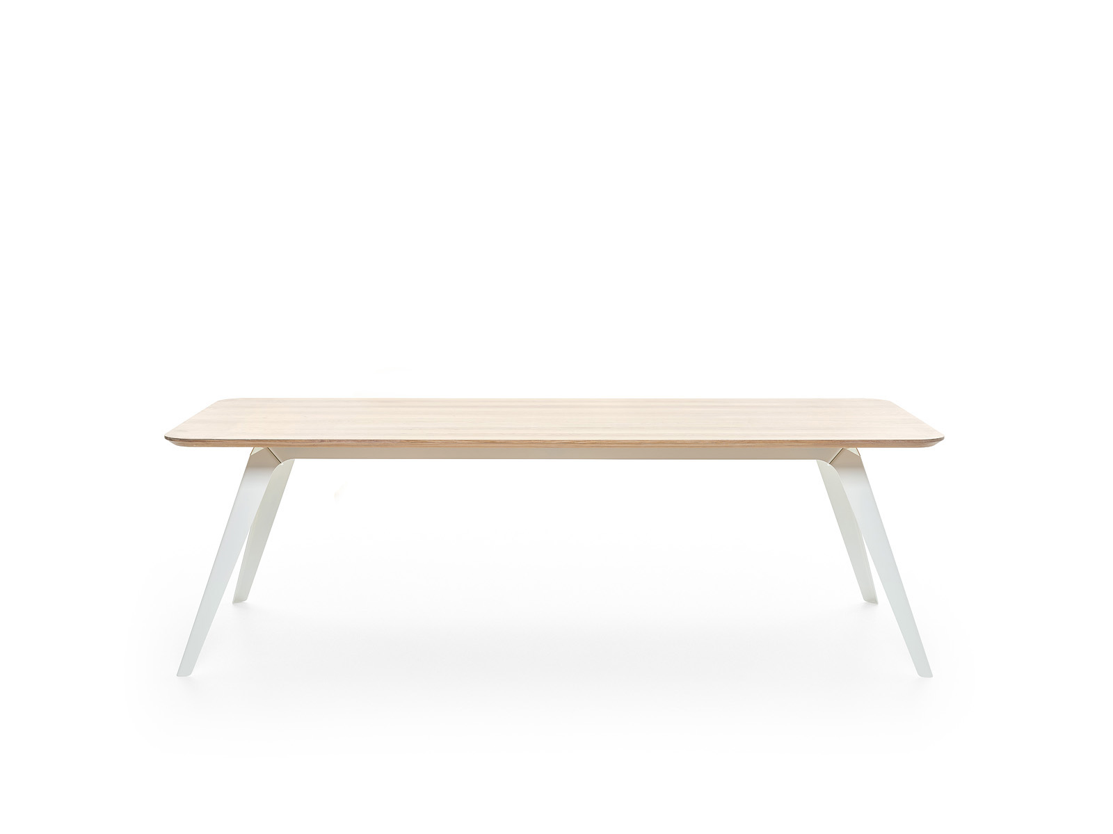
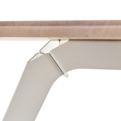
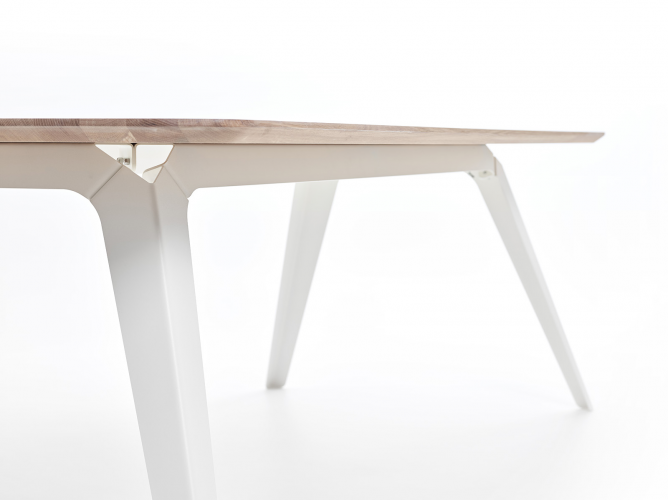
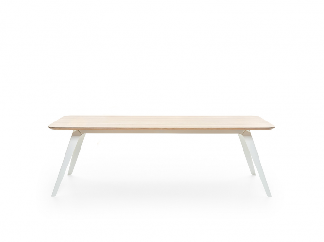
Okay here we go 🙂 The best way to do this in my opinion is: Creating the box: 1: create all the faces of the box in planar rectangles or polylines and create the wanted box. 2: use ctrl+alt+k (create surface from curves command) to convert them to 3d nurbs surfaces. You can only do this one-by-one. 3: use ctrl+alt+y (create fillet command) to create the inner diameter of the nurbs surface by selecting two intersecting faces of the box. For this command you should align the normals to the inside of the box. This you do for each individual fold. 4: use shift+g to shell all the created nurbs surfaces to the outer side of the box, for example 3mm. Now you have you box in 3D. Extracting surfaces: 5: If you want the middle line of the metal flat plan the you have to adjust the shell to 1.5mm in this case. 6: use shift+ L to extract all the surfaces and set the preference to 'create planar object'. 7: now you have to unfold curved surfaces with the command 'unfold surfaces' from the 3D power pack in the model menu in the top bar Create flat plan: 8: select all the planar surfaces 9: set your view to top/plan 10: set in the OIP the 'Layer plane' of the selected planar objects to screen and then again to 3d > this put all the planar objects on the same plane and height 11: with all the planar objects selected set the X and Y in the OIP to 0 and 0 > this put all the objects to the centre of the drawing, sometimes they are far away 12: puzzle with al the faces till you get the right flat plan of the box 13: use the command 'add surfaces' from the modify command. 14: tada! you have a flat plan! 🎉🎉🎉 Its allot of steps to do sheet metal, but possible in Vectorworks. Versatile Vectorworks! I designed several tables with this proces, and with the principal 'no screw, no glue' in mind:
-
 Width and Height work perfectly. Length returns 0 if you set the criteria to Symbol unfortunately. VW help says Length is for path based objects, so I thought maybe there is the possibility to use Depth or another formula? Length(criteria): The length of lines, walls, or path-based objects that meet the specified criteria. Examples: ● Database header cell: =Length returns the length for each object in the database ● Spreadsheet cell: =Length(t=line) returns the total length of all line objects in the drawing
 -
I tried this on symbols and it give the width and height for symbols, which is great, but it gives a 0 for the length. Is it possible to get the 'depth' of the symbol in a worksheet?
-
Records that work as a symbol
Bas Vellekoop replied to Bas Vellekoop's question in Wishlist - Feature and Content Requests
This is how I do it know, but I would like to eliminate this step and make it an option in the 'edit symbol option'. -
Records that work as a symbol
Bas Vellekoop replied to Bas Vellekoop's question in Wishlist - Feature and Content Requests
Thanks for that suggestion. What I ran into doing that: It is very easy to give different symbols by accident the same name/number in the 'data tab' of the 'OIP' and mess up the partlist or bill of materials. When you are working on new project this is not the biggest problem, but after 6 month doing some editing or changes... So that's why I was looking for a way to use the symbol name, because you can`t give them the same name. side question > There is no way of pulling the symbol name in the record format? -
Records that work as a symbol
Bas Vellekoop replied to Bas Vellekoop's question in Wishlist - Feature and Content Requests
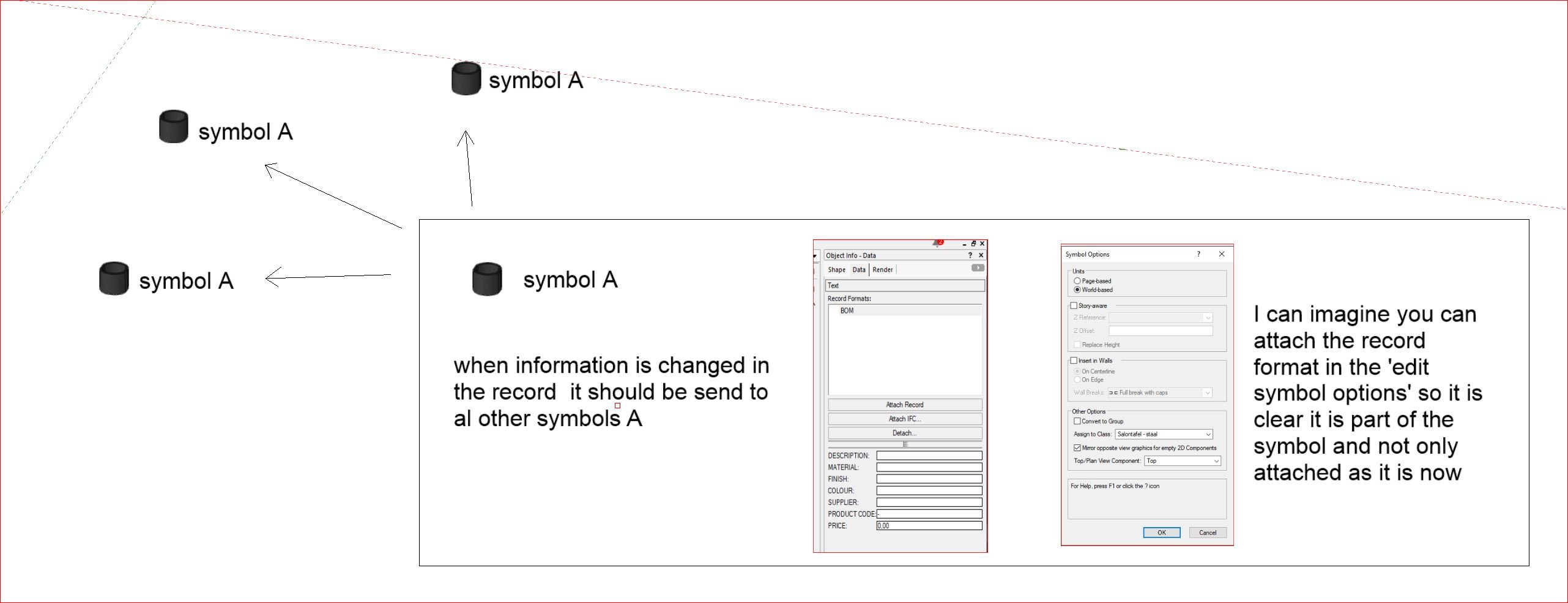
What I want to create is a worksheet with in the first column the symbol name, and in the other columns info from a record format. See attached file and screenshot. In the worksheet I want to be able to change the info of the record format so it goes to all symbols with the same name. I want this to work as well when changing info in the 'data tab' of the 'object info palette' of this symbol. So it should be a 2 way street and send the info to all the symbols. Makes this it a bit clearer? symbol name and record information in a worksheet.vwx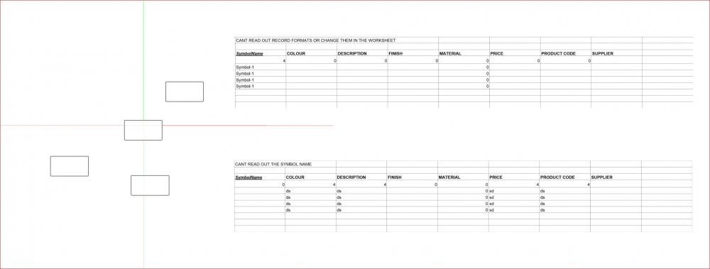
-
Records that work as a symbol
Bas Vellekoop posted a question in Wishlist - Feature and Content Requests
It would be great if we got the option to attach a record to a symbol with the possibilty to distribute the edited information in record to all other symbols with the same name. At the moment the only way to change the information in the record and distribute it to all the symbols is through a worksheet. This is not ideal, because 90% of the time you don't have the worksheet open or ready when you are editing info in the data tab of the OIP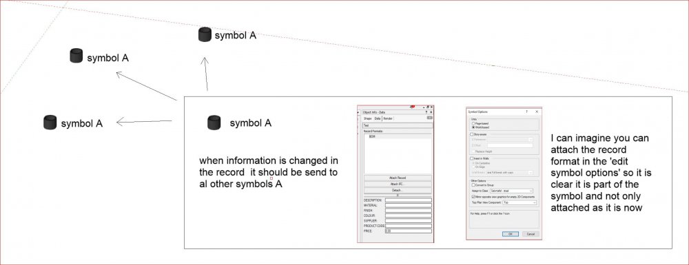
-
Creating Symbols with Drop Down Attributes
Bas Vellekoop replied to HSTEW's question in Troubleshooting
There are several PIO that can do this. You can change the type of the screw the size etc. in the pio. In 2d and 3d as separate modes. I hope there is a pio that suits you. The link is one of them. http://app-help.vectorworks.net/2019/eng/index.htm?#t=VW2019_Guide%2FDetails1%2FScrews.htm%23TOC_Lag_Screwsbc-1&rhsearch=Details&rhsyns= &rhtocid=_11_0_7_0 -
So many ways in VW, forgot about the EAP 👍
-
As far as i know this is not possible. But would be a great addition to VW if possible
-
I tried to convert a extruded circle to a subdivion object and then move the top. But VW can not convert it to a subdivision unfortunately. A: A multiple extrude can do what you ask, but is 'heavy' object in VW. It can slow down your file. B: Otherwise you could: draw te circles (circle tool or shortcut '6') place them on the correct height (ctrl + alt + M) convert them to nurbs curves (ctrl + alt + n) loft them in the first mode (3d modeling toolset) create planar caps (3d power pack) stitch and trim surfaces (3d power pack) C : The deform tool maybe, but i didnt get it to work. I got it too bend, but it did not shear in my quick test. Attached a simple file with some tests multiple extrude.vwx
-
Extrudes shouldn't "remember" rotations
Bas Vellekoop replied to Andy Broomell's question in Wishlist - Feature and Content Requests
Please dont remove the history of extrudes. From me this is one of the best features of VW. -
Associative Dimensioning on 3d models
Bas Vellekoop posted a question in Wishlist - Feature and Content Requests
Almost everything gets modeled in 3d these days. Associative Dimensioning is only possible with 2d geometry in Vectorworks. Is wish it was possible on 3d geometry as well. The following tools should be able to recognize 3d geometry in models and work associative on sheet layers and design layers: - Unconstrained Linear Dimensioning - Constrained Linear Dimensioning - Dual Dimensioning - Radial Dimensioning - Marking Object Centers - Angular Dimensioning - Arc Length Dimensioning Vectorworks should be able to recognize radial dimensions and curves on shelled nurbs surfaces and perfect round extruded polygons. Attached I have a file I wish VW could dimension associative and would be able to recognize al the different dimensions. Pleas pitch in for enhancements on this wish. Associative Dimensioning.vwx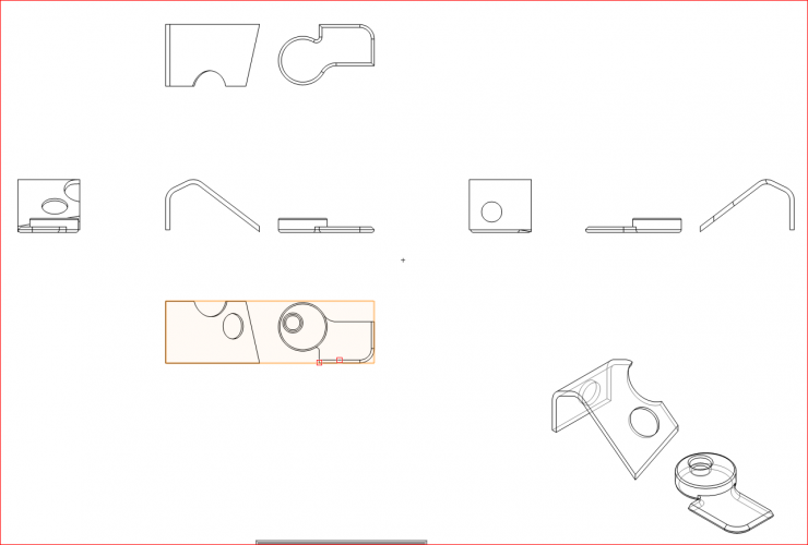
- 7 replies
-
- 12
-
-
- associative
- dimensions
- (and 2 more)
-
You could create a simple worksheet and make it count al the symbols in your drawing. In this way you easily see of which one there is just one, and of which ones there are more then one. From the worksheet you can select each individual symbol of which there is just one and convert it to a group. The only downside is that you can not select all symbols with just one instances at the same time (as for as i know) So you have to select every symbol and convert it by hand. But maybe someone can create a simple script to convert all single symbols...
-
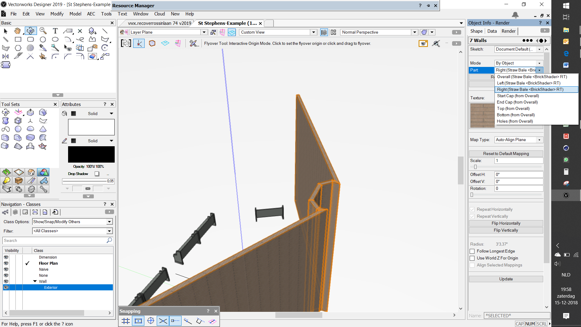
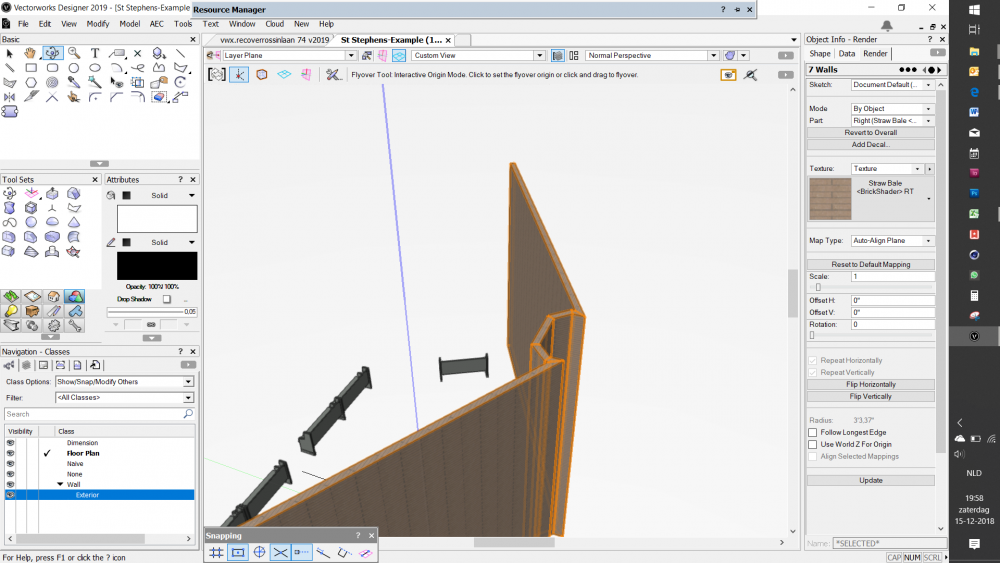
When you go to the render tab of the the object info palette you can change the texture of the individual parts. This solves your problem. But I would recommend to create walls with components and for each component a individual class so your can control those through classes. ut i would

-
@Scott61 Could you share the wall in a file so we can have a look?
-
maybe it is useless but... A : what if you: 1 - create a separate layer for the chimney where you model the whole thing 2 - create your regular layers for your first and second floor without the chimney. 3 - create 2 design layer section viewport of the chimney layer for both floors on the correct heights 4 - put the design layer section viewport in the correct place on the floorplans Another option: B: Something else i noticed is that you can create 3d symbol of the chimney. You can paste the symbol on both layers and adjust the Z value of the symbol so it is at the correct height. On each layer you now can create an auto hybrid of the symbol. If modeled correctly this should show the correct 2d plan. (at first sight there are no problems with coplanar faces in Opengl if both layers are turned on) Both maybe totally useless, but Vectorworks seems to be so close 😂 chimney test.vwx