


Bas Vellekoop
-
Posts
651 -
Joined
-
Last visited
Content Type
Profiles
Forums
Events
Articles
Marionette
Store
Posts posted by Bas Vellekoop
-
-
On 1/14/2022 at 7:55 PM, Guest Shengxi Wu said:
I believe operation at group level was proposed in the original design for batch processing. For some reason (probably because of the minimum viable product requirements, or might be technical challenges), we decided to not go with it. Anyway, we will investigate if that is possible in case that resolves Kaare's concern.
I can't reproduce it. Could you attach a sample file so we can look into that? Thanks Andy.
Any change that this still gets implemented on grouplevel? Would be very handy indeed 🙂
-
 1
1
-
-
10 minutes ago, Tom W. said:
Is there a comprehensive list of new features somewhere?
Like this one for VW2022: https://app-help.vectorworks.net/2022/eng/VW2022_Guide/LandingPage/New_features.htm#h
All I can find is this: https://www.vectorworks.net/en-US/public-roadmap/updates
Here you go 🙂
Loving all te new features!
-
2
-
-
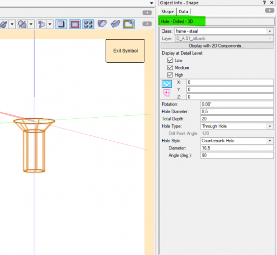
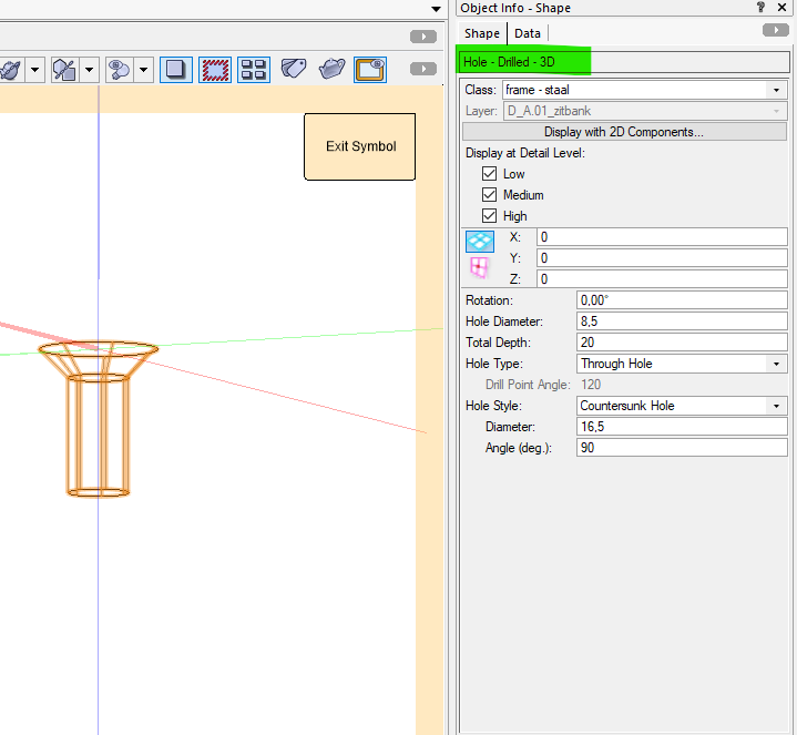
Since version 2021 or 2022: if you make a symbol of the 'hole - tapped' object then you can change al the made subtractions by editing the symbol. Ideal because you cant forget one. (Instead of going into the different solid substractions and having to edit them one by one)
-
1
-
-
-
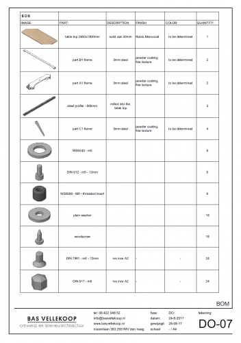
The new material resource is probably the way to go in combination with worksheets.
In the past for product design i used it quite allot as can be seen in the attached picture. Then i used symbols and classes to get the right objects in the worksheet. This example is a sofa. But i used ut for the calculation of the weight of chandelier as well. It's good to know if the electric cord wil hold it 🙂

-
12 hours ago, Bruce Kieffer said:
I do agree there are some parts like screws and biscuits that are great as symbols, but not wooden parts, at least not until the design is completed. And I did try adding records to give me the info that Vectorworks is confused about. The problem with that is it's me entering the data, and if I make a change to the size of a part, then I need to also change the record. I use a worksheet to count objects, but I use Apple Numbers to make material cut lists.
For screws etc it is great. For other parts of the design in my experience as well.
With the option 'show other objects while in edit mode' editing is as easy as it would be just an object in the drawing. Its just right mouse click > edit 3d component
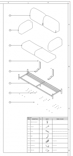
With the creation of symbols of all the different parts of an (sub) assembly it is fairly easy to create separate design layers where you put each individual symbol on.
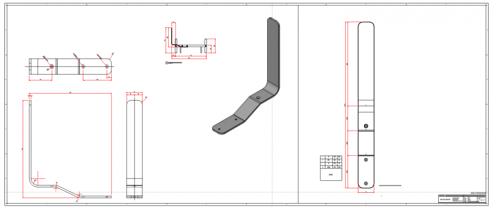
You can use these design layers for easy for editing (if needed), and they are ideal for setting up sheet layers of each individual part for annotating and dimensioning.
The only thing I`m really missing is auto updating dimensions as in Fusion 360 or other more product design focused programs. auto updating dimensions would save allot of time and possible faults.
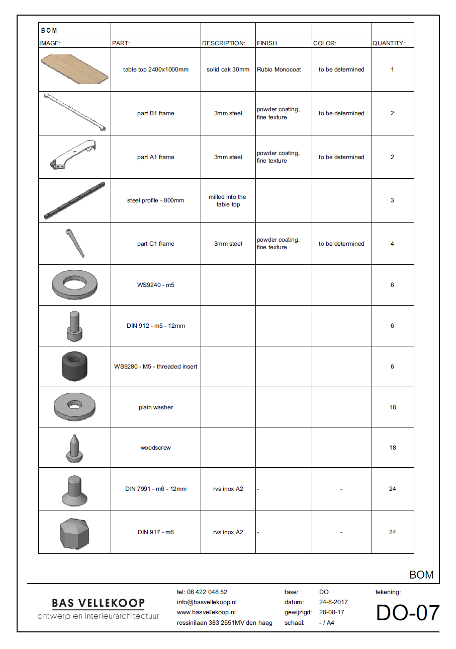
Automatically filling record or worksheets with length height with is not possible, but records for the creation of a Bill of Material can be very handy.
This is a fairly simple one:
In combination with Data tags and design layer viewports it is even more fun 🙂
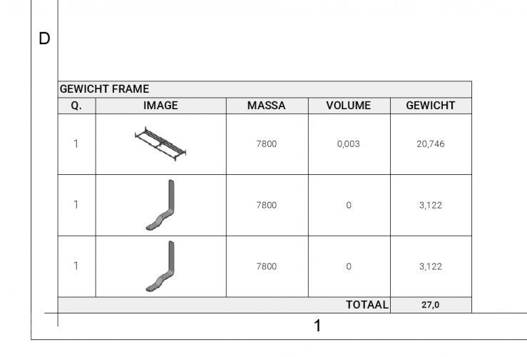
And with some simple math you can get weight of your design and can change your design if that is needed based ont that.
And if you just want to show and annotate parts and create flat patterns with the bending lines etc. 🙂 :
So allot is possible with symbols 🙂
-
2
-
-
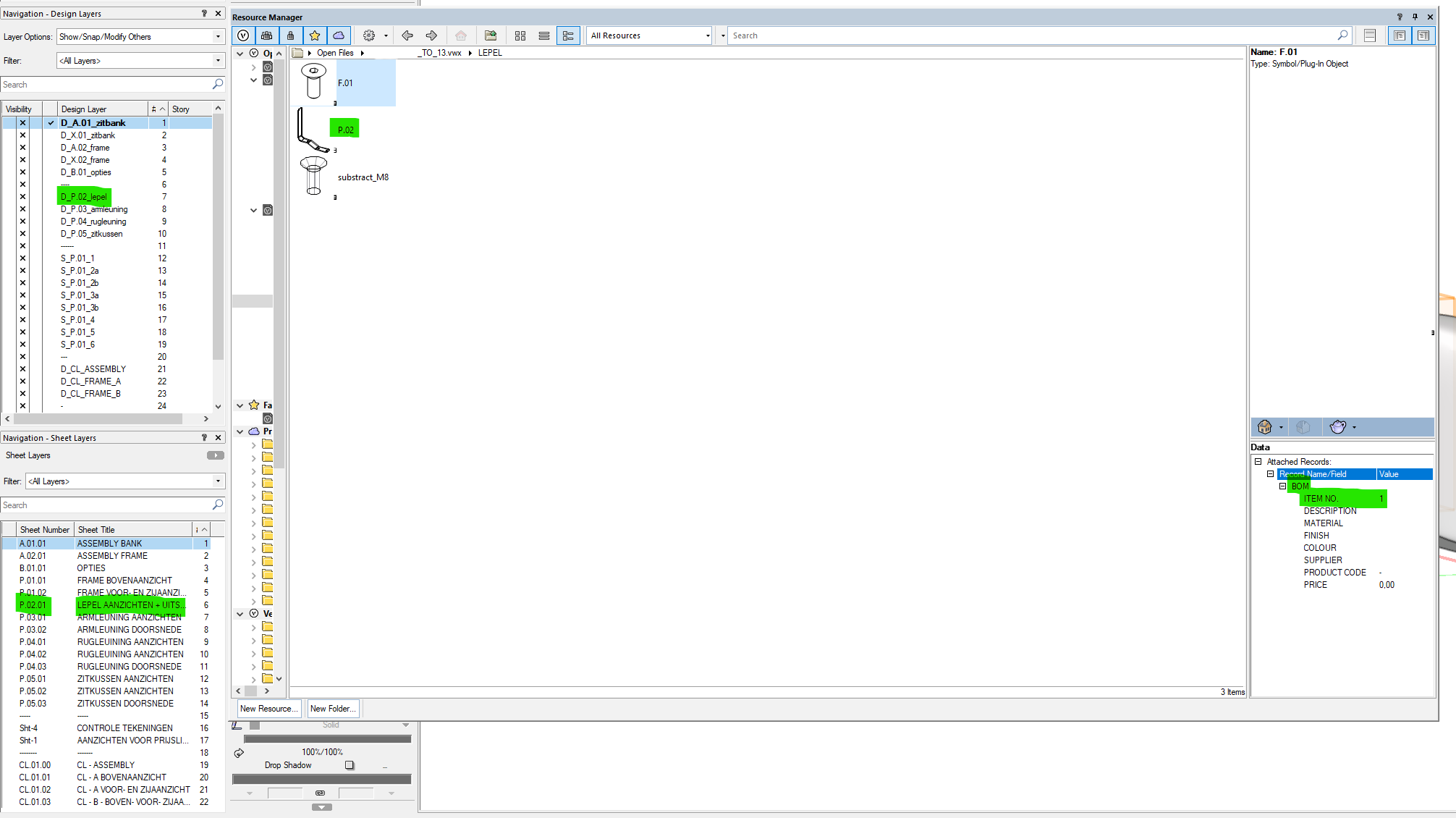
When i did furniture design in VW I made extensive use of symbols. I would highly recommend it.
I created a system where symbols < > design layers <> sheet layers correspond with each other.
You have to keep your file clean and organized, but it works pretty great.
All my parts had a P of product, all subassemblies an SA, and assemblies an A. following with a number.
Attaching a record format to the symbols creates the possibility of the creation of Bill of Materials with costs, finish, supplies etc.

Now with the new modeling possibilities this workflow is even better. For subtractions you can now use symbols. If you use the hole tool in a symbol you can change every hole in just two steps. Vectorworks will update all subtractions where this symbol is used automaticlly 🎊🎊🎊
Attaci
-
1
-
-
@The HammaIf you could vote this up with the arrow at the top of this page, that would be great!
-
55 minutes ago, Pat Stanford said:
I don't see any way to get any attributes of an object into a data tag, so the answer is probably no.
Having and Attributes data set including Color names and line styles would probably be a good wish list item.
Done 🙂 , please vote up 🙂
-
2
-
-
I would be a big time saver if it was possible to get the names of the object attributes in a data tag.
A - The names of the fill styles:
- solid > color name
- hatch > hatch name
- pattern > pattern name and foreground and background color names
- tile > tile name
- gradient > gradient name
- image > image name
- when the fill style is set by class then then specified name in the class fill style
B - The names of the pen styles:
- solid > color name
- pattern > pattern name and foreground and background color names
- line type > name of line type and name of color
- when the pen style is set by class then then specified name in the class pen style
C - The line thickness
D -The number of the marker
Usercases: part B of this discussion:
-
3
-
Hi all,
Is it possible to get the color name of a fill in a data tag?
Any help appreciated! 🙂
-
18 hours ago, Pat Stanford said:
I don't believe it is possible directly. Worksheets are only able to see objects that are present in the file (from a programming standpoint, objects that have handles in the drawing space). You might be able to apply the textures to objects on an extra layer and then get the information, but I have not tried it.
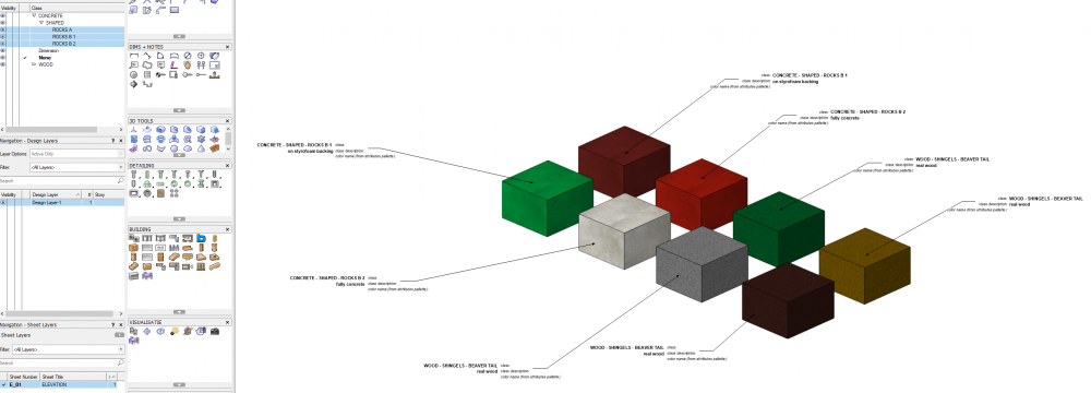
Besides the worksheet: Would you think it would be possible to get the color name (the color name that is available in the color palette) in the in a Data tag?
tagging @Wes Gardner as well because he seems a master in data tags 🙂
The way I would like to use it:
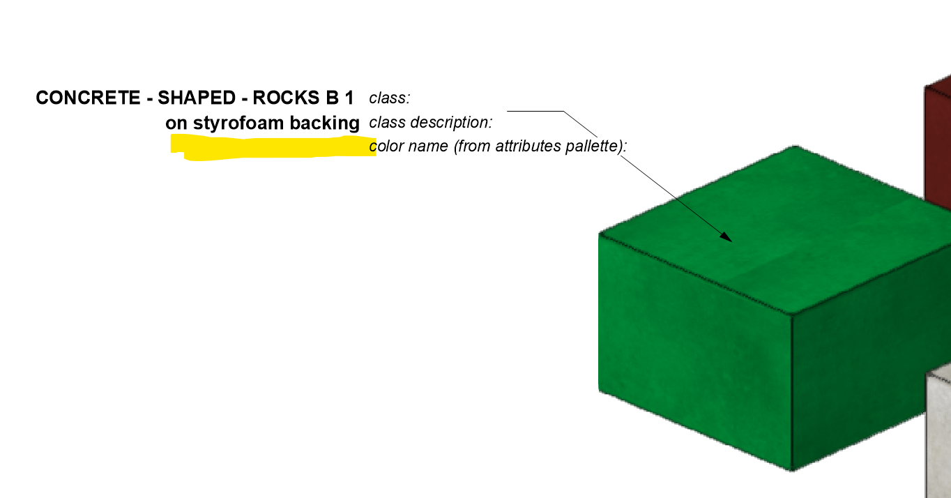
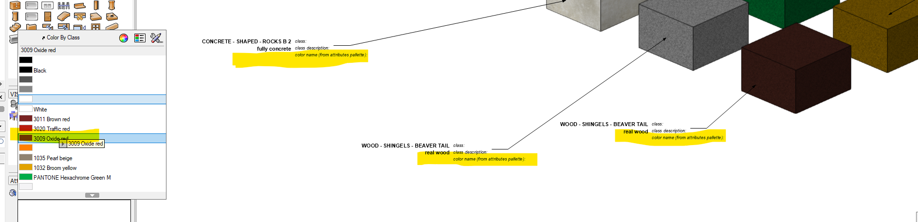
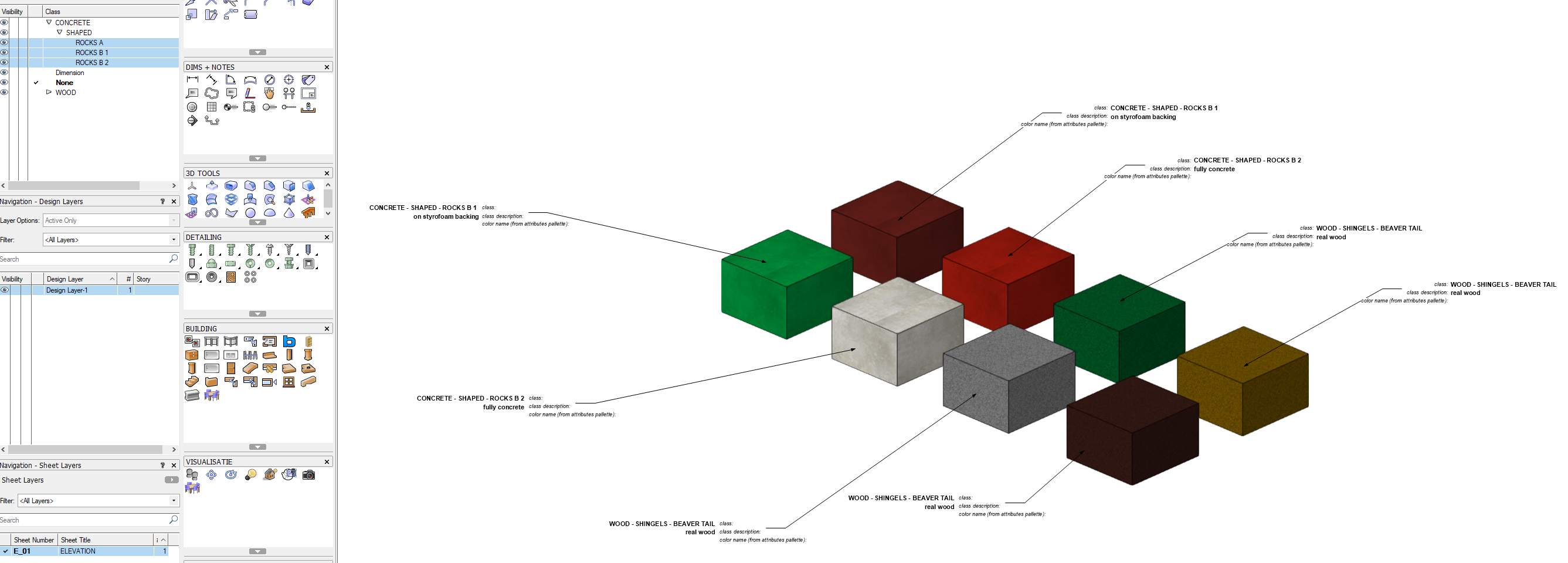
I have a big project with 10 different types of materials. These 10 materials can have all the colors available in the RAL color coding system.
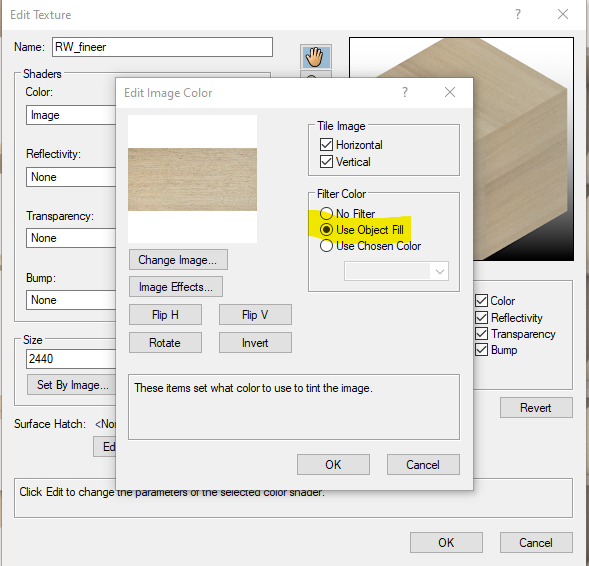
In order to prevent that i have to create all the classes for the 10 materials and the hundreds of different RAL-color I thought of setting the color of the material by the object fill in the attributes tablet.
By doing it this way I can prevent the creations of hundreds of classes and can color object every object just the way I want.
And if I can use a data tag to get the object fill / color name in a elevation i would be really happy 🙂
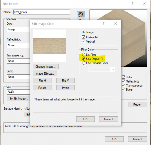
1: Set the color of textures by 'Object Fill':
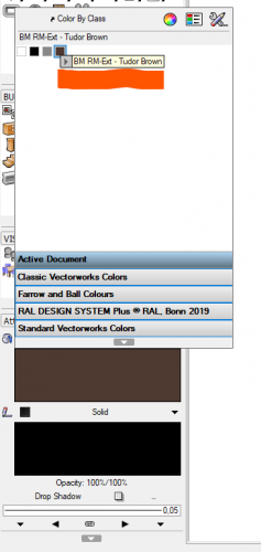
2: Use the Attributes Pallete to override the standard color with a custom RAL-color
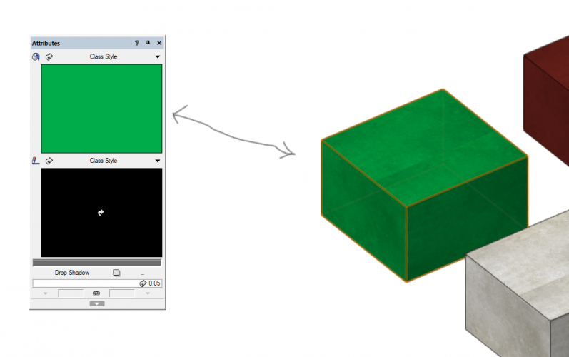
3: get the color name in a elevation with the use of a data tag:

Would this be possible?
-
Hi all,
2 questions:
A:
I`m wondering if it is possible to get Renderworks textures in an worksheet with an image of the texture.
The idea is to create elevations with data tags which refer to a worksheet for the: material, texture, color, ...
B:
Is it possible to get the name of the chosen color fill in a data tag?

-
@Nikolay Zhelyazkov Thanks!
Yeah i got it by some fiddling around, missed this at first.
For anybody with the same question:
-
2
-
-
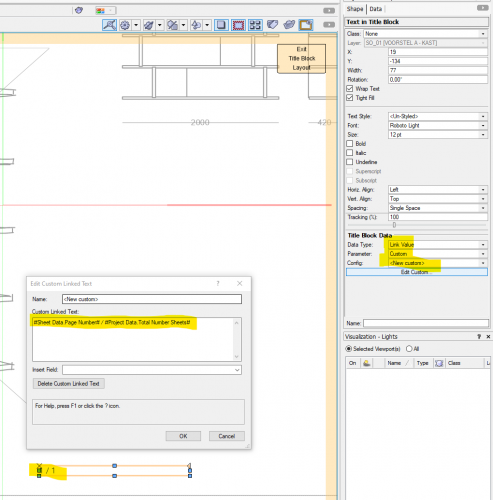
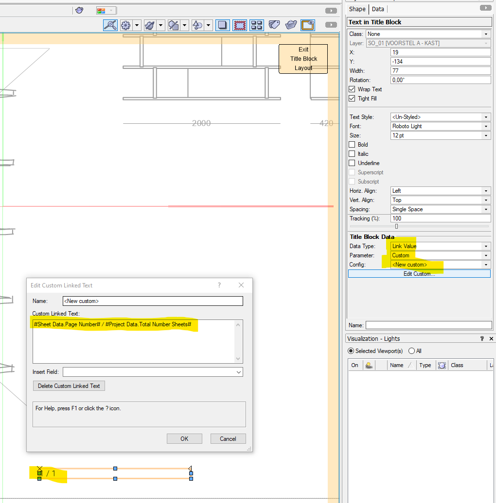
Hi all,
I`m wondering if it is possible to create a title block with gives you the following for page numbers: page number .... of a total of .... pages.
So when there are twelve pages and showing page number one: 1/12
Is this possible?
-
4 minutes ago, Senthil Prabu said:
@Bas Vellekoop @Stephan Moenninghoff while updating all the instances of the edited symbol, the system will rebuild the top level CSG if it is inside it.
Very good! For modeling non architecture stuff this is amazing (tables / custom cabinet s / some custom project specific fixtures etc )
-
2
-
-
- Popular Post
- Popular Post
So i thought this happend a few weeks ago, but no i double checked and this is freaking amazing!
We can model parametric with symbols within solid additions, subtractions etc.
I have seen no mention of this feature what so ever, but this is really big!
Thank you!
@JuanP @Stephan Moenninghoff @Gunther @mjm
See attached video
-
6
-
2 minutes ago, JuanP said:
The next live session will start in 48 min if you would like to attend: https://www.vectorworks.net/design-day
I would like that, but their is dinner on the table in 40 mins where i will be expected, life choices 😄
-
-
1
-
-
A workaround i found is the use of Design Layer Viewports for an assembley of symbols. This way you do not need nested symbols
1 create the needed symbols
2 create a separate design layer 'assembley truss 01'
3 create the assembly of the symbols on the design layer
4 make a design layer viewport of your assembly and use this on your main design layer
Now you can still tag all of your symbols that are used through the design layer.
I do not know if this gives you a performance hit. Maybe DLBP's are slower then a symbol with nested symbols?
-
23 hours ago, Bruce Kieffer said:
Is there a way to see in the OIP the Z height of an object no matter what type of object it is? Every object resides at defined coordinates in space on y drawing, yet I can't see those coordinates easily, and I want to.
A Z-height for everything would be great!
Maybe a wishlist-item for this?
-
Almost everything in Vectorworks can be ungrouped. Design Layer Viewports can not.
Wish:
Ability to ungroup Design Layer Viewports so it imports geometry to the design layer where the viewport is on. This should be possible from within the document (from another layer) or an external document.
Additional it would be nice if specific parts (objects / layers / classes) of a viewports could be imported into the model.
-
1
-
-
3 hours ago, Stephan Moenninghoff said:
No trouble at all!
1. Yes. You can tell your Marionette to do whatever you want it to. (Always remember that you may need to regenerate it though!)
2. Not for me to say.
The exclamation point makes it seem that i should know what 'regenerate' in this situation means, I do not, please help 😂
-
17 minutes ago, Stephan Moenninghoff said:
Even if I did, it has nothing to do with how VWX implements anything 🙂
Sorry, I do not get it I think 🙂
If I was unclear then let me try to rephrase it.
1. Is it through a script or Marionette possible to create some sort of button that makes Vectorworks recalculate the CSG solids that are present in the VW file?
2. Would through an VW enhancement request it be possible to add this as an automatic part of History-Based Modelling? (Vectorworks recognizes you changed a symbol that is used in a solid addition or subtraction and recalculates the CSG solid automatically?
Thanks for your help and patience 🙂


.step-files
in General Discussion
Posted
Nope, there is not.
(For these kind of things I switched to Fusion360)