


VvierA
-
Posts
182 -
Joined
-
Last visited
Content Type
Profiles
Forums
Events
Articles
Marionette
Store
Posts posted by VvierA
-
-
Hi there,
I really like the data visualization feature.
The problem is, that it is not possible to combine data visualization with overriding class attributes in a viewport.
But this is exactly what I would need most of the time: visualization of data in a drawing that is apart from that graphically defined via class attributes.
The solution would be so easy: data visualization should simply override the attributes of the specific classes that are affected and for the rest the settings for the class attributes of the viewport should be valid.
What do you think?
VvierA
-
 1
1
-
-
Hi Marissa, thank you again, very helpful and interesting...
do I understand it correctly your new choices node gives to results: i is the integer representing the number of the option in the list and s results the string?
So I can still use 'i' for a comparison in a valve node and 's' to write it in my record field...
-
Hello everybody,
with the kind help of Marissa and the forum I managed to create a working network.
There is a pop-up list at the beginning to choose between some options, for example 'timber, concrete, glass'.
Now I'd like to attach the name of the chosen option to a record field, for example create a record format 'custom object' with the field name 'material' and attach the chosen option 'timber'.
I've found some nodes (i.e. create field) that seem to be helpful but I didn't find an example on how to use them the right way...
And I was also wondering how to get the name of the chosen option of the pop-up list. I don't know how to do this, because the result of the node popup is just a integer number that represents just the position of the option in the list.
Does anybody know of some examples or can anybody help me with some hints?
Thank you
VvierA
-
Yes, it's the German version.
Do you know of some kind of workaround, until the network works with non-English versions?
-
Hi everybody,
I was looking around a little bit about information on how define the linestyle of an object.
There is a Linestyle bug thread but it doesn't help.
If I try to run the network Marissa provided in the last post I get an error message.
My task seems to be easy: I'd like to define the line style for a polygon. But how do know the index numbers for the self defined line styles in my document?
Thanks
VVierA
-
My network creates two polygons, that overlap partially. I want one specific polygon on top of the other and I'don't get it...?
On 1/19/2016 at 5:50 PM, J. Miller said:just experimenting...
I used an "ordered list" data flow node and placed the 2D objects in the order i wanted them to be drawn. it worked just fine
Jeff
Maybe I missed something, but it didn't work. I placed a 'ordered list' node at the end. Connected the polygon to be on top to item0 and the second to item1 but it doesn't help.
On 1/31/2017 at 3:51 PM, sbarrett said:When I have several objects that are created by a network and can't be ordered the way I want them initially, I will put them through an ordered list at the end, then through a group node, then an ungroup node. This will put them in the correct order as well as a single Marionette group.
I added a group node and an ungroup node but it still doesn't work.
Can anybody help?
Thank you all
VvierA
-
That's it - thank you again, Marissa. Sorry to bother you with such simple questions. Your help is very appreciated.
-
Thank you - the trick with deleting the first line worked. But the popup list still doesn't appear in the OIP.
-
Oh and another issue...
If I just use the sample with the three choices and I convert my network into a Marionette object the three sample choices do not appear in the OIP.
Is this, because it's just a sample and does the popup up list appear automatically if I manage to change the sample entries?
-
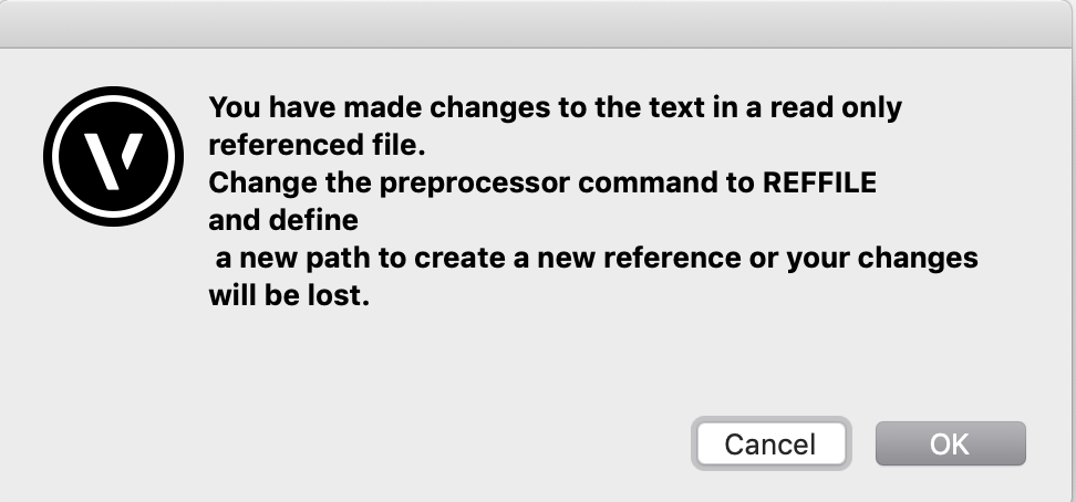
Thank you. So I understand, that I need to edit the python code of the node?
I tried to do this to make changes, but it doesn't work. When I made the changes and closed the python script window it tells me 'You have made changes to the text in a read only referenced file....'. I don't know how to duplicate the node template and how to remove the write protection so that I could edit it.
Maybe I got something wrong?
-
Thanks you so much Marissa. The symbol works fine.
Sorry to bother you again, but I have so many questions...
I'd like to implement a PopUP Menu with some options in the OIP of my Marionette Object.
I already found the Popup Menu node. It offers three choices, but there is no direct access to edit the number or the names of the choices.
Do I need to edit the code of the node to configure it for my purposes or is there another way?
-
Thank you very much for the quick response, Marissa.
I learn that trying to 'transfer' the code that was generated by Marionette to a PIO might not be the best idea.
Instead - what do you think is the easiest way to make the Marionette Object available in every Vectorworks document as a kind of tool?
I'm wondering because I didn't find a way to share the Marionette object other than opening the VW document where it is placed and transfer it by copy and paste to another drawing....
-
Hi guys,
I created a Marionette object and I'd like to convert to a custom plugin.
Is there a simple way to do it?
Or is it maybe possible to just copy the code of the marionette object and create a custom plugin object manually?
Thanks in advance
VvierA
-
Hi everyone,
I think data visualization would be a very helpful feature. For my purposes it's odd, that it is not yet possible to combine data visualization with custom class attributes for viewports.
For example:
We like to use custom class attributes in layout viewports to adjust the graphical appearance of the drawing elements let's say in a floor plan.
If I'd like to use 'data visualization' to make something visible, for example special rooms that are tagged with a database, this is not possible.
Vectorworks doesn't allow overriding class attributes in viewports with data visualization.
Would't it be nice to have both: data visualization AND overriding class attributes. In case of conflicts the data visualization should have priority to overriding class attributes.
Or do I miss something?
Kind regards
VvierA
-
2 hours ago, Pat Stanford said:
But not everyone wants to work entirely in 3D.
As was stated earlier, having a simplified Top/Plan view can be a critical ability in many applications. In entertainment the ability for lights to have a "schematic" view in Top/Plan (i.e. screen plane and 2D) that is very different than the 3D model of the light is critical.
Similarly if you only had 3D in architecture people would complain all the time that there was too much detail in their plan views when all they need is the simplified view.
I understand that it can be frustrating when something pops to screen plane when you don't want it to, but it is a feature that is depended on by a very large subset of the VW users. You will just have to find a workflow that works for you as Screen Plane is too useful to too many people to go away. It is always dangerous with a flexible program like VW to assume that everyone uses it the way you do. 😉
Well even if you work entirely in 3D you can still have the benefits you mention:
If you could choose between '2d plan view' or a '3d top view' or a '3d horizontal section' VW could offer all the different types of views that you need. And all was based on the same 3d model lying underneath. You could even have objects that angle automatically to the view like in 'screen plane'.
So the functionality would be the same but there was no need to differentiate between 2d, 2.5d or 3d objects. It was just a matter of implementation.
VW usability could be modernized and streamlined without losing anything and maybe even with keeping the compatibility with MiniCAD 0.8 from 1982 😉
-
1
-
-
35 minutes ago, Kevin McAllister said:
Remember that Screen Plane came first, way before Layer Plane and the evil Screen Aligned Plane.
I almost always use Screen Plane and work entirely in 3d. The problem isn't with Screen Plane itself. The problem is with how Screen Plane / Layer Plane was implemented. We should never be placing 2d objects in 3d space, We should be placing 3d objects in 3d space (eg. all the "2d" tools should have the ability to create NURBS curves in 3d like Rhino). The main reasons for using Screen Plane is that its not handicapped like Layer Plane and Screen Aligned Plane. It allows for proper, guaranteed snaps and also forces tools that can misbehave in 3d (Add Surface, Clip Surface, Duplicate Array to name a few) to do what you expect.
Regardless if you love or hate it, I doubt its going away since it would break file compatibility all the way back to Minicad.
The certainly need to be improvements but its the Layer Plane implementation that needs them, not Screen Plane. Screen Aligned Plane should be removed completely. All of this would require a complete rebuilding of the snap system with allowances for 2d, 3d and 2.5d snapping.
Kevin
Very interesting, thank you, Kevin.
So I completely agree now that screen plane is not the issue here.
My suggestion would be to remove all the limitations with snaps etc. in 3d space and layer plane that you mentioned. Once this is done, we could get rid of 2D or 2.5D and work completely in 3D, even with 2 dimensional objects like lines etc. We could keep screen plane for the purposes markdd mentioned i.e. to angle objects to the screen plane in every view of the 3D space. What are your thoughts about this?
-
55 minutes ago, markdd said:
In terms of Entertainment design then its invaluable. For any discipline that combines 2D schematic representations of objects that also includes the ability to use that resource to model in a 3D environment then the screen plane is absolutely necessary. It is also a particular feature of Vectorworks which sets it apart from other software packages and one of the reasons why Vectorworks has been so widely adopted across the entertainment sector.
The Lighting Design industry has used the concept of 2D graphics since the birth of our discipline and it is unlikely to change any time soon. However, that is not necessarily a reason not to change the way we work, but someone will need to come up with a better way than we currently have.
It would be interesting to understand your gripe. You don't have to use it.
Mark
Screen plane bothers me, because it keeps crossing my way when I work.
For example: when I want to define a symbol, VW asks me, if I'd like to change to selected objects to screen plane if they were drawn on layer plane.
If I do not mark this check box something strange happens: the symbol of (in this example 2 rectangles) becomes a 3d symbol.
So it's simply not possible to forget about screen plane by not using it. It 'pops' up from time to time and you'd have to think about it and do the right thing. Otherwise unexpected behavior may occur. So maybe it's not the functionality that bothers me, but the way it is integrated into the GUI and the workflows.
Do I understand your gripe right: You use screen plane for 2d graphic elements that you use in 3d drawings but that you don't like to be drawn in the perspective view like the rest of the drawing? I would use 'annotations' on sheet layers, but maybe this is to limited or inconvenient for your purposes?
So maybe screen plane is not so bad but the integration could be improved so that somebody who doesn't want to use it at all wouldn't be forced to bother with it.
-
Hello everybody,
I'd like to suggest to get rid of 'screen plane' mode.
I've been using Vectorworks for 10 years now and never understood the benefit of that option.
Maybe I'd change my mind if somebody could explain to me, why it's really important.
Kind regards
VVierA
-
1
-
-
VectorMove is quite similar to the built in move+copy tool.
There are some minor differences that make it more convenient for the daily work:
- Shows a silhouette of the copies before you finish the command (like with the built in mirror tool - don't know why Nemetschek isn't implementing this)
- Every time you call the tool it is set to 'move'. No problem with making copies accidentally.
- Though it's very simple to make a copy by just pressing the alt-key while moving.
- With every hit of the alt-key you can increase the number of copies, so you don't have to use a dialog box or enter a number. (with command key you can decrease the number of copies).
I know - this doesn't sound groundbreaking, but I like the approach to streamline the workflows, reduce the necessity to switch between mouse and keyboard etc.
-
Hi there,
I wish, there was a way to stamp an object's database information to it.
I know that some local versions like the German (called 'Multistempel' or multistamp) already have this feature, but it doesn't always work properly.
So I was hoping that there will be a generic version of this tool.
On top it would be nice to gain access to the internal databases also.
For example: I stamp the x and y coordinates value of an rectangle right onto that rectangle with the ability to change the coordinates by clicking right into the text in the drawing and editing it.
What do you think?
Kind regards
VvierA
-
Hi everybody,
since Vectorworks 2017 my 'Vectormove' plugin from the developer 'Vectorbits' is not running anymore.
I tried to contact Manuel via mail, but he hasn't answered yet. His site vectorbits.org is down.
I hope he is doing fine.Does anybody know anything?
I'm very sad, because the Vectormove tool is still much more convenient and more powerful than the built in move+copy tool of Vectorworks.
Kind regards
VvierA
-
Thank you.
As you suggested I traverse the group and simply count the selected objects.
-
Hi there,
I have a simple script and I can not figure out, what the problem is:
PROCEDURE test;
VAR
numsel :INTEGER;
BEGIN
numsel := Count((SEL=TRUE));
message (numsel);
END;
run(test);
The script shows the number of the selected objects.
The problem is: if I run this script from within the annotations of a viewport on layout layer I always get 1 - no matter how many objects are selected.
If I run it while having selected objects on a construction layer or even directly on a layout layer the script message shows the exact number of selected objects.
Any ideas?
Thank you all
kind regards
VvierA
-
Thank you very much for the hints, Hippocode.
Unfortunately I couldn't solve the problem yet though.
numsel := Count((SEL=TRUE));
ALLOCATE SObjectHandle[1..numsel];
zaehl := 1;

WHILE (objectH <> NIL) DO BEGIN

SObjectHandle[zaehl] := objectH;
zaehl := zaehl+1;
objectH := NextSObj(objectH);

END;
Notice that you define your counter "zaehl " as 1, without checking there is atleast one object selected.
Strangely there is no problem, if I select one object. The error happens only if I select more than one.
You try to acces SObjectHandle[1] in a situation where it's not declared (numsel being 0).
I thought that with "numsel := Count((SEL=TRUE));" I make sure, that numsel is at least 1. There is no error message if I do not select anything and call the script.

Attach record
in Marionette
Posted
Works great, thank you.
But there's one thing, I'm not sure about: what's the 'pass node' for?
It's getting the handle to the parent PIO but it doesn't do anything, so I'm not sure, for what it is needed...?