


VvierA
-
Posts
182 -
Joined
-
Last visited
Content Type
Profiles
Forums
Events
Articles
Marionette
Store
Posts posted by VvierA
-
-
7 minutes ago, twk said:
Fantastic! Thank you very much. I will try that...
-
9 hours ago, Peter Vandewalle said:
Marionette nodes need to be coded inside the node. No further interface needed.
Are you sure you need to create Marionette nodes? Or do you need to script just Python. For Python scripting we use Eclipse.
Yes, I think I need a Marionette node. Right now I have a Vectorscript Menu Command that retrieves some information like the current date and writes it do a record format of an activated symbol. The record format is linked to some text within the symbol.
Now I want to convert the symbol to a marionette object. Since I haven't found any 'retrieve current date' node and there seems to be no way to call Vectorscript menu commands from within a marionette network, I'd like to create the 'retrieve date'-Marionette node.
2 hours ago, twk said:As @Pat Stanford suggested, the vectorscript editor should be adequate for marionette editing.
I personally use PyCharm. Much more robust, for actual plugin development, version control, managing external libraries as well.
They have Windows and Mac versions as well
https://www.jetbrains.com/pycharm/download/#section=windows
PyCharm looks good. I use it already for a Phyton tutorial I found on Youtube.
But I don't understand yet how to use PyCharm to write Phyton Scripts for Vectorworks? How does PyCharm know the special functions and calls that exist in Vectorworks? How can I test Phyton scripts with Vectorworks functions from within PyCharm?
-
Hi there,
I need to convert one of my old Vectorscripts to Python to convert it to a Marionette node.
Since I have no experience in Phyton Scripting I was wondering if there are any tipps on how to set this project up.
I already found some very nice Phyton tutorials on the internet but not so much that refers particulary to VW.
Any hints appreciated,
cheers
VVierA
-
Thank you very much. I think I'll try to convert my script to Python and create a node.
Can you recommend some information on how to create nodes?
-
Hello,
some time ago I made a Vectorscript Menu command that computes the current date and writes to a database record.
Now I'd like to implement this in a Marionette Object. Whenever I click a button in the OIP of the Marionette Object it should call the Vectorscript.
Is this or something similar possible and how do I do it?
Thanks for help
VvierA
-
Hello everybody,
I made a symbol, then linked some symbol text to record.
In the data tab I can enter some text and it is shown in the symbol like it should.
I can even enter some multi-line text. I do this by pressing shift+control+option+Enter (on Mac) to force a new line within the text.
Works great. The symbol shows the text in two or more lines, just like it should.
Then I made a marionette object that places this symbol in the drawing.
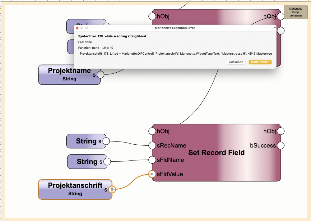
Within the marionette object I use the string node to enter text and write it to the record format, so that it is displayed in the symbol.
Works great as well. But only for singe line text.
When I try to enter multi line text like with the symbol itself I get the following error: EOL while scanning string literal (see image attached).
Any help appreciated,
kind regards
VvierA
-
Thank you very much Kevin and Tom for your kind help.
-
31 minutes ago, Kevin Allen said:
if you start with a topographic map and have the elevations that should be reasonably accurate.
I think once you have the topography there is a convert to command
I'm not sure if I understand this correctly. So I have a topographic map with contour lines. I move every contour line to the corresponding z-level.
But how do I convert this into a surface of some kind?
-
2 hours ago, Kevin Allen said:
I have extruded a number of organic shapes from topography. Then I have done (or not, as needed) a drape surface.
Thank you. That way I get pretty decent looking results. But I'm looking for a way to generate a terrain, that does not only look good, but represent the actual measurements of the reality accurately.
5 hours ago, markdd said:You should investigate the Loft Surface tool which will allow you to create a terrain using successive NURBS curves as contours in order to build up a solid shape.
The Subdivision tool is also a good tool for this kind of work and is a more interactive way of achieving a terrain. However, it has quite a steep
learning curve which it doesn’t sound like you need for now.
Yes, thank you. This looks promising. But I already tried it and it only got me some weird results. The surface didn't match the contour lines the way one should expect.
Maybe I did something wrong and try again.
-
Hello,
I am a user of the Spotlight version of VW but from time to time I need to generate a terrain surface by contour lines.
Is there a way to do this with basic 3d tools and operations as a way to mimic the particular functionality of the Architecture/ Landscape or Design Version?
Any help appreciated,
VVierA
-
Hello,
with VW 2022 there is a great new tool to assign textures to single surfaces.
I'd like to create a quantity report in a table that sums up all surface areas with certain textures.
The problem is: if I use object filter criteria to search for a certain texture the filter doesn't list singe surfaces but whole objects.
How can I list every single surface within an object?
Looking forward to any help
kind regards
VvierA
-
 1
1
-
-
Well there 'was' a solution until VW 2021 for the boomerang flyover with a trackpad or a mouse without middle mousebutton:
Just press space bar and then shift+c
or reassign the flyover to another key, for example to 'q'. And then press space bar and then q key.
Unfortunately this doesn't work in VW 2021 any more.
Any ideas or suggestions?
-
1
-
-
Can anybody help?
-
Hello there,
we use the Spotlight version that does not have the 'generate site' tool.
But very seldom - from time to time - we need to model a site.
Can anybody tell me how to do this with the generic 3d model tools?
Thank you
VvierA
-
Maybe I'm wrong, but I think there is one simple issue with screen plane and layer plane that causes most of the confusion.
And it's mostly a matter of conception or terminology.
We shouldn't see screen and layer plane as two sides of one medal.
Instead everything should be drawn on layer plane. And then there should be something like a checkbox like 'ignore perspective'.
If you check this checkbox, it causes the object to 'pop' off, and stick to the screen or to the plane of a viewport for annotation purposes or like an image prop.
-
@rowbear97
Yeah, I love it as well but I'd love it even more if it was usable along with class attributes override.
With this I could use it to highlight data or information in my regular drawings....
-
1
-
-
Hello,
the scenario is as follows:
Lets say you have some Design Layers named 'option 1, option 2, ... option 5'
You have a sheet layer for each option and you have a list an each sheet layer that adds up some quantities of each option.
The list works with a filter that searches for content on the layer it refers to, so the list for option 1 searches for elements on design layer 'option 1' and so forth.
Eventually you decide to discard option 1, and you delete the design layer option 1. You RENAME all the other design layers so that option 2 becomes option 1 and so forth.
The problem is: the filter in the list doesn't recognize the renaming. The result is, that every list on every sheet layer now shows the wrong data.
Maybe I got something wrong, but if not - I think this is quite dangerous...
Cheers
VvierA
-
Navigating through Layers via keyboard shortcuts may be a nice workaround in some situations.
-
I think the main problem here is that the toolboxes are cluttered and in total disorder.
Vectorworks urgently needs a revised user interface. It's a shame that users ask for a search tool to find the right tool. The aim should be to make it possible to work intuitively.
-
@markdd
Thank you, very interesting. I also think, that it can be a very powerful tool, but I fear, that a lot of users don't know that.
@JMR
Thank you JMR. Using it for internal quality control is another great thing. Of course in this case you won't miss the option to combine it parallel to class overrides. -
Oh thank you very much. I'll post it as soon as possible...
-
Hi there,
I was wondering which part of the VW community is using 'data visualization'.
I'm asking, because I opened a thread in the wishlist section of this forum and do not get any support for it.
Link to entry in the wishlist section
So maybe may 'wish' isn't relevant or only a very small part of the community is actually making use of 'data visualization'...
Looking forward hearing from you
VvierA
-
Hello,
the title of this question may sound a little strange, so I'll try to explain...
Let's say I have a network with 4 branches. Three of them depend on a choice so that depending on one of the three branches the network either draws a circle, a rectangle or a line.
These three branches are selected with three valve nodes.
The fourth branch is independent. I just displays some text. I want to feed it with either the string 'circle', 'rectangle' or 'line'.
Do do that, I'd like to define the string by attaching it to one of the three branches that emerge each from one of the valve nodes.
But how do I do this? Because the string node has only an output and not an input. I can only attach it directly to my text node.
As a workaround I could of course make 3 text nodes instead of just one and attach them to 3 valve nodes of their own which depend on the same choice from the 'beginning' of the node.
But this seems to me a little bit complicated, so maybe there is a more elegant way to define some input for later use?
Thanks again
VvierA
-
Ah I see... thanks.
And hopefully my last question for some time... if I'd like to write several record fields at once I will need a 'set record field' node for each entry.
But do I also need an 'attach existing record' node and 'parent PIO' for each entry or is it possible to connect several 'set record field' nodes to the same one 'attach existing record' node?

Can anybody recommend on how to set up a phyton scripting development environment in VW?
in Python Scripting
Posted
Sorry for asking once again... I use a Mac and I cannot find the Python interpreter that comes with the VW installation...?