


ReMatsu
-
Posts
38 -
Joined
-
Last visited
Content Type
Profiles
Forums
Events
Articles
Marionette
Store
Everything posted by ReMatsu
-
Mine works, try copying this:
-
Export to grandMA2 just to update the Universe/Adress
ReMatsu replied to Cristiano Alves's topic in Entertainment
I think this is a question better suited for the MA forum, but I guess the only way to do this is by doing a Partial Show Read. -
Hidden Line not rendering pen colors of lighting instruments
ReMatsu replied to ReMatsu's topic in Entertainment
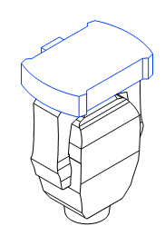
I tried to do that already. Funny thing is that, when the viewport is in preview (with the red border) the colors are fine, but when I hit update on the viewport some lines go back to black. Maybe it is a windows thing? Or something to do with my computer? In preview: After I hit update on the viewport: I already tried to change line thickness, changing line colors, changing the fills, checking and un checking all kinds of options like display planar objects, display2D fills, all the options in "Background render settings", and nothing seems to work.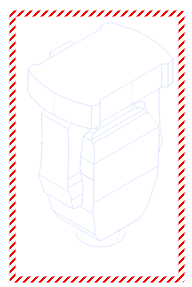
-
Hidden Line not rendering pen colors of lighting instruments
ReMatsu replied to ReMatsu's topic in Entertainment
Hi Mark! What did you do exactly? Mine looks like this: Is there some kind of configuration I have to change? I tried to mess with it in all kinds of ways, but I just couldn't figure it out. Also, are you on a Mac? I'm on windows 11, maybe is something on the windows version?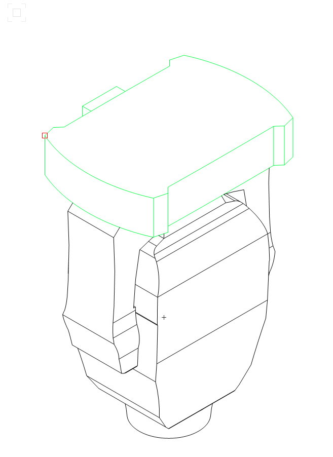
-
Hidden Line not rendering pen colors of lighting instruments
ReMatsu posted a topic in Entertainment
Hey guys, I'd like to color code my fixtures in a viewport with hidden line rendering but that's not working properly anymore. Some parts of the fixtures are colored, some are not. Can someone take a look at this, please? I attached a file with the issue. Thanks! HiddenLinesTest.vwx -
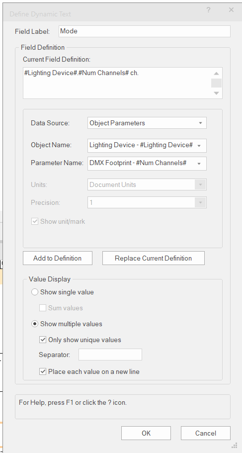
You're trying to pull data from the record format like the old symbol key tool. For this you have to choose "Lighting Device - #Lighting Device#" in the Object Name field, and "DMX Footprint - #Num Channels#" in the Parameter Name field. The graphic legend pulls data directly from the OIP so you have to change the data there, instead of changing it inside of the record format when editing the symbol. Hope it helps.
-
Label Legend auto spacing based on different fixture sizes
ReMatsu replied to Nathaniel.C's topic in Entertainment
It shouldn't break if you keep it inside the symbol boundaries, if the texts are outside of the boundaries they start to auto space. If the symbol is too small to keep everything inside, Data Tags is the best tool for you. (I think you should have a look at Data Tags anyway, it's awesome!) Ps. You can also try using the single label option, but I don't think they look very good. -
Label Legend auto spacing based on different fixture sizes
ReMatsu replied to Nathaniel.C's topic in Entertainment
That's happening because you are using center alignment on both, try using Right align for circuit name and Left align for circuit number. -
Export MVR - Export as 3DS does not export geometry
ReMatsu replied to ReMatsu's topic in Entertainment
Oh, I see, so I think that's the problem, instead o converting 1m to 1000mm it is just accepting 1m as 1mm, that's why the object geometry is "invisible". Thanks for the bug report! -
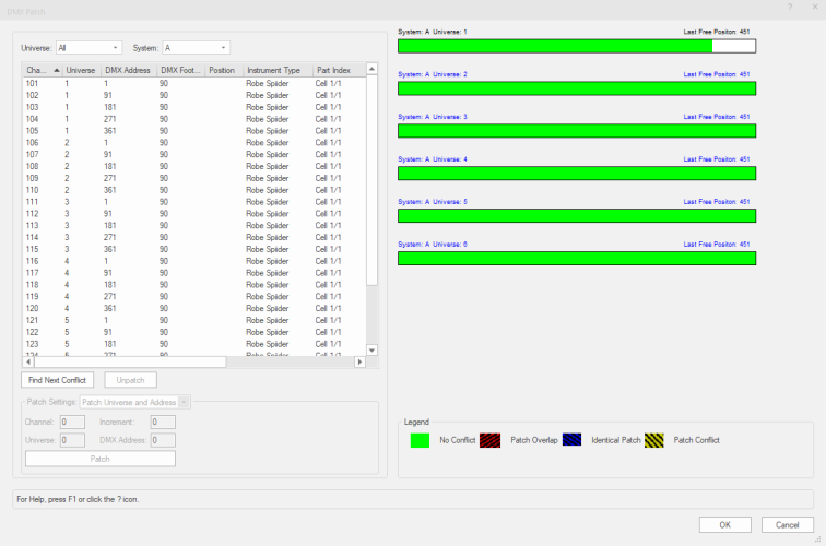
DMX Patch Window - Universe bars not working properly
ReMatsu replied to ReMatsu's topic in Entertainment
Cool! Thank you -
Export MVR - Export as 3DS does not export geometry
ReMatsu replied to ReMatsu's topic in Entertainment
When I was trying to recreate the problem, I discovered that if I keep the units in millimeters the export works, when I change to meters it does not. I think it is a scaling problem, the object is there but it's tiny. Here are the files. I'm having trouble uploading the MVR file, so I compacted it. It's in RAR. MVR_Export_Test_Win10_VW24_SP2.vwx MVR_Export_Test_Win10_VW24_SP2.rar -
Hey guys, I tried to export a simple cube (1mx1mx1m extrusion) to L8 as MVR, checked the "Use 3ds format" checkbox (L8 requires this), and imported into L8, the object was there but without geometry. I tried the same exact thing on 2023 and it worked. Can you check this out please? This is a very important step in my workflow. Thanks, Renato Matsubara
-
DMX Patch Window - Universe bars not working properly
ReMatsu replied to ReMatsu's topic in Entertainment
Sure Tom, thanks for looking into it. DMX_Patch_Test_Win10_VW24_SP2.vwx -
Is anybody else getting this? The universe bars always show full after the first universe. Or is it something I'm doing wrong?
-
Thank you!
-
Thanks for this work around! I think it`s a bug because it used to work on 22. Thanks again!
-
Sure, here it is. Thanks! StraightTrussToolTest.vwx
-
Hi vectorworks people, Can you guys check something for me, please? I can`t add distributed weight on a straight truss tool object, so it does not add weight when converting to hanging position. To recreate the problem: Open a a new blank document, add a straight truss tool object, and try to add distributed weight via OIP. It goes back to zero. Edit: I`m using VW2023 SP2 on windows 10. Thanks,
-
Go to: File > Document Settings > Spotlight Preferences. Then on the left side click on Lighting Device: Parameters, then find Universe/Address on the list, click on it and change the Default Value from / to .
-
Double click your symbols in the resource browser instead of dragging them. When you drag the symbol is added to the drawing as a normal symbol instead of a lighting device. You can also use the "lighting device tool" located on the lighting tools set.
-
You can still use the old one. Edit your workspace, Click the "Tools" tab, search for "Legacy" on the list and add Hoist(Legacy) to your tool set. That's what I did. 🙂
-
Problem with orientation of fixtures in top/plan vs. 3D
ReMatsu replied to cessna310's topic in Entertainment
Leave the 3D as desired then on the Object Info Palete, check the Custom Plan Rotation checkbox and enter the rotation for the Top/Plan portion of the symbol. -
Not sure if this will work, but try converting to a Generic Solid. Go to Modify > Convert > Convet to Generic Solids. This is what I do to solve this problem when exporting to MA 3D in 3ds.
-
Yes, in the resource manager. I think that`s odd too. But I think, it doesn't remove the geometry just doesn't recognize it, because if I edit the 2D or the 3D portion of the symbol, it's still there. To replicate this do the following: 1-Add a fixture to the drawing; 2-Rename it in the resource manager; 3-Refresh instruments; You'll see that symbol turned into a rectangle, both in 2D and 3D views. To fix it, use the replace instrument command and select the same symbol you've just renamed.
-
Did you rename the symbols? That happens to me whenever I rename them. To fix I have to replace the symbols, go to Spotlight>Replace Instruments.

