
bjoerka
-
Posts
453 -
Joined
-
Last visited
Content Type
Profiles
Forums
Events
Articles
Marionette
Store
Everything posted by bjoerka
-
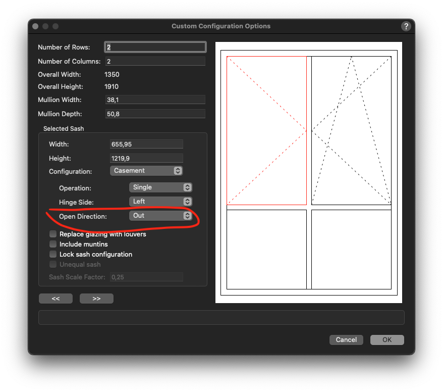
It seems, that when opening a file that is created with vwx23, the configuration of custom window settings are interpretated wrong. Single casements change their opening direction to the wrong side and have to be adjusted in the settings. Is that a known bug? Custom window in vwx23 same windows opened in vwx24 settings in the configuration dialog
-
Maybe take a look at the Anycubic Kobra 2. This is my second printer after the delta Flsun Q5 that i bought 2 years ago. The Kobra is much more accurate and much much faster than my previous one. It can print dimensions up to 9.8" in height and 8.7" in width and depth. Works perfect with PrusaSlicer on my Mac.
-
🙂 already changed that after wondering why the rectangle is that big .-))
-
Thank you Tom. Now it works!
-
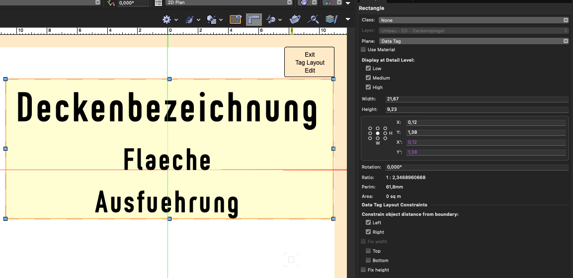
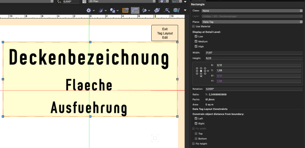
Hi Tom, that is what i already tried in several combinations, but after exiting the tag layout the rectangle isn´t shown... no matter what combinations i activate in the oip - the rectangle is never shown. but when i activate a data tag in the drawing there seems to something inside (left side)... screenshot of one of my attempts...
-
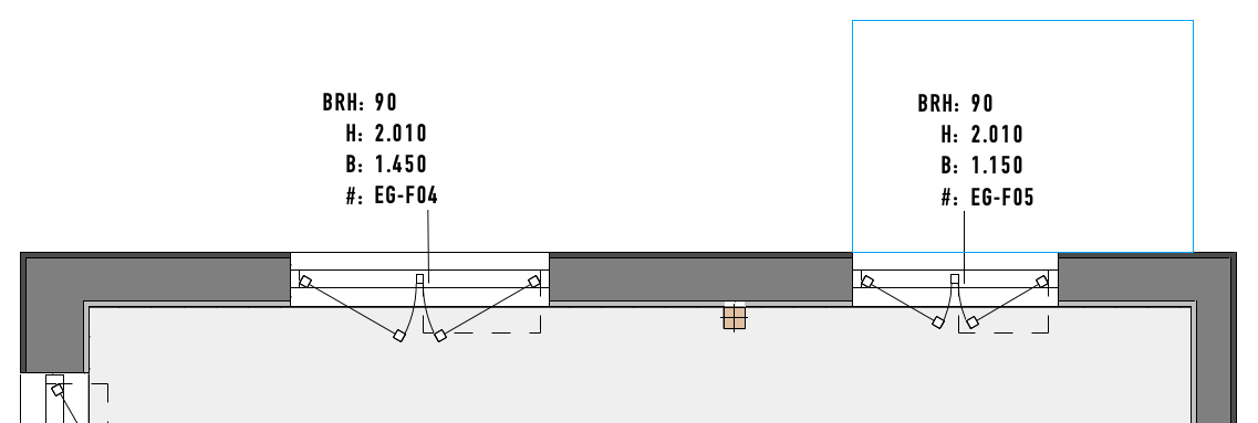
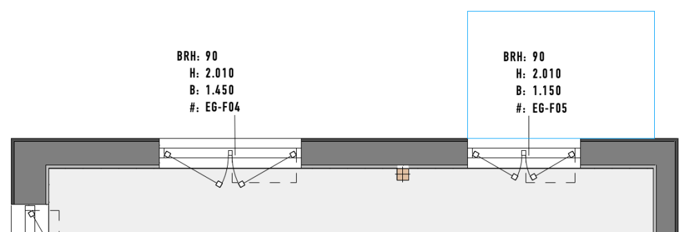
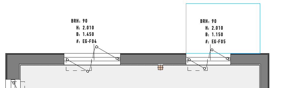
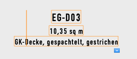
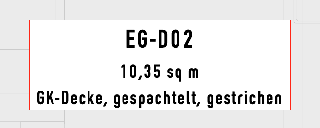
I am trying to add an object as background to a data tag that resizes automaticly to the bounding box of the entered data. Any advice how to apply a rectangle that will resize automatically? This ist how my data tag looks like... And this is how i want to look like...

-
Thank you Benson for explaining the way you did this. I will try to follow this on wendsday... we have a holiday on tuesday in germany and i will not be in the office on monday .-) But i think your idea is something that i can work with!
-
you are right. but i think the problem is to calculate these positions on a surface which is double curved. and the understanding of math, from my side, is as far in distance as Mos Eisley is....
-
I think this is where Surface Array on a sphere is getting to it´s limit because auf the uv´s that are getting closer to each other as much as the top and lowest point of the sphere is reached. sorry but i can´t explain it better. it´s a bit like lattitude and longitude on our earth .-)
-
corrupted preferences .-) sometimes it helps, when strange things happen, to run the vectorworks updater and choose under advanced section the repair option...
-
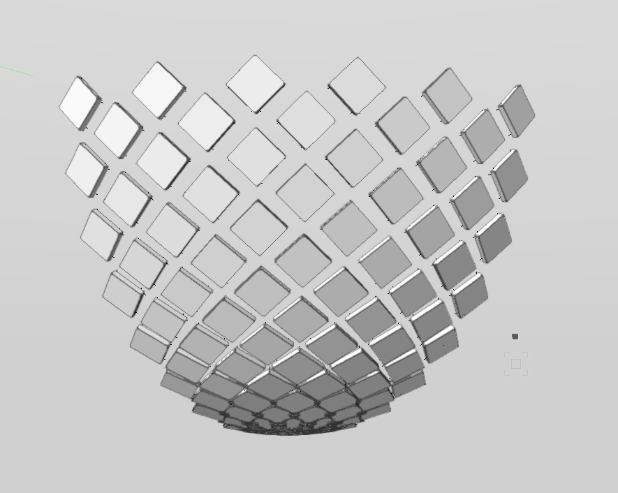
ii gave that a try, to be seen in the second screenshot, but at the lower end, the gaps are closed and the tiles are overlapping. so, i want to find a solution where i can control the gaps from one to another element in a defined distance. surface array doesn´t do that for me...
-
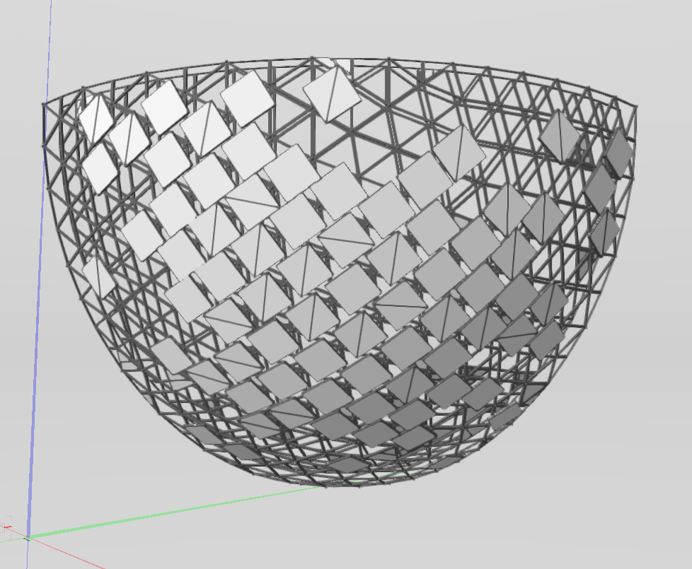
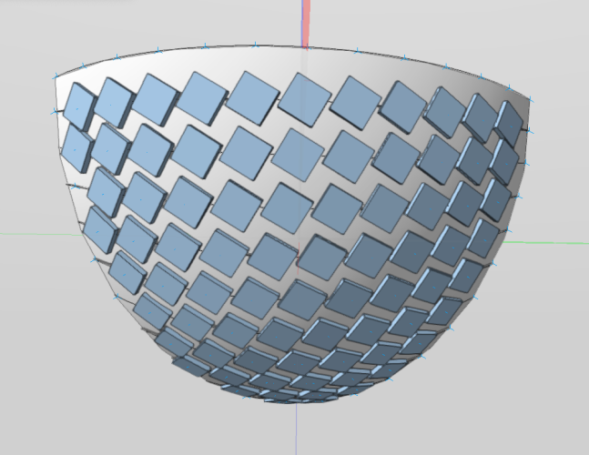
I have a task of which i have no idea how to model it in a comfortable and better adjustable way. I am trying to distribute a 3d symbol on a segment of a sphere. The target is to get a constant structure, similar like it is shown in the first image attached. This was modeled in Maya or C4d by one of our collegues. Now it is my task to bring this to a better stage to make a real planning to this. My first attempt was to use the surface array command, but this leads into unregular gaps between the extruded tiles. (second image attached) As i didn´t find any other tool i modeled it in steps. Slicing the 8th of a sphere, extruded the outlines to nurbs curves, placed 3d loci on that curve and finally placed the 3d symbol according to the nurbs curve normal and rotated them to the center of the 8th of the sphere. Final result - not what i expected .-) Is this, expcept for a Marionette, impossible to get a better and more flexible workflow? thanks! bjoern 1st image: maya c4d design 2nd image - surface array 3d image - modeled manually
-
Very nice! Thank you!
-

Push Pull tool and/or 3D polygon does not work
bjoerka replied to MGuilfoile's question in Troubleshooting
You can turn on the "Snap to working plane" in the snapping tools. Or you can define a custom working plane and then activate "Look at working plane" Hope that is what you are looking for... -
can you share the dwg or send it per pm? i can try what my vwx will do
-
Push Pull tool and/or 3D polygon does not work
bjoerka replied to MGuilfoile's question in Troubleshooting
PPT works for sure with 3d polys. Maybe it´s related to the SP5. Try uodating to the latest SP7 as zoomer wrote. -
"Show other objects while in edit mode" does not work
bjoerka replied to MGuilfoile's question in Troubleshooting
Sometimes there are corrupted files in the vectorworks program folder. Open the vectorworks updater, on the right hand click on advanced options and choose the repair command. In most cases this helps with strange thins like tools or menue command that are not available. -
try pressing "command-k" and the dialog box will appear. or go to Modify - Convert - 1st entry... Convert to group
-
Collaborating in real time, same file
bjoerka replied to oliver.williams's question in Troubleshooting
Yes. I think it always depends where your co-workers are located. If everybody works in one location then the project sharing server on a local machine in your network is for shure the faster option. Using cloud storage system has always lead to a kind of delay when someone has committed their changes until you´ll be notified inside vectorworks that changes have been made to the project. -
I sometimes have the same problem. But it always depends how the modeling in Rhino is done. When inside Rhino most geometry is built with nurbssurfaces dwg will lack in transporting everything correctly. Did you try to export and import stl or iges? That works mostly for me...
-
Collaborating in real time, same file
bjoerka replied to oliver.williams's question in Troubleshooting
I think what you are looking for is the Project Sharing option. There it is possible to define a vectorworks file as a project sharing file. After opening that file on a desktop computer, the project file will be converted into a project sharing working file and several users can work on their own working file and commit their changes to the file on the server. -
You are right. I tried to import it as revit file not as Site Model. I even didn´t know what´s inside .-) The files are created with the following version: Autodesk Revit 2021.1.7
-
Hi Juan, i just sent you a message containing the file.
-
I have a small rvt file to import (30mb) and vwx24 and 23 crashes after the dialog which shows the revit structure. Is that a known problem?
-
Hi Kristian, thank you very much! Did this change from version 2022 to 2023? I´ll apply this to my file!