


bjoerka
-
Posts
452 -
Joined
-
Last visited
Content Type
Profiles
Forums
Events
Articles
Marionette
Store
Posts posted by bjoerka
-
-
I just looked in the settings for CC...
There the settings for Circuit label Offset were set to 1 by 1.
I changed these and then the device builder draws the spacing for the connectors in the right way.
I formerly changed only the snapping grid directly in the snapping settings...
A little bit confusing but now it works .-)
-
@Nikolay Zhelyazkov i send you the file directly per pm.
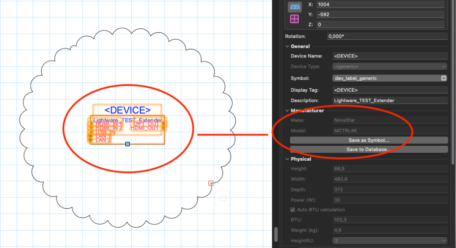
Another thing that i came across is a misfunction in the Make/Model dialog.
The "Lightware_Test_Extender" was created making a new Model. In the upcoming dialog i have chosen Lightware as manufacturer and category set to "Extender Video".
After the device is drawn in the layout, in the OIP Make is stated to "NovaStar" and Model "MCTCTTL4K"
This is not what it is supposed to generate, right?
See the screenshot.
-
I´ll look deeper into that tomorrow.
These windows have been created in vw23 and maybe it´s an issue when these are translated into the current version.
BTW how do i submit a bug report?
-
Yes Tom. These are my settings.
-
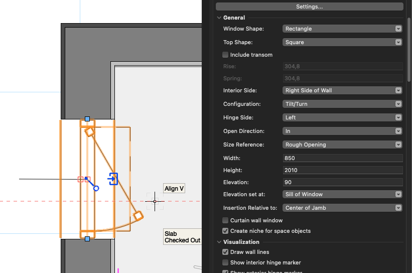
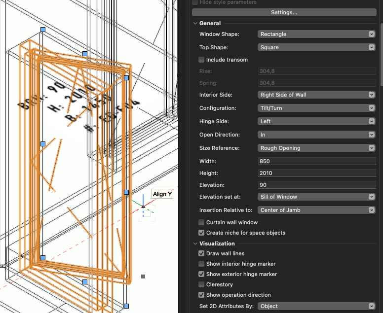
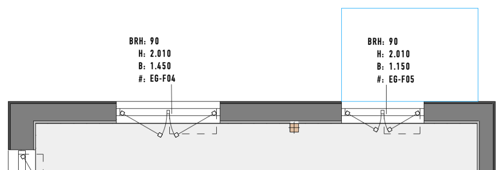
I have a window which always shows the wrong hinge markers for exterior and interior display.
When the hinge side is set to left i get was is shown in the screenshots.
When the hinge side is set to right the display of the hinge markers in 3d are correct?
Do is have some wrong settings or is this a problem in vw24?
-
 1
1
-
-
Thanks for the hint.
I checked the CC template and there, for metric templates, the defaults are 4*4 and 16*16.
But these are the same as in my template.
So i changed it to in my template to 8*8 and 16*16 and then the spacings looks much better!
-
I am new to CC. Formerly used to draw my schematics and rack layouts with Stardraw .-)
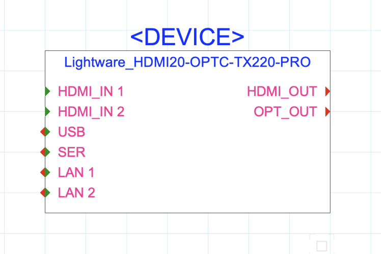
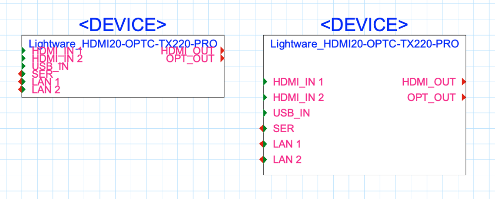
I am trying to generate new devices with the device builder.
Here it is an extender for video.
Are there any settings i don´t know to get the connectors inside a device distributed with more space?
I can change the layout when the device is placed in the drawing, but when i place another instance with the device builder the layout is as narrow as it was inside the device builder...
Left image is what is generated by the device builder, right image what i like to have it look like
-
OK. Thanks Nikolay.
The this is a wish to generate user categories for this section.
I edited the CableTypes.txt file that´s inside the program folder .-)
I´ll make a copy of that in case it get´s overwritten with the next servicepack.
-
1
-
-
Usually means - there is no way to sort my cabletypes in categories?
Forgot to say - im in vwx24
-
Did you check that your class the lights are in, is turned on in the viewport?
-
On 5/18/2020 at 3:51 PM, Conrad Preen said:
You can add Signal and Connector types. Have a look in your user folder under Plug-ins/connectCAD_Data and you'll find the files SignalTypes.txt. and ConnectorTypes.txt. Questions:
Is this method also possible to add cable types?
When adding different additional cable types in the settings dialog, i can´t assign them to an existing type like Audio/ Video etc.
-
hi tom, i had this too after updating to sp1.
i opened the updater again, ran the repair procedure and from then this never occured.
-
1
-
-
When i click the On section in the visualization palette often or maybe to fast (as interpreted as a double-click) the appropiate light get´s activated and is centered on the screen.
And after that happens, the light is switched on but the checkmark in the palette shows off.
Seems to be not working properly.
vwx24 sp1
-
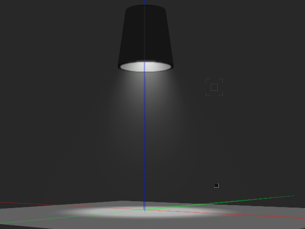
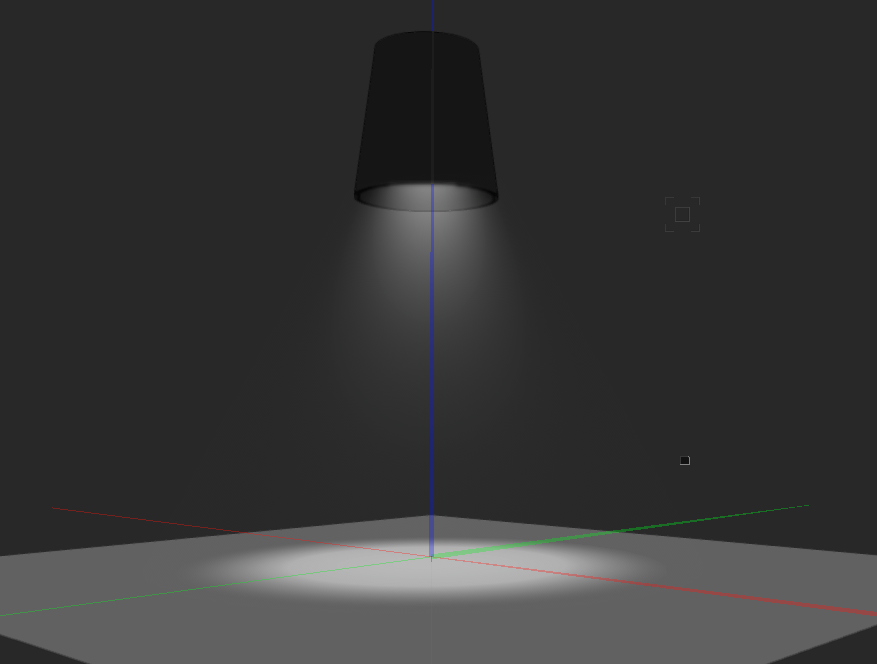
Another idea is to apply a glowing texture to the inside of the lamp .-)
-
2
-
-
Try to apply a RW Background to the scene which has lLit Fog enabled.
Same Lit Fog has to be enabled in the light itself...
Maybe this will give the effect that you want.
-
i think this is related to the setting to show the shim gap or not to show.
Settings are in the Jamb section.
-
1
-
-
yes correct. but the main problem is that most of these elements are part of symbols and so someone has to manually go through all symbols and edit these.
and inside the symbol it is not possible to change these elements from screen plane to symbol definition. it always swaps back to screen plane...
-
1
-
-
In the document preferences under the first option "Display" there is a setting "Ignore layers with different scale"
Is that what you are looking for?
-
as we have a lot of project files and employees that start new projects not from scratch, i was searching for a similar topic like this one.
Pat´s script works perfect, but i have some drawings where lines and polygons can´t be shifted to layer or symbol workingplane. They always stay in screen plane.
Is there any way to "kill" this screen plane feature and push element to layer plane?
-
Hm. But as in vwx23 there was no option to tell a single sash in which direction it has to opened, every sash, imo, has to be drawn in the same direction- to the inside of the room.
And the windows that i inserted in vwx23 are unstyled .-)
-
Yes Tom, but i still think this is a conversion problem from vwx23 to vwx 24 .-)
-
If you are looking for models from suppliers for BIM related things, then you can find many in native vwx on www.bimobject.com
-
1
-
-
Yes. I think this option is new in vwx24. And yes when i flip the window with the new controls it doesn´t change the opening direction. Flipping the window with the OIP sometimes does not do anything. Seems to be overridden by the new controls inside the window.
In vwx23 there was no option to define the opening for a single sash, or did i miss something?
-
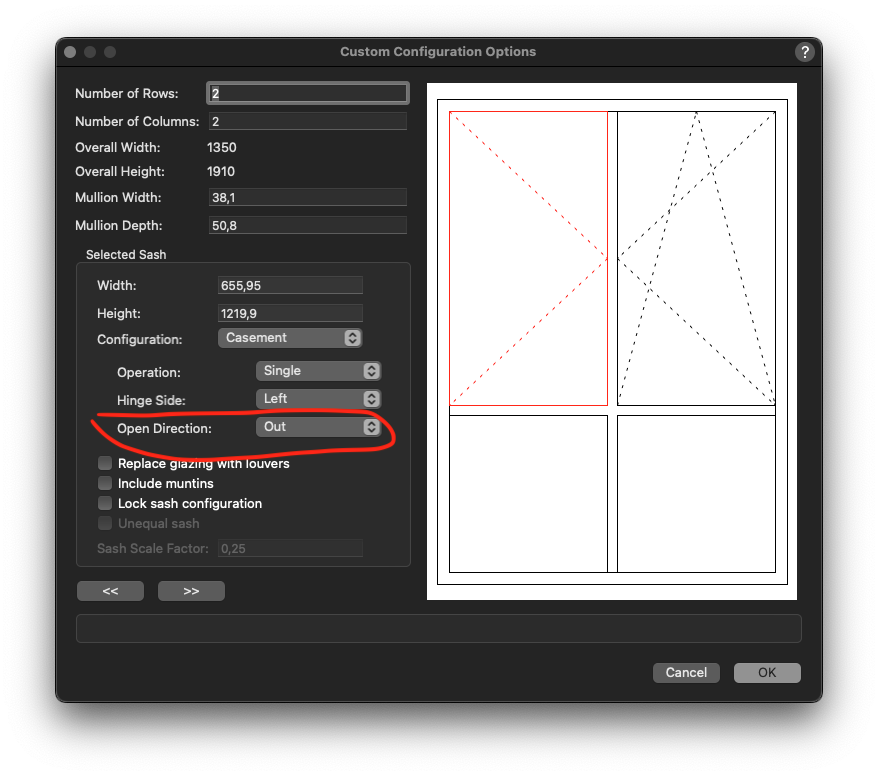
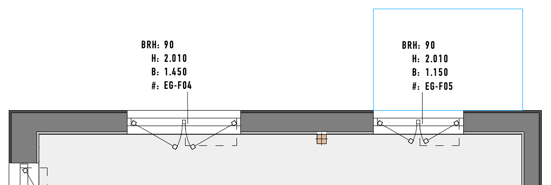
It seems, that when opening a file that is created with vwx23, the configuration of custom window settings are interpretated wrong.
Single casements change their opening direction to the wrong side and have to be adjusted in the settings.
Is that a known bug?
Custom window in vwx23
same windows opened in vwx24
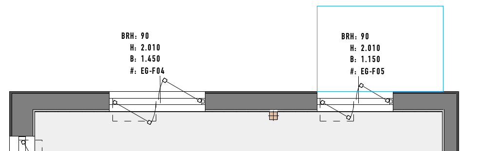
settings in the configuration dialog


Why does Vectorworks Break Moving Grouped Objets
in Troubleshooting
Posted
For me it is only the bounding box that visualizes the group.
When deselecting the group and select again, the group is ok.
Seems to be a redraw issue.
Somebody reported this too on lighting devices, i think.