


Ed Wachter
-
Posts
198 -
Joined
-
Last visited
Content Type
Profiles
Forums
Events
Articles
Marionette
Store
Everything posted by Ed Wachter
-
3DConnexions Driver Upgrade problems w/ Space Navigator
Ed Wachter replied to Ed Wachter's topic in General Discussion
Never mind. I was able to find the older driver (10.7.0). I reinstalled that and everything is working well again. Ed -
Today I installed the driver version 10.8.3 for MacOS. My Space Navigator still works but I can't control the speed and can't get the buttons to invoke a keystroke command. Please let me know if you're having similar problems or have ideas. We've been using the Space Navigators for close to a decade. Each driver update seems to be difficult. I love the product once it's working though. Thanks, Ed
-
Thanks Juan. Ed
-
Where do I find Scott's videos? Thanks, Ed
-
Hi all, I am exporting DWG floor plans to a structural engineer who is using "Autocad 2019 3D Map". Some doors and windows are changing width (getting wider) in his software, so that they extend beyond the ends of walls. He sent us a PDF, a portion of which is attached. I've been exporting DWGs to consultants for at least a decade without running into this. Any thoughts? Are there DWG export settings that might prevent this? Thanks, Ed Screen Shot 2024-01-25 at 5.42.23 PM.pdf
-
I think I'm beginning to understand this. It seems that the snaps don't work when I have a lot of 3D geometry displayed. It makes sense that the computer would not snap reliably when there are many edges, surfaces and points to possibly snap to. I am getting better results when I display only one layer or one class, or orient the view so there is no geometry behind the edge I want to snap to. Ed
-
Hardscape Objects disappear while editing surface modifiers
Ed Wachter replied to Ed Wachter's topic in Architecture
Thanks. The next time I use Aligned Hardscapes I will keep all of these suggestions in mind. Ed -
I’ve been using Vectorworks, in 3D, daily for over a decade and I still don’t understand when snaps are going to work, and they only work about half of the times I want them to. I often have to align objects in plan view and then guess at distances in the Z direction (because the Tape Measure, or 3D loci, won’t snap to the objects in 3D). Then I move objects vertically by trial and error until I get them close enough. I also frequently struggle using the Move command in 3D; I can snap to some edges but not others. I’m currently looking at extrudes where I can snap to the top edges but not the bottom. I think I understand how the snaps are supposed to work; I don’t have any problems in 2D. I’m particularly interested in using snaps (in 3D) with the Tape Measure, 3D loci and the Move command. Are there circumstances in 3D when they don’t work? Is it possible that after a model gets crowded with a lot of geometry, the snaps get confused? It often seems like the curser is snapping to objects I can't see. I'd appreciate any thoughts! Ed
-
Building Geometry Disappeared from Section Viewports
Ed Wachter replied to Ed Wachter's topic in Architecture
@Pat Stanford, That thought also occurred to me and I deleted the crop in one VP and zoomed out looking for the model, but did not see anything. After reading your message I did the same in other VPs and found the model. Somehow I fooled myself. I don't know how. Could I cause this problem if I accidentally moved the internal origin? Or only by moving the model? Thanks, Ed -
Suddenly, all the section VPs in a VW2021 file are not showing any of my building geometry. All of my Anno drafting and notes are still there. I can select the VPs. They're still called Section Viewport in the OIP. The design layers layers and classes are still turned on in the VPs. But updating does not show any hint of the building. I've been working with this file for a few years with out any problems. Have you ever experienced this? Any thoughts on how to fix the VPs? For now, I'm recreating the VPs, unless someone has any other suggestions. Thanks, Ed
-
Thanks @Jeff Prince. Let's wait for now. I don't yet need a new texture. I've been expecting the project designer to ask for another option, but so far the designer and the client are happy with the panels stacked. If we do end up needing a staggered version, I can make a new image, or get help from co-workers with have more Photoshop experience. For now, I just wanted to know whether I would create a new image or start from scratch with the brick shaders. I expect a new image to be easy. The Shaders however look like a time-consuming process of trial and error. In cases like this, where we know what siding product we want, and the manufacturer provides a good image, I think it's easiest to start with their image. Thanks, Ed
-
@Jeff Prince I think I misunderstood your comment about using the brick shaders. I thought you meant that I could keep using the same image but use the various shaders to get that image to repeat in a running bond. But it appears that I must either choose my image, or go down a completely different path of using the shaders to recreate the look of my image. Is that correct? Let me know if I'm missing something. My current thinking is that it's easier to make a new image that includes two courses of this particular siding product, with one course staggered. Since the manufacturer has provided a nice image, it seems easier to get that look by using that image. Thanks all. Ed
-
OK. There's two votes for creating a new image that includes multiple panels and @Jeff Prince suggesting that the built-in brick shaders can create a staggered pattern using the image of a single panel. I will try the brick shader controls first; I'm guessing that any new image that contains a half panel will show an unwanted seam line where the half panel repeats. I'll post another message after I explore this further. Thanks, Ed
-
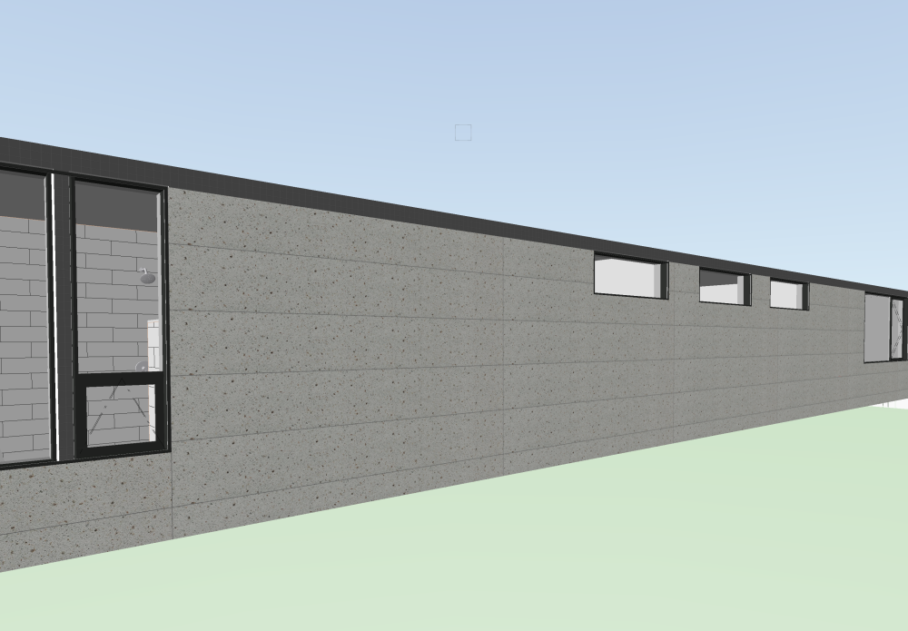
The texture shown on the wall in this screen shot is made from a JPEG image of one siding panel (18" x 10'). The image repeats in a stacked fashion as shown. How do I get a running bond or get the vertical joints to be staggered? Can I use this image of one panel, or do I need to make a new image that includes multiple rows and panels that are staggered? Thanks, Ed
-
Yes, I'll now use the extract surface method for siding also. Thanks again. Ed
-
Thanks @Tom W.. When I opened the file this morning the report made more sense (I don't know what changed). The Net and Gross areas were either the same (no windows), or the Net areas were smaller, apparently by an amount equal to the window area. And yes, the thickness now makes sense as expressed in fractions of a foot. Thanks for your help. I'll look for other reasons to use the Create Report command. Regarding the area take-offs for for the energy load worksheet, I might still prefer the Extract Surface approach. Once those polygons were created I needed to reshape a couple of them to follow the heated envelope in a way that the walls do not, e.g. where a wall concealed a scissors truss. Thanks, Ed
-
And it's fast too! It only took several minutes to get all the wall areas. EW
-
@E|FA Thanks Allan! It seems like you're always a couples steps ahead of me. I should just start sending my questions directly to you. That is a nice method because it omits the window areas. I've got another week before the permit submittal. Maybe this thread will provide some other direction. Otherwise, I'll do what you did. Thanks, Ed
-
I'm hoping to have VW tell me the areas of exterior walls so I can enter the info into an Excel heating system sizing worksheet. I am currently using the Create Report command and choosing Preformatted Report, and then choosing Wall Area. Attached is a screen shot of what I'm seeing and why I'm confused. What units are being reported? The numbers shown do not make sense for either square inches or square feet. Is this a good approach for finding areas of the exterior face of walls? My current project is in VW2022. Thanks, Ed Wall Area Report.pdf
-
Thank you all! That worked. And even though two of you warned me about the 'Replace Current Definition' button, I forgot to use it the first time. But I'm glad you warned me. I hope you have a great weekend! Ed
-
Thanks @E|FA. I think Tom gave me all the info I needed. I just need to follow through on editing steps that are unfamiliar to me. When all else fails, I'll watch those videos. Ed
-
Thank you @Matt Panzer and @Tom W.. The tag Matt provided is easy to use, but it's not the graphic format and the exact data that I want to display. I think I can edit graphic layout using the "Edit Tag Layout". However I want the wall elevation referenced from the layer elevation of a different layer than the walls are on. I like Tom's approach because I think duplicating and editing my existing tag is the easiest path. But where do I find the tag field definition? Ed
-
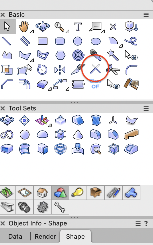
If you haven't already tried it, I would at least try using the Connect/Combine Tool in the Basic tool pallet. For years I thought that tool was only joining lines, so I was delightfully surprised to learn that it joins roof faces. But as @@cberg pointed out, it doesn't always work. It seems to work only in the simplest cases. Your case might be that simple. Ed
-
I am using data tags in VW2023 for calling out top-of-wall elevations. How do I call out the bottom-of-wall elevations? Do I somehow use the same tags? Is there a dedicated bottom-of-wall tag? Do I have to create one? Thanks, Ed
-
Slab drainage tool - Unable to places drains where I want them
Ed Wachter replied to Ed Wachter's topic in Architecture
@M5d Thanks. These seem like great solutions for me. Ed


