tsw
-
Posts
56 -
Joined
-
Last visited
Content Type
Profiles
Forums
Events
Articles
Marionette
Store
Everything posted by tsw
-
Dassault offers a free version of DraftSight—definitely useful for cleaning up DWGs prior to import.
-
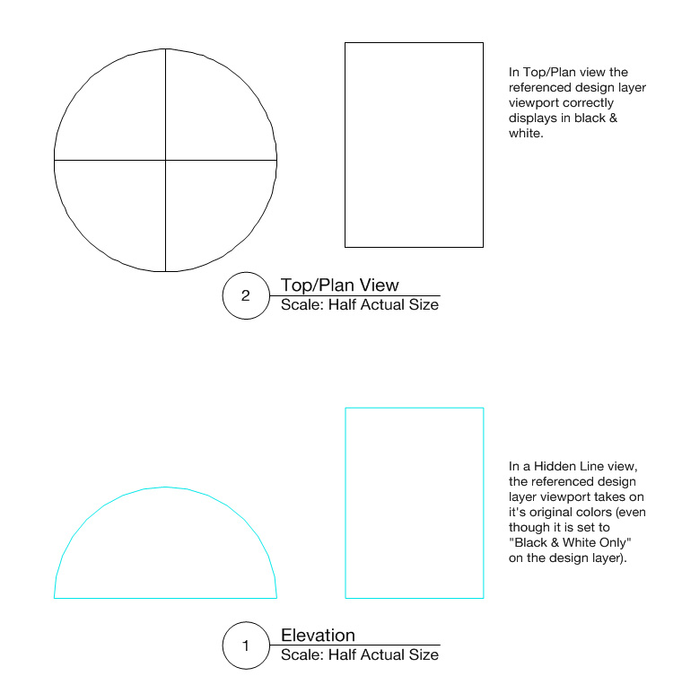
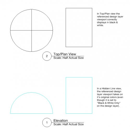
In Vectorworks 2018 (Windows 7 64-bit), if you select "Black and White Only" under Advanced Properties of a referenced Design Layer Viewport then create a Sheet Layer Viewport, Hidden Line mode will render using the original colors of the referenced file. This is different than Vectorworks 2017 and (I'm assuming) a bug. Is this a known issue? Any workarounds? I don't want to check "Black and White Only" on my Sheet Layer VP since I have other objects and callouts I'd like to show in grayscale. See attached file for an example. BW Viewport Example Files.zip
-
Very Basic - Possible to do a 'solid fill' section-cut through SketchUp import.
tsw replied to NICKY WAYLO's question in Troubleshooting
One other thing you can try (but it's very dependent on how the original Sketchup model was made and how complex it is): Select your imported Sketchup mesh. Modify > Convert > Convert to NURBs. Ungroup the resulting group of NURBS surfaces. Model > 3D Power Pack > Stitch and Trim Surfaces. If all goes well, you should end up with a Generic Solid object that will appear in section correctly. -
Looks like VW2018 Service Pack 2 fixed it. Thanks!
-
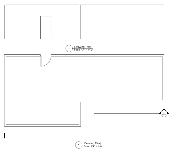
Broken section line viewports don't seem to be rendering correctly in Vectorworks 2018 SP1. It appears to be cutting a section along the initial line instead of following the broken line. See example below. If I export this file to VW2017, it renders correctly. Is this a known issue with VW2018? section test.vwx
-
Not sure on the first, but for the second question: I think you have to open those resource files individually which will convert them to version 2018. After resaving as VW2018 files you should be able to add them to your Resource Browser.
-
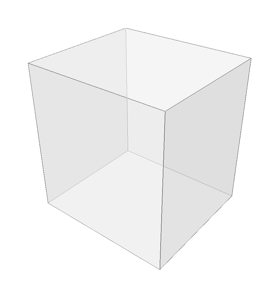
Has anyone tried playing with the new "Shadow Catcher" shader in VW2018? Looks like it's made for this type of situation. Attached is a test file and the resultant PNG with transparency. One advantage is that you could deform your shadow catcher plane or apply the texture to a site model. This would make the shadows appear to be hitting an irregular surface, which could look more realistic in the final composite. Edit: I tried applying a displacement map to the shadow catcher plane, thinking it would be a quick way to simulate shadows cast on a rough surface like the beach in barkest's file, but unfortunately once you make a texture use Shadow Catcher, it greys everything else out. (You can't have both a Shadow Catcher in the Transparency channel and a displacement map in the Bump channel.) Still a pretty cool new feature though! Shadow Catcher Test.vwx

-
Dashed line on 3D plane shown as full line in section viewport
tsw replied to Bertf's topic in Architecture
Thanks for taking a look at the file and confirming it happens on your machine too. Good to know it's not something specific to my set up! I submitted the bug report with a link to this thread. -
Dashed line on 3D plane shown as full line in section viewport
tsw replied to Bertf's topic in Architecture
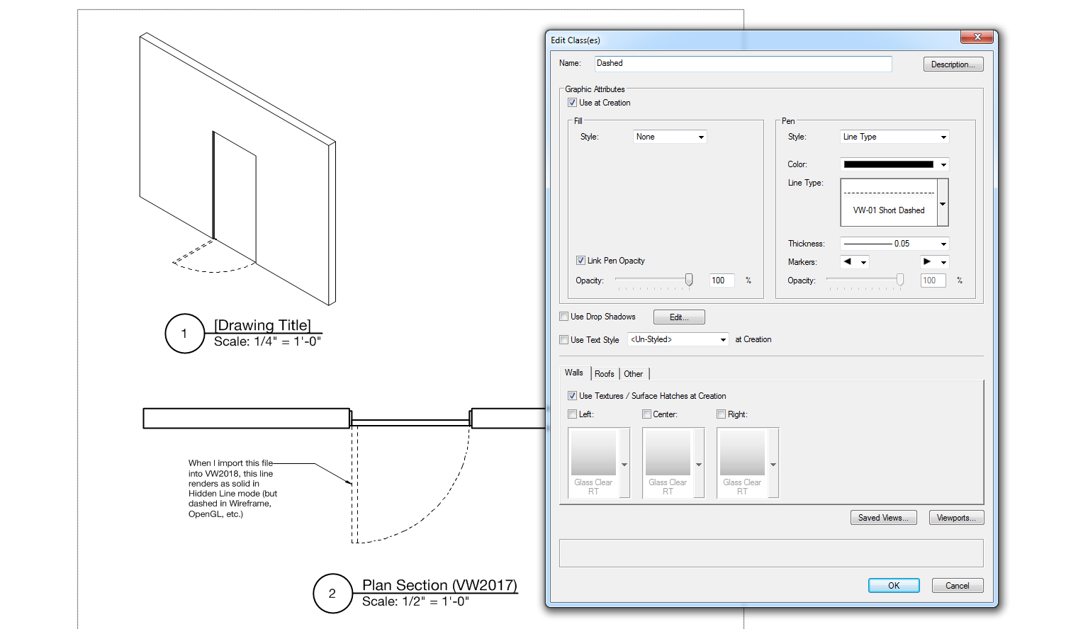
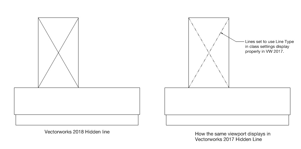
Here's another quick test file. I can get the look Bertf is going for in VW2017, but when I open the same file in 2018, the previously dashed line renders solid. Is this happening for you too? Screenshot of how the Hidden Line viewport looks in 2017 (vwx file also included): dashed line test v2017.vwx
-
Dashed line on 3D plane shown as full line in section viewport
tsw replied to Bertf's topic in Architecture
I've been having the same problem in Vectorworks 2018. In VW2017, I could make objects in a section/hidden line viewport display dashed by making sure they were set to use class attributes. However, this no longer seems to work in VW2018. See this thread for an example: -
In addition to the suggestions in the thread Andy linked, you could try applying a transparent texture to your object then duplicating it in place and removing its fill. It will then display as a wireframe in OpenGL (albeit without anti-aliasing, so the lines are a little jagged). It's a bit of a workaround (and makes further edits a little tedious), but it kind of achieves what you're going for. Here's what it looks like in a rendered viewport:
-
Sketchup 3D Warehouse is a good resource for free 3D models (and they're easily importable into Vectorworks). The quality can vary quite a bit, but there are a lot of common objects (some even provided by manufacturers). https://3dwarehouse.sketchup.com/search.html?backendClass=both&q=radial arm saw
-
If you add a crop object to your viewport that extends above the roof line I think it should work as you've described without the need for a background object.
- 1 reply
-
- 1
-

-
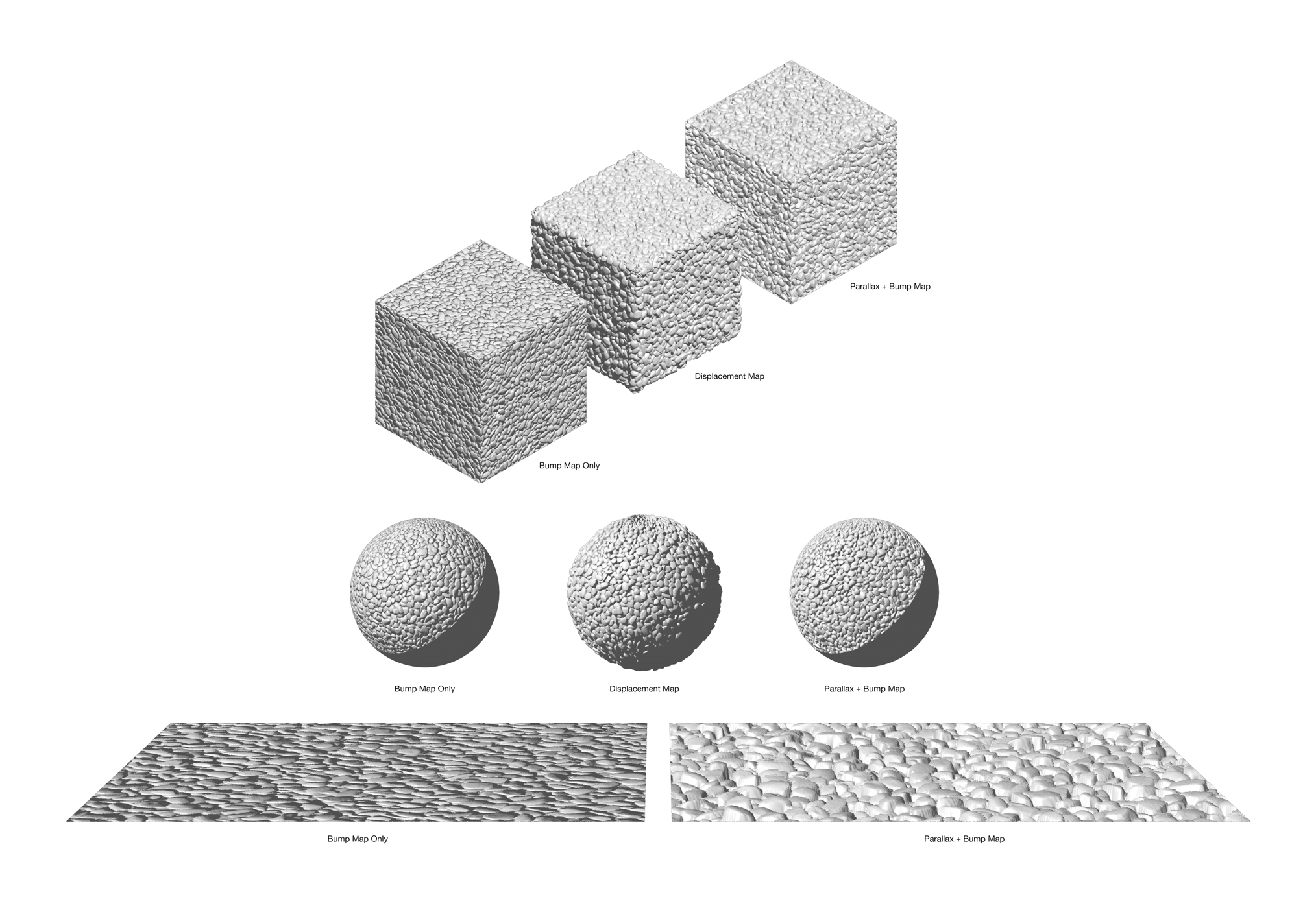
I've been playing around a bit with parallax mapping too. My understanding is that the intent is to simulate displacement mapping, but without creating real geometry (thus avoiding the increase in render times). Here's an example image and VWX file that uses a PNG for the bump/parallax shader. Note that I think you need to also have something greater than zero in Bump Strength for the effect to show. The biggest advantage is that parallax mapping can occlude itself vs. plain bump mapping which cannot. If you look closely at the examples you'll notice the pebbles in front are covering those in the back, while the plain bump map looks "pasted" on the surface. The difference is even more pronounced at a steeper view angle (bottom image). What's odd to me is that shadows don't appear to be effected by parallax mapping, so it looks a little artificially flat on the sphere example. I'm not sure if that's a limitation of parallax mapping. (It would be really cool if it was possible to turn on Self-Shadowing with parallax mapping!) Parallax.vwx

-
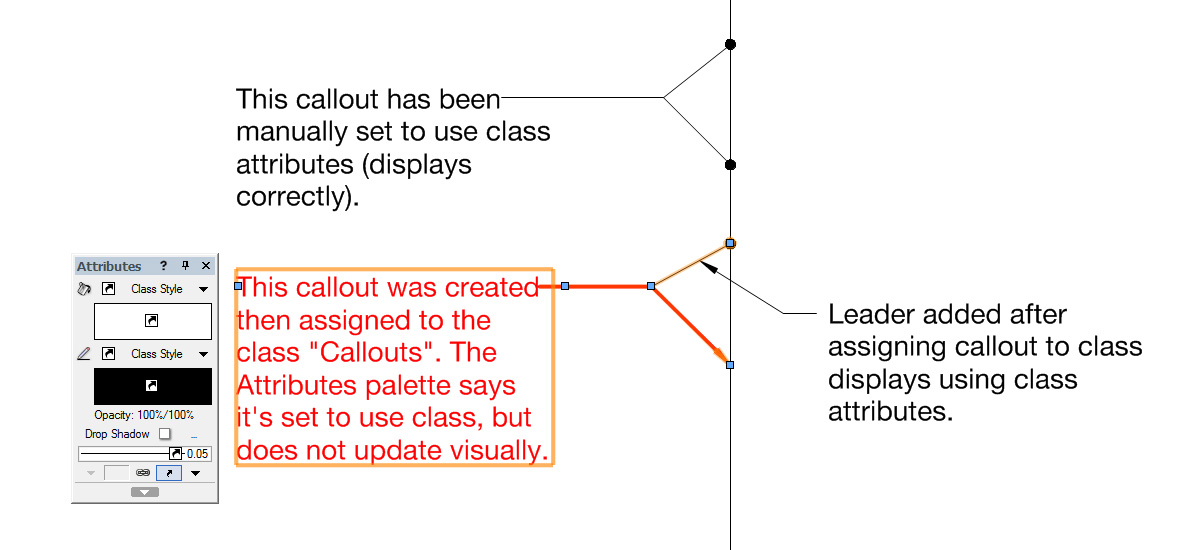
Yes, I've run into a similar problem as well (VW2018 Win 7 64-bit). See attached file. Callouts don't seem to be using the correct class attributes, even though the Attributes palette shows it's set to use class. If I manually set the object to use class it works, but not if I simply assign the callout to the custom class. As you can see in the screenshot below, the Attributes palette even shows the correct class color (black), but the callout remains its original color (red). I haven't noticed this bug with any other object type. Callout test.vwx
-
I ran into a somewhat similar challenge a while ago and received some great suggestions. Take a look at the thread below:
-
I'm running into problems getting line types to display in hidden line viewports in Vectorworks 2018 (Windows 7 64-bit). In VW2017, if I setup a class to use a line type (dashed, dotted, etc.) it would display that way in hidden line viewports. In VW2018, objects inherit the correct line weight/color from the class, but not the line type. Attached example files in v2017 and v2018. Anyone know of a workaround, or is this a bug in v2018? Thanks for suggestions! Line Type test v2017.vwx Line Type test v2018.vwx
-
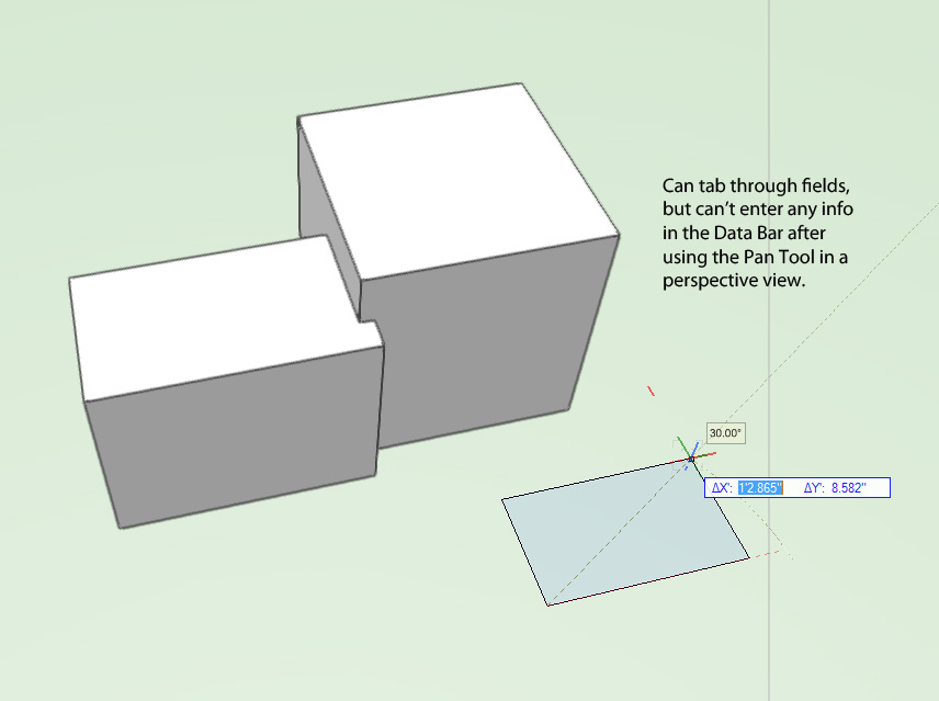
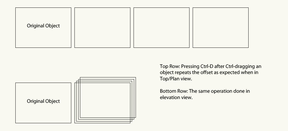
I recently installed Vectorworks 2018 on a Windows 7 64-bit system and came across a couple issues. I'm curious if anyone is experiencing similar issues, or if maybe something got messed up during installation or while migrating my preferences from v2017: I lose the ability to enter information in the Data Bar after using the Pan tool or Walkthrough tool in perspective view. Restarting or reloading the file corrects this (until the next time I use the Pan tool in perspective view). If I duplicate an object by holding Control while dragging it, pressing Ctrl-D should repeat the offset. However, this only seems to be working in Top/Plan view. When I try it in a 3D or elevation view, it offsets the object by the default amount instead of the distance/angle I previously specified.
-
I found out what was causing the problem! When I imported a DWG for this project, I used the option "Center first import". Importing this particular DWG had the side effect of moving the User Origin really far from the Internal Origin (76,215 feet). Once I reset the User Origin, everything seems to be behaving as expected. Anyway, I hope that helps in case anyone else encounters a similar problem.

-
Good to know it's not just me! I haven't had this happen until recently. I installed Service Pack 4 a few days ago, but I don't have any way of knowing if that introduced the problem, or if I've just been lucky up until now. Things I've tried so far: Resetting Vectorworks preferences per this article: Link Exporting to VW2016 and seeing if the problem persists in an older version of the file (it does).
-
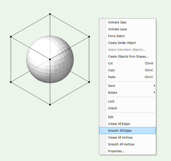
If you have just a few edges/points you want to crease, you could right click while in edit mode and select "Smooth All Edges" and "Smooth All Vertices" to ensure the entire subdivision is smoothed. Then go back in and crease just the edges/points you want creased. It doesn't directly address your issue, but it might be a workaround if it's not an overly complicated subdivision.
-
Hello, This is a weird problem I haven't had before. For some reason in the attached file, I can't draw on the faces of the lighter extrude when active plane is set to Automatic. I also can't use the Set Working Plane tool on the faces of the extrude. Selection also behaves oddly—I can only select the object by clicking points/edges of the extrude, not the faces. It's like Vectorworks doesn't "see" the faces. This happens with any new geometry I create with any of the rectangle/circle/polyline drawing tools in this file. If I paste in an extrude made in clean file (the darker one in the attached file), it works as expected. Also if I convert the lighter object to a generic solid, shell, or do any solid/subtract operation it will then work as well. Has anyone encountered this before? I'm on the PC version of VW2017 with SP4 installed. Any ideas, short of migrating everything to a clean file? I'm hoping it's something as simple as a setting somewhere that I turned on by accident. I've attached the file in case anyone can take a look and see if it happens on their setup too. Thanks for any suggestions! test.vwx


-
Wow, these are great tips. Definitely got me going in the right direction. Thanks again!
-
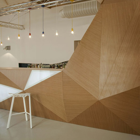
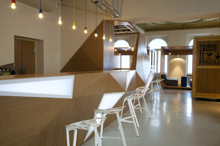
Hello, I'm wondering if someone might have some pointers for how to go about modeling a geometric/facetted counter like in the attached images. I tried experimenting with a subdivision object with edge creases, but it's somewhat cumbersome to add additional faces. Thanks for your help!
-
Thanks, glad I wasn't missing some obvious setting at least! Too bad there isn't a way to simply display a range of cells in a particular instance of a worksheet. For example, you could set a placed worksheet to display rows 1-60, another 61-120, etc. For now, I've placed the worksheet on a Design Layer with a Sheet Layer viewport cropped to the rows I want to display. It sort of works, but if the row heights change at all (from adding an entry that wraps to a new line) then I get a row half cut off.