HEengineering
-
Posts
478 -
Joined
-
Last visited
Content Type
Profiles
Forums
Events
Articles
Marionette
Store
Everything posted by HEengineering
-
2020 Teaser Tuesday - VGM Level of Detail - Vectorworks 2020
HEengineering replied to JuanP's topic in News You Need
Certainly one of the things I was hoping for here. Tho we have to wait and see how it truly performs in certain workflows. Wondering if this could improve site models as well? Also wondering if the issues with contours skipping over certain vertices has been resolved? I know many were experiencing this. For us we actually chose to stick with 2017 for site models as we felt it provided more accurate site models based off provided survey data. -
Service Pack 3 for Vectorworks 2019 released
HEengineering replied to PVA - Admin's topic in News You Need
Is this what the none class was created for?! We never were able to understand it. If I follow correctly your saying that all symbols created on none will actually accept the attributes of the class they are placed on ONLY when the symbol content is designed on the none class?? This has always been quite the annoyance for us. -
Camera Match Photo import orientation
HEengineering replied to HEengineering's question in Troubleshooting
I was able to resolve my issue by simply saving a copy and re importing. -
Rendering Concerns, need help with a broken file.
HEengineering replied to Jesse Summers's question in Troubleshooting
do you have a file you can share or maybe a bit more info with some screen shots? -
Ive never see that "Ground Plan" is there a way to activate and deactivate? I often find myself needed to verify if Im at z=0
-
Redering Textures on Structural steel
HEengineering replied to HEengineering's question in Troubleshooting
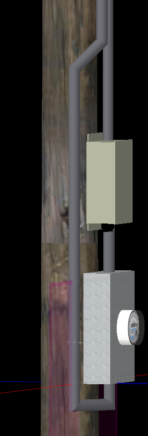
For the most part we really like Vectorworks as its so versatile. From CD packages to renderings and photo sims, it can all be done in VW. For us that over shadows some of the other issues, but sometimes you can go down the rabbit hole quick! Most the time Im modeling this for a camera match setup (making it not all that critical beyond textures), which is also a great tool. Camera Match alone has been a huge game changer for us in terms of efficiency and flexibility. -
Redering Textures on Structural steel
HEengineering replied to HEengineering's question in Troubleshooting
Many thank Wes! I guess it would help If I knew there were 3 different ways to get a beam. Yikes (now that you mention it Im doing a bit of a face palm because I should have recalled this) My findings mirror yours, I guess the problem is I was using the "wide flange 3d". Ill grab the new structural member tool and give that a go. -
I find it almost impossible to do this. When I set it by class it often does not apply to the steel. When I try and add the texture to the steel in the render tab that doest seem to work either nor does the eye dropper tool apply a texture. Some textures seem to have the rotation and scale sliders under the OBJ info render tab others don't?? I simply want to render a galvanized texture on all 4 beams so that it looks the same.
-
Best Methods for Extrude along path in multiple planes?
HEengineering replied to HEengineering's question in Troubleshooting
Soooo. I tried this at home with the same versions of OSX and VW and I do NOT get marquee selection in Nurbs edit mode. So I think its fair to say its certianly a bug somewhere, very odd behavior. I do get the marquee in polyline edit mode tho. -
Best Methods for Extrude along path in multiple planes?
HEengineering replied to HEengineering's question in Troubleshooting
It seems to work for me regardless of the vertices type. Can only speculate that it has to do with the fact Im on High Sierra and VW 2017 SP5?? To be honest I recall having this function in 2016 as well. Never been an issue for me. Are you guys both on 19? We are still refraining from upgrading. We had some issues with moves from Sierra to High Sierra. 17 seems pretty stable for us at this point so we never leaped forward. 18 had alot of site model issues which use that feature enough to warrant staying in 17. 19 seems like a headache with Mojave. Talk about upgrade fatigue🤒 Im really suprised this is an issue. -
Best Methods for Extrude along path in multiple planes?
HEengineering replied to HEengineering's question in Troubleshooting
Well ya got me. Maybe try a shift and click? Hoping someone will chime in bc it should be something you can do. I can't imaging what would be causing the issue? -
Best Methods for Extrude along path in multiple planes?
HEengineering replied to HEengineering's question in Troubleshooting
Hmm that seems odd. Im on a Mac? But it would be very strange that both platforms didn't have this function?? -
Best Methods for Extrude along path in multiple planes?
HEengineering replied to HEengineering's question in Troubleshooting
When in the mode just click and drag. I mispoke, you don't get a lasso you get a selection box. See my quick clip below Screen Recording.mov -
Best Methods for Extrude along path in multiple planes?
HEengineering replied to HEengineering's question in Troubleshooting
Follow Bensons suggestion. If you use the lasso too while in the editing mode you can grab just the nodes you want to move. Whether you want to include the corner or exclude the corner it can be done. Double click, grab the lasso tool and try grabbing just a few nodes you should see how it works. Once selected you can grab them as a group and move that segment. Also as Benson said you can alter the type of node it is. Or vertices if thats what you call them. -
Best Methods for Extrude along path in multiple planes?
HEengineering replied to HEengineering's question in Troubleshooting
Yes that is the case. So it may not be a viable solution in every case. For me It got the job done. It would be great to have a more flexible 3d conduit editor if you will. I also am no nurbs expert. I find that is hard to know when to use one? I think I even tried to extrude along a nurbs and it didn't work?? I could be wrong. -
Best Methods for Extrude along path in multiple planes?
HEengineering replied to HEengineering's question in Troubleshooting
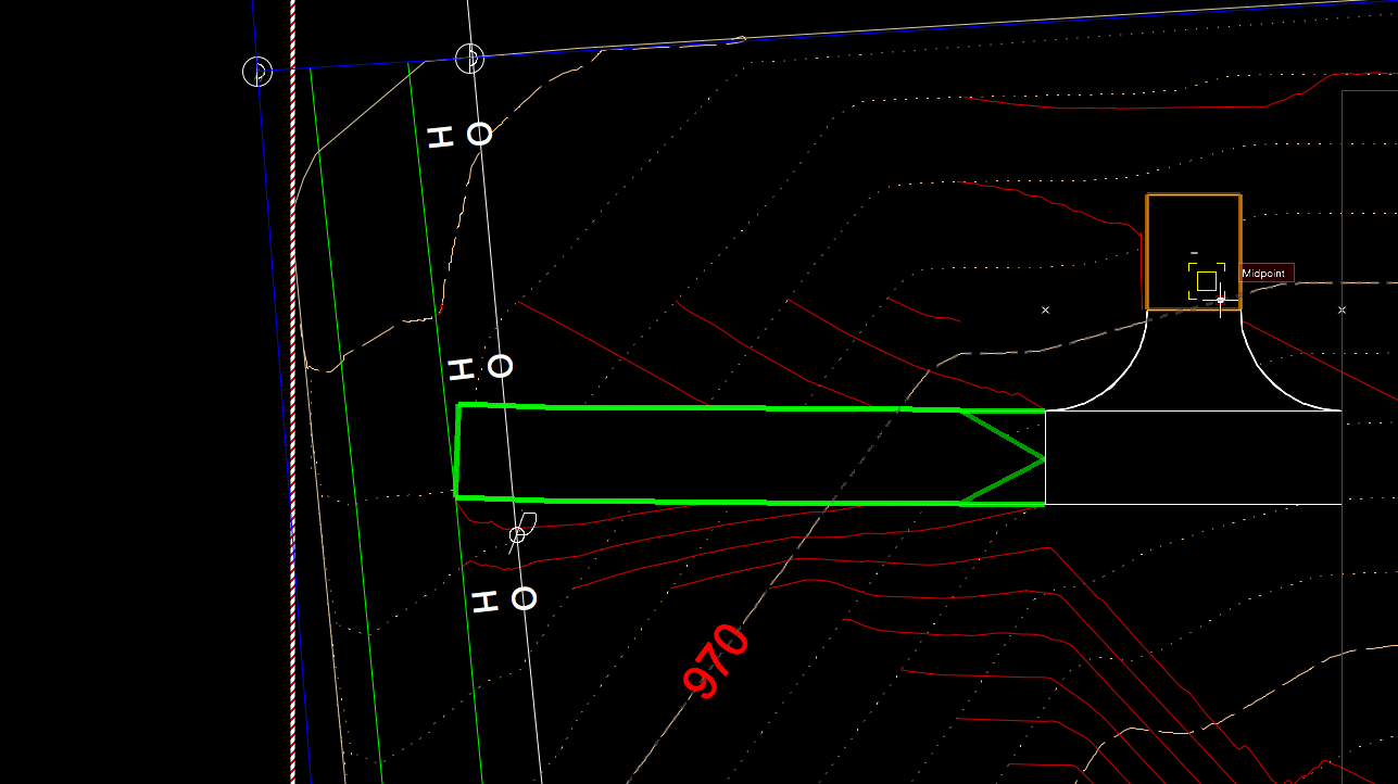
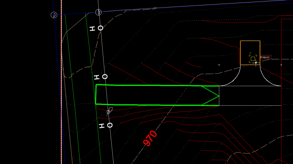
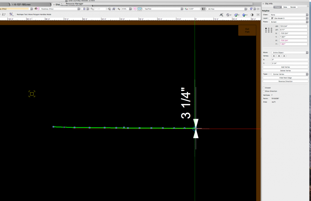
I know Im hijacking my own thread here, but here s a quick screen shot of a road and then the editable path. When in the path Im clearly looking at a Y elevation or the "side" of the road. However none of those nodes actually present any real elevation, or relation to 0. So what is the point of this edit mode?? In the model view the pt is elev 692. In the edit mode its 3 1/4"? So again what is the point of this edit mode 🤕? Adding another level of weirdness is This editable path view is actually shown in "Top Plan"🤦♂️ (see final attachment showing this)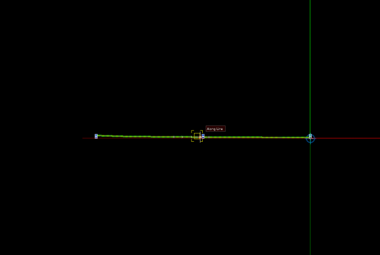
-
Best Methods for Extrude along path in multiple planes?
HEengineering replied to HEengineering's question in Troubleshooting
@line-weight you can actually put a radius on them. You have to double click and get into the path editor dialog. From there you see just the single line. (this is after the extrude along path has been completed). Once your in to the path you can use the fillet too actually. Which I would have normally not tried bc I assumed it was a 2d tool only, based on past interactions. It kinda feels like one of those workarounds that is not so intuitive unless you have years of knowledge that tells ya sometimes VW will allow you to do things you otherwise thought it couldn't do. I find that its a lot of trial and error when it comes to editing the path of a 3d object, this is also a battle I have on occasion with roadways on site models. This is a little off topic but I still don't understand why you can double click a roadway to get into the path, but at that point it seems pretty much un editable, yet your in an edit mode? Which makes me think there is a way, its just not intuitive as to what you can actually edit? -
Best Methods for Extrude along path in multiple planes?
HEengineering replied to HEengineering's question in Troubleshooting
That's essentially what I did. Just moving from view to view. You can't really your the set working plane tool tho on a line. So the only way it seems possible is to rotate around to the view you need. The challenge always seems to lie in knowing when you can use what tools and I guess one thing I liked about AutoCad w the plane icon in the upper corner which just gave you a better sense of where your at in space. VW is one one the more unintuitive when it comes to this specific operations. I had to draw in segments. Because as far as I can tell you cannot switch planes while in an active 3d Polygon command? So if you wanted to make this a continuous line in a co-planar fashion you must..? 1 draw segment to segment 2 Use the combine connect tool to convert it to a 3d poly 3 extrude along path 4. edit the path if you want any radius at the bends. I was hoping for a more efficient way I guess? -
Best Methods for Extrude along path in multiple planes?
HEengineering posted a question in Troubleshooting
This is something we don't deal with a lot. I have been able to do it in some scenarios, but if often seems very difficult. Can anyone provide some insight on the best way to say do a conduit run that moves across various vertical and horizontal planes? Also I notice if I draw the path in segments and try to convert them to a 3d poly, to form a path I get a group? But when I use the connect/Combine tool, which also converts it to a 3d poly it doesn't group them, but makes them all combine into one path. Seems odd that both don't give the same result? And one I have the line all combine It seems I cannot go into edit mode and put a radius on any of the corners??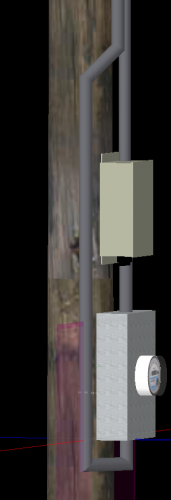
-
I came across this yesterday. There is a segment on UI and it discusses on screen widgets and floating pallets which pop up at cursor locations. When can we expect to see these features come to life? They look interesting, from what I can tell these are not yet features available?
-
Custom Line style difficulty :/
HEengineering replied to HEengineering's topic in General Discussion
Could be. This resource browser is intuitive in some ways, and completely confusing in others. Ive been a user for over 10 years and sometimes I still don't understand what the heck its doing! -
Custom Line style difficulty :/
HEengineering replied to HEengineering's topic in General Discussion
Well that at least helps me solve the riddle. Another of topic question. Seems like every time I move a resource from one favorite to the next via the resource browser it seems to always generate a "saved Views" folder? Im just moving the line style to another file yet it always brings one of these "saved views" folders along. -
Custom Line style difficulty :/
HEengineering replied to HEengineering's topic in General Discussion
Ok were getting warmer! I thought maybe 1:1 was what I needed to start at. Gets me a little closer. How about having the text be on one class and the line on another? Is this possible? -
I will start by saying we still work in saved views. Ive tried taking the standard gas line and duplicating it to make our own. I simply want to make sure the text size appears as 12pt, and would prefer this to be with a dashed line as opposed to the default solid line. I would also like the text to be on one class and the line to be on another. Im starting to think this is not possible. Heck if I could get the font to be 12pt that would be a start. However when Im editing the line style there is really no obvious correlation to how this is to be scaled. If I set it to 12 in the edit mode its much larger. Inversely if I try to set it down to .01 it looks close, but how can I actually verify the font size when I exit back out into the layer. This should be a lot easier to do imo.
-
Not intended to be smart. More curious as to how others approach. Looks great either way!