Macluskie
-
Posts
20 -
Joined
-
Last visited
Content Type
Profiles
Forums
Events
Articles
Marionette
Store
Everything posted by Macluskie
-
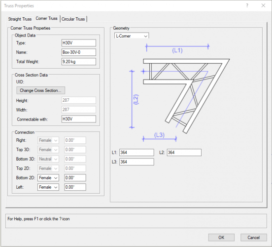
Found a solution using this symbol ...DOH Still don't understand what the "customise" Truss Properties OIP fucntion does though so any pointers on that most welcome :-)
-
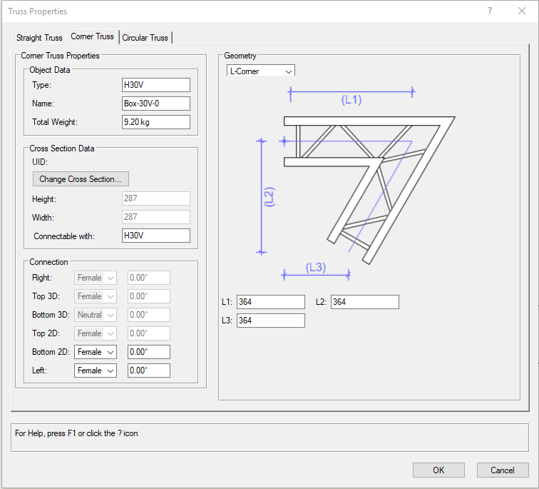
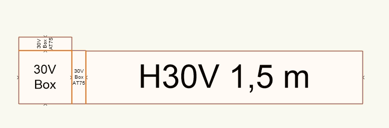
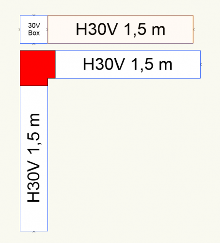
Doesn't seem to matter what size I put in the Custom Box the Box Corner and associated snap points remain the same i.e. the Naked Cube The red box is the size the corner should be
-
I have Prolyte Box corners in my the stock, a 289mm cube which conical couples can be attached to form anything from simple L corner to 6 way. https://www.prolyte.com/en/products/aluminium-truss/box-corners/box-30v-0-boxcorner-30v The Conical Couplers measure 75mm and so when assembled in a L corner for example measures 364mm x 364mm The Vectorworks Prolyte Library has the "naked" H30V box I've tried fiddling about in the "customise" settings in the OIP to create a simple L corner with the correct dimensions but cant seem to get it to work at all What am I missing? Thanks
-
NicoleD Not sure if this is what you mean but I was playing around with this ages ago and wrote this quick explanation to work out quantity, cost and weight of workshop 3D models https://paperclip.rcs.ac.uk/index.php/Worksheets I need to rewrite this for 2019 🙂
- 6 replies
-
- 1
-

-
- worksheets
- report
- (and 2 more)
-
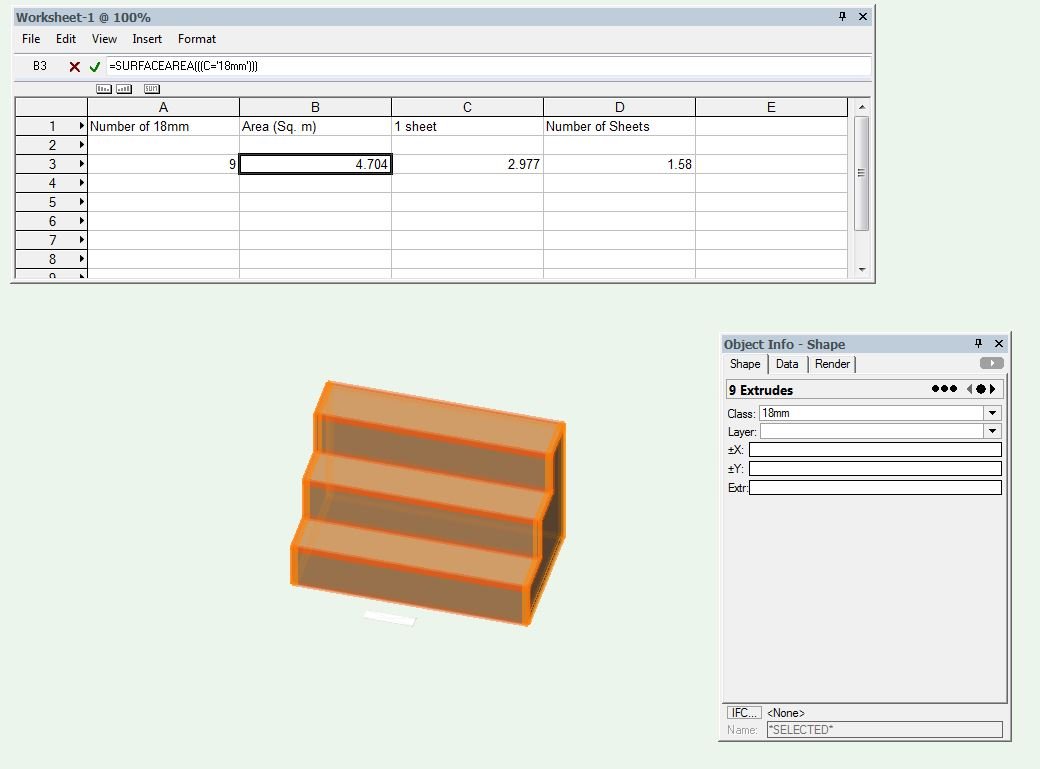
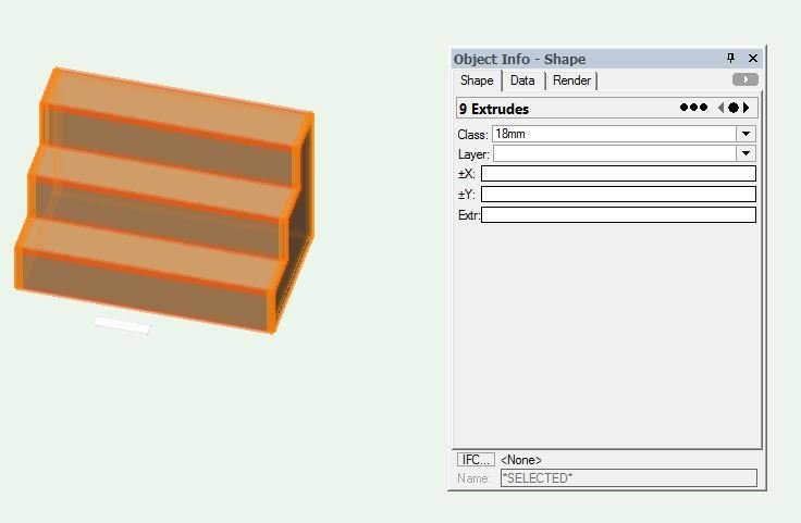
I was trying a little experiment to explore functionality of Worksheets I have drawn a 3 tread / step using 10 x 18mm sheet components all classed. pic attached (3 risers, 3 treads, 2 sides and a back) (pic1) I wanted to create a demo worksheet which will return surface data and tell me how many sheets of 2440 x 1220 18mm ply I will need I can create a worksheet which returns the SurfaceArea of the 18mm class but obviously that includes both sides and the thickness surface too (pic2) I guess I could divide the returned number by 2 to get a more accurate figure but it's not ideal I can see there is an "ComponentArea" function which states it can "The area (minus any holes) of one side of the components that meet the specified criteria" which seems ideal but it only appears to work on walls , roofs and slab objects Any help / tips appreciated Thanks all Steve

-
Has anyone else noticed (or reported) that the 1:25 scale is missing when "Create Multiple Viewports" is used? It's there when the single "Create Viewport" is selected. We get around this by changing the scale in the OIP afterwards but it's a wee bit of an unnecessary glitch which would be nice if it could be fixed Steve
-
Hi Here's a wee glitch that I can repeat every time in Vectorworks 2015 Can others check to see if it's my installation / machine Open a New File Start drawing a rectangle from approx 0,0 Input a large number into the floating toolbar (e.g. 5000mm x 5000mm) On my machine the rectangle will not size correctly IF I zoom out and do the same it works fine, it just seems to be a glitch if the rectangle is much much bigger than the visible Layer Plane Screen. Cheers Steve
-
Hi all I have a scan of a 3D object in .STL format I can use Meshlab to create a .3DS or .DXF, both of which I can import into Vectorworks 2015 The question is how to then manipulate the resulting model which imports as an incredibly complex mesh or incredibly complex (33000+) tiny polygons Is there any way to turn this object into something which is able to be manipulated with the standard 3D tools? (Deform, Fillet etc) Thanks all Mac
-
Thanks for that Looks like Stitch and Trim Surfaces works too :-)
-
Hi I have a complex 3D object made from several 3D solids I want to subtract a simple 3D rectangle from the overall object BUT retain the individual pieces I know I can do this by subtracting each individual component but this seems like multiple identical steps I don't think there is an option to Subtract Solids from multiple shapes in one go but does anyone have any suggestions to a workaround? Cheers
-
Just tried it and it doesn't count the symbol in the worksheet Function is "Image" Criteria is (for me) Symbol > Contains > (then use wee select symbol tool and you'll see a preview) OK that and add your equals sign and it will display the symbol image in your worksheet Hope that helps :-) Worksheet Example
-
I use the same workaround as JimW suggests when creating work sheets for my students Just switch away from Vectorworks being the active window by Cmd - Tab to Finder then do the screengrab OK, you wont get the nice blue radio buttons but it works Hopefully this will be fixed in the next version
-
Hello I'm aware of the Align and Distribute commands and the Duplicate / Move by Points Tool but my question regards to previously drawn objects. For example, If I have 4 different rectrangles representing paintings on an art gallery wall, I know I can align and distribute according to spacing but is there a way to distribute and define, for example, 500mm between paintings? Obviously, the move by points tool works but requires each object to be moved individually. Not too troublesome in this small example but scale up the problem and it'd be a right pain in the Vectorworks. Any help appreciated Cheers
-
OK, I might be a doughball but I cant get the hyperlink working in 2013 I create the hyperlink on the sheet layer pointing to another detail sheet layer The link works fine in VW2013 I batch convert and choose the two sheet layers But VW2013 throws up an error saying "0 or 1 Hyperlinks successfully exported" Any ideas? Cheers Mac
-
Mac OSX Command Shortcuts showing in Screengrabs
Macluskie replied to Macluskie's topic in General Discussion
Just did an experiment In 2012, on same machine, when you release the command key after the Command Shift 4 button combo the displayed shortcuts disappear and the menu reverts back to the image I want to capture On 2013, this does not happen, the keyboard shortcuts remain even after the command key is released Thanks for you help folks Looks like a key combo remap is my solution for now Here's a much better example of why its a problem, this screengrab would be used to explain the Create Resource menu...not very useful https://www.dropbox.com/s/juxqnnc8kl113o7/Screen%20Shot%202012-12-23%20at%2010.35.13.png -
Hi I've looked around for an answer but cant find one so seeking the help of you lovely people I'm writing tutorials for my students on an iMac and VW2013 Whenever I use the Command, Shift, 4 screengrab key combo the menus in Vectorworks also show the Command Key Shortcut as soon as the Command Key is depressed making the screengrabs a bit useless. For example here is a link to a "move by points" screen grab Any help to switch off the shortcuts being displayed most gratefully received Thank you Screengrab
-
Cheers mk How (and where) are bugs like this reported back?
-
Hello Just to confirm I'm not going mad could a couple of you try this with Vectorworks 2011 and post back. Open a New Blank Document Select the Double Line Tool > Top Control Line Mode > Create Polygons STARTING at 0,0 in the centre of the page try to draw a short line / rectangle Do you get a Triangle? (I've coloured it just for illustration) Any idea what's going on? [img:left]http://api.ning.com/files/*UbKCr8k-yHZ0HLqF391SJaTqGCNPitXOeFrV2TYpbFEdLz0CusZP*RxSubbRgA7TzqsOTsj4Qi3zMoUwTHJxu1Dx4*rgk5s/VWGlitch.jpg[/img]
-
Thanks guys I've decided to keep all the bars (pipes) as lighting positions and use either layers or classes to show/hide the ones used/unused. They are all on a layer which allows the Z height of the bar above the stage to be adjusted as a real trim height. Cheers again
-
Hello all I have a general question as a relatively new VW2011 user. "Once I have converted an extruded pipe to a lighting position, how do I convert it back to an "Extrude along path" again The reason for this bizarre question might be simple or solved by a different approach with some help I have a 3D model of a theatre with 30 counterweight bars. Any of which MIGHT be a lighting position depending on the show design. My instinct is that I dont really want to make them all lighting positions at the moment ( for example Counterweight 15 may be LX 4 and the renaming will get messy) but this may be the best approach? My thought was that only the specific bars, as designated by the design would be converted to light positions on a show by show basis but this throws up some other problems with Z heights of the newly created LX Position and the aforementioned de-creating of LX positions back to 3D extrudes. My other thought is that all Counterweight Bars are made LX Positions and those which aren't used are hidden by using classes to either hide the unused CW bars or only show the used bars. Anyway, I'm in a slight head scratching pickle and would appreciate any thoughts or ideas. Cheers