


rowbear97
-
Posts
207 -
Joined
-
Last visited
Content Type
Profiles
Forums
Events
Articles
Marionette
Store
Everything posted by rowbear97
-
I use the hardscape tool in Landmark to create soil volumes to quickly do takeoffs.
-

Send Objects to Surface...works sometimes, but not always
rowbear97 replied to ericjhberg's question in Troubleshooting
It is not the most efficient thing but to get around this CPU or GPU issue you may have to send the items individually. -
Alan is right this is a job for marionette! We too often try to show things, down to the paver, when in reality things hardly ever work out the way you want. Aside from that you indicate you want to design a random pattern. I professor of mine congratulated me one time when I said these very same words. He said that random pattern is an oxymoron. When confronted with this in preparing construction documents I would show a hatch that has nothing to do with the overall design and then either create a written description, as you have, or show a small vignette of the desired effect.
-
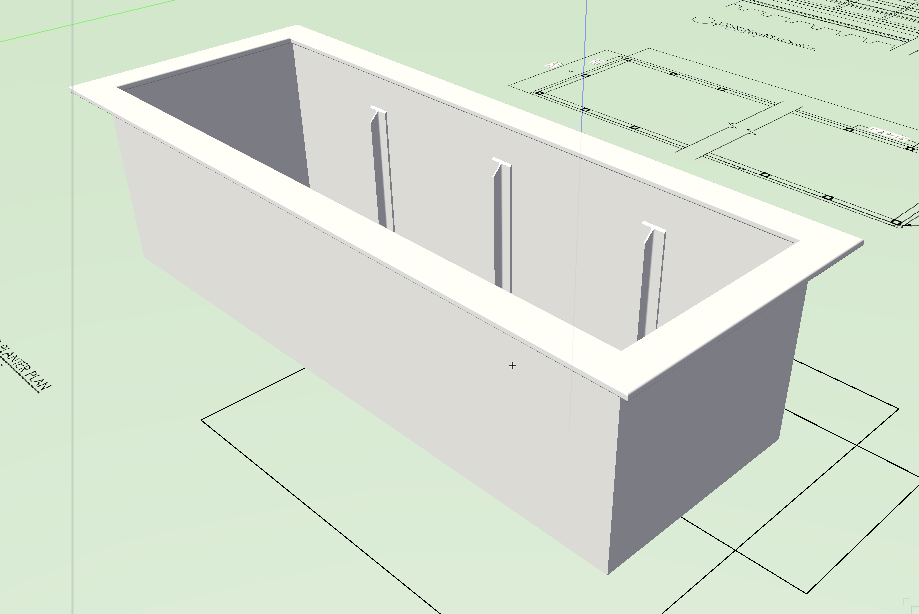
Perhaps I'm stuck too much in the past but for details that are common place, paving sections, planting details, things that are repetitive I and my clients usually use 2D files that are standardized in scale and content in an effort to give a uniform appearance and cover the detail sheet uniformly. I have encouraged my clients and I have personally implemented using 3D when creating a unique item for a specific project. In this way I can communicate the idea to the client in 3D models with textures and materials applied. As the 3D model matures and we move forward we continue to refine the 3D model and add parts to some of the detail sections as shown in the attached. This planter started as a simple extrude and evolved to be in the final construction documents. The attached sheet has a combination of what Eric Berg recommended and the 3D approach with one variation. My client wants the drawings customized per project to account for variables like paver thickness or soil composition therefore they do not reference the standard details but import them into there files. Hope this helps. L-503-Roof Terrace Wood Fence & Community Planters.pdf
-
I have often tried this method but find that, as the gentlemen point out, drafting the centerline ensures that you get consist radii tangent alignment.
-
Need help designing Roads with Landmark commads
rowbear97 replied to Jose E. Calderon's topic in Site Design
Jose, I agree that the road tool and road grading method needs improvement. I just went to try out your file and found it is no longer available did you get your issue resolved? I would be willing to look into if for you. -
nca777, Looks like Revit will create a site model from 3D contours. I'm not sure you can need to export the DTM as an IFC.
-
nca777, I went through this entire string and perhaps I missed something. Perhaps the issue is with your original approach in importing the "cad file". Do you have the option for the surveyed to send you the TIN instead of his output of contours? I have found if you can get this you will have much more accurate site-model. I would also recommend that you draw you site-model boundary before creating the site model.
-
When importing into VW do you have your units set to the desired scale, e.g. 1:500 or similar? I have found that this sometimes eases the pain. If that doesn't work can you have them send you the file in parts? If that doesn't work I would be happy to give it a shot! Signed, Your cousin from across the pond!
-
Not to confuse things but this is the other Robert Anderson middle initial D. Robert is correct that a best practice is to create the "shuttle file". I have often recommended to my clients to use this approach and it seems to work. As of 2017 release your approach of importing and deleting is the only way. If as Robert suggests you use a "shuttle file" your visibilities will remain the same and you will not have to deal with that too much, unless your MEP adds layers or is sloppy on the drafting. Prior to version 2014 this was the only way to handle DWG files but now you can reference them seamlessly. Best of luck! If I can be of any further assistance please feel free to contact me.
-
I have used Keynotes and Legends on several projects. My current dilemma is I have a drawing file with keynotes shown in the annotation viewport but no Keynote Legend. I have tried to take a legend from another file in the same project and create a new file and keynote legend yet I can not recreate or restore the Keynote Legend. Has anyone else come across this issue and do you have a fix?
-
Not sure what it is you are looking for. You can draft a polyline and change your mode from lines to 'tangent arc mode' and type in an exact radius by hitting the tab button while drafting in that mode. Once you have created the desired centerline off-set those polylines and close you shape then use the Landmark>Create Objects from Shapes to produce a road, site element, hardscape, etc. If you have an image or a file you want to share I can help more.
-
Thanks Pat. Your example is a good one yet I was hoping....
-
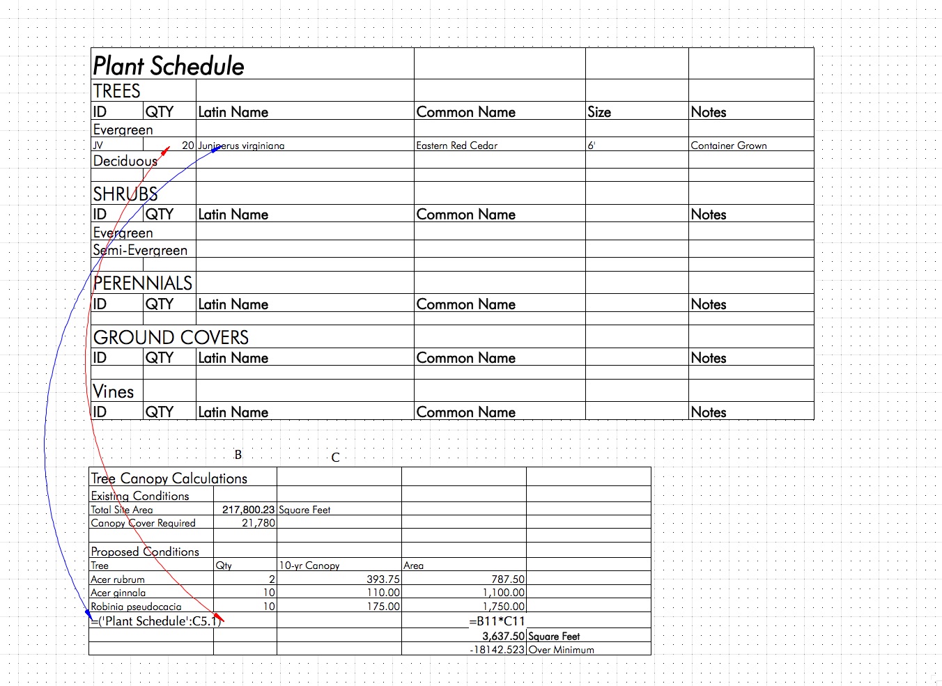
Thanks for the follow up. I did not phrase my question correctly. It is simply that when I try to connect the result of a report into a worksheet that has a function my entry seems to be incorrect (see attached screen grab). I want scientific name and the quantities from the plant schedule to propagate in the "tree canopy calculation" worksheet and then have the calculations done with ultimately the sum of the total. In this current version the cells have values that I enter manually and the calculations done by functions.
-
I too am working on leveraging the power of worksheets and reports and have, perhaps the most basic of questions. I am going to want to take the quantity of plants from my plant schedule and use a worksheet to calculate the canopy coverage each tree earns you a credit in area for that species. I want the worksheet 'canopy coverage' to update when I recalculate after I've added plants to the plan. My earlier attempts at this have failed. Would anyone be able to help?
-
I haven't tried this yet my self but thinking about vertical road alignments and the approach we took when I was a young lad would be to define the slope of the centerline. Perhaps you could create the road centerline and offset for curb and gutter. Use as site modifier and assign a slope for each polygon. The last time I did a complex grading plan for a develop larger then this was i used pads for the road assigning the slope and or cross slope as they changed from, lets say 2% to 5%. The resulting solution didn't give me the changes at the curbs but it did give me accurate cut and fill volumes.
-
Should be easy enough right? Layout horizontal alignment, create site model section, layout tangents for vertical curves, have parabolic curves generated using either symmetrical or asymmetrical curves, create road cross section, extrude along path, object becomes site modifier, interacts with site model, done!
-
In Allan's image of the spreadsheet can you identify the columns? It looks like the first one is data point and then LAT and LON with elevation and description. If this is the case then delete the first column and last and you should be cooking with gas! The only issue you will have is the conversion to you current site coordinates.
-
After following this for a while it brings me to my wish list item. GeoPack and Civil 3D have vertical curve tools. Why can't we have a the same. There is nothing like having a nice parabolic vertical curve on your roads. I'm going to show my age here by saying that we used to do this by hand when I was working in Pennsylvania and we did horizontal and vertical curve alignments. I've started to kick this around and I feel like there should be a script for this. Anyone have thoughts on this?
-
here is a plant schedule that i have created for one of my clients that you can use as a template. do be careful about the plant categories. a common issue is that either the plant is in a category that is not what you want or in the, very rare instance, there is a spelling error. plant_schedule.vwx
-
Wouldn't it be great if we could layout streets/ driveways/ roads with vertical curve alignments? My wish, aside from world peace, would be to have the ability to create 3D polys that use all the geometry of vertical curves that you would use in road alignments. I've included description from a college course on the subject and a spreadsheet from Michigan DOT that will run the calculation. I use to do these by hand when I first started as a designer in a landscape architecture firm. The built result is a smooth and beautiful transition that avoids abrubt grade changes. GEOMETRIC DESIGN of CURVES.pdf MDOT-Vertical_Curve_Calcs_120887_7.xls
-
Is there any new information on this issue? I'm still experiencing problems with image props working properly.
-
I've been running on Sierra for a few weeks now and haven't had an issue until 10.12.3. When that was installed the operating system was crashing! It would should down and restart and perhaps with our without coincidence I was running VW at the time. I'm running a Mac Pro (Late 2013) with the following. Just be aware this may be an issue. Apple support hadn't heard of there being any issues and hardware as eliminated as the culprit. Processor Name: 6-Core Intel Xeon E5 Processor Speed: 3.5 GHz Number of Processors: 1 Total Number of Cores: 6 L2 Cache (per Core): 256 KB L3 Cache: 12 MB Memory: 32 GB
-
Rather than relying on Google you could also get the DTM information from GIS at http://data.geocomm.com where you will find USGS sources. Also have you checked with your local government? It is possible that you can get GIS shape files for the terrain in question along with roads and other items.
-
Thanks for getting back to me. I really need to get my understanding of worksheets up to speed. I've tried what you suggested and still can't get the result I want. I'm going to use an alternate method for the time being as I have a deadline that I'm trying to meet. Again thanks for your time.
