
rowbear97
-
Posts
207 -
Joined
-
Last visited
Content Type
Profiles
Forums
Events
Articles
Marionette
Store
Everything posted by rowbear97
-
@nca777 I did a little more investigating and while I wasn't able to export the site model as an IFC I did come across a way to get a fairly clean 3D Polygon version. When exporting you site model make sure that you have changed the site model 3D visualization to contours no mesh. Once you have done that you export as a 3DS file. Bring that back into Vectorworks and you will then be able to select the triangular 3D polygons and deleting them leaving behind only the contours. Hope this helps.
-
While @Alan Woodwell options is viable you may find out that you will need to use a combination of pads and grade objects. I often end up using pads to get the right slope and cross slope for larger areas and then use contours and other grade objects to get the desired effect.
-
I keep seeing posts in MacWorld and the like for external GPU's for MacBooks. I know this is more for gaming but any pickup in speed for graphics would be better is something you have considered?
-
Also make sure you have moved the origin by going to Tools>Origin>Center on Internal Origin this may help in size but definitely rendering.
-
@jnr I'm available for assistance. Only familiar with the area as we lived in Richmond for 8 years and my wife went to Darden for her MBA. Glad to help.
-
@JohnAthaydedid you get this to work to your satisfaction?
-
Matt, Shameless self-promotion here! Check out my tutorial here to get tips and tricks on importing and referencing DWG files. Additionally an updated version for VW 2018 will be coming out soon.
-
I have tried both the "Driving Curve" and the "Vehicle Swept Path" and while the tool seems to be working correctly I am not getting an outline as shown in the video. I have tired various settings within the OIP and to no avail. This needs to be fixed.
-

How to create a double staggered row of Carpinus hedge
rowbear97 replied to Andre Gardner's topic in Site Design
Andre, I don't think there is a way to do this with the hedge tool. You might have to run two two lines and stagger the start point. Or you may not have them graphically appear exactly as intended but note on the drawings that these items are staggered. -
You are welcome @JohnAthayde. Hope everything will work out for you.
-
Marissa thanks. A limit of 8 seems kinda lame. Are there plans to up that number? When you say Renderworks you are indicating selecting one of the other rendering modes light Exterior Realist Fast or Final right? When I do that the emitted light still doesn't show up. What am I doing wrong?
-
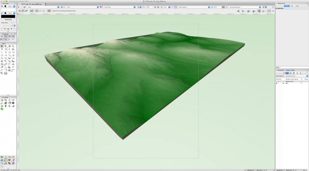
John, Under Y2013 I chose I've successfully downloaded 'Topography - 2 foot Contour Interval format Shapefile. Start a blank file create a class for contours. Go to File<Import<Import Shapefile. Select the downloaded tile (it is broken down into a grid I've tested 059 and 060) and click Open. Change to Design layer or one of your own choosing or it will create one from the file. Select the created class for contours and click Ok. Landmark will take it from there. Tile 60 would appear to be Ivy and 250 interchange and a good part of Campus including the Darden School. Make sure you change you plan scale to 1"=100'. Also change your origin as these tiles seem to be set to the state grid, by going to Tools<Origin<Center Drawing on Internal Origin. This will keep the coordinates the same while making modeling more efficient. If you continue to have issues you may want to change the origin entirely keeping in mind that this will make exporting or sharing back to the state plane very difficult. At this point you might want to change your view to Front to confirm all the contours are at elevations (this is also good to do to check for anomalies in the data). Check for groups and un-group these objects, selecting to attach records to these items. The contours will not be all connected, but if you are making a digital terrain model it will not matter. You might want to simplify the 3D polys. Select all 3D polygons and create you site model. Depending on your needs for planning purposes or other do choose wisely as just modeling tile 59 (Ivy) at 2' contour interval took my machine some time to complete. Best of luck.
-
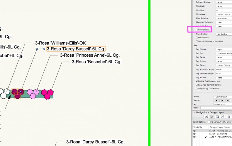
Andre, You need to make sure that each plant has "On Plant List" checked, see attached. Once you do that your plant counts will be accurate.
-
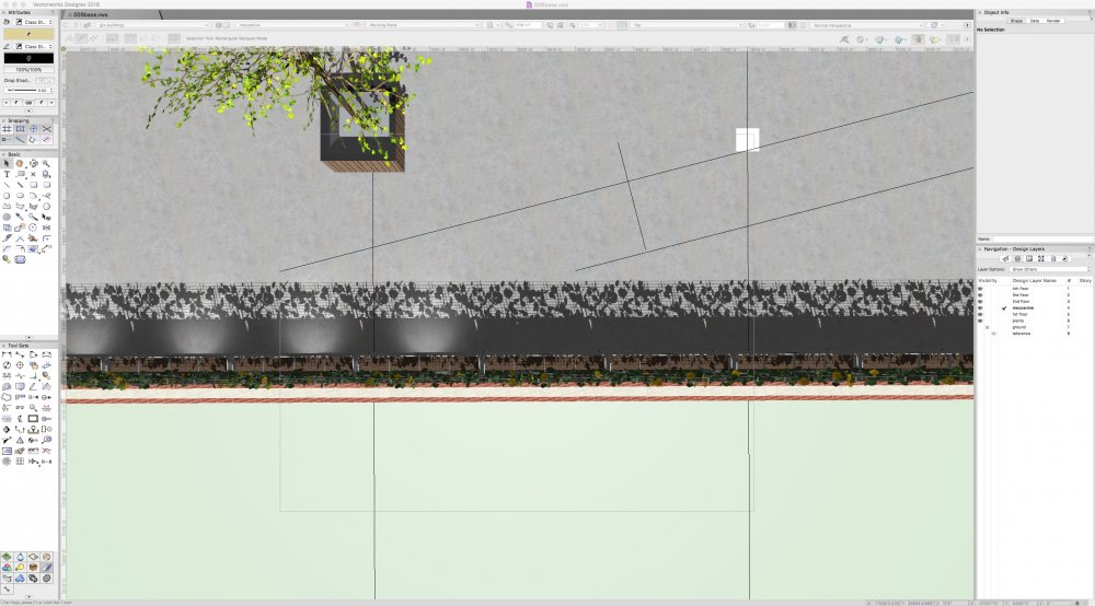
I will confess that I'm not that efficient with light sources to the point where I can't get a custom source to show light in any rendering mode. I'm working on a project where we will be providing path lighting with small fixtures fit into new planters. I've modeled that planter to include the a standard "flood" and as you can see in the screen shot some of the are showing up while the same exact symbol suddenly stops rendering the light. Is there a limit to the number of light sources or some setting that I'm missing? Any help will be greatly appreciated!
-
John, I'm going to back up a bit here. I have worked extensively in the Great Commonwealth of Virginia and have some experience in counties near you. How did you come to get AutoCAD files from the County GIS office? I might be mistaken but I think that you may have better luck if you request and import Shapefiles of the same data set as they may come with contours rather than points and breaklines as you have shown. If you have a contact in their GIS department ask if they can't give you Shapefiles and see how that turns out. Best of luck.
-
@WillofMaine I have the same year but different specs on my Mac Pro and I haven't experienced anything unusual like you describe. I also us a Macbook Pro 13" with i5 processor and minimal video and haven't really noticed that much of a difference. I too am considering replacing the trash can with the iMac Pro but my CFO/wife wouldn't be too happy! ;-)
-
@zoomerWould it be possible to use a worksheet to select objects without IFC tags and then edit from there?
-
@Stu Wilson Not sure if you have resolved this by now but I have a similar issue in that for Construction Documents the fancy graphics are too much. Having also been in the field as an installer I prefer simpler graphics and one of my Clients also prefers simple graphics. For this reason we have created custom symbols that simply have different shapes at the centers to differentiate plants from one another. It is really very simple to create your own by starting with one of the less "hideous" and draft your own shapes.
-
@mgries You are absolutely correct this would be helpful. For this reason and some others I upgraded from Landmark to Designer to have full access to all the Architecture Tools as I often have to model my client's homes when doing a design.
-
Most efficient way to model thousands of trees?
rowbear97 replied to Christiaan's topic in Site Design
You could make the cross plane trees a hybrid object with the tree canopy showing only in top/plan view and use the drop shadow setting to get the desired shade effect. -
You need to hire a Landscape Architect who is using Landmark or Designer! I don't have an answer to your question. Just wanted to put that out there! :-)
-
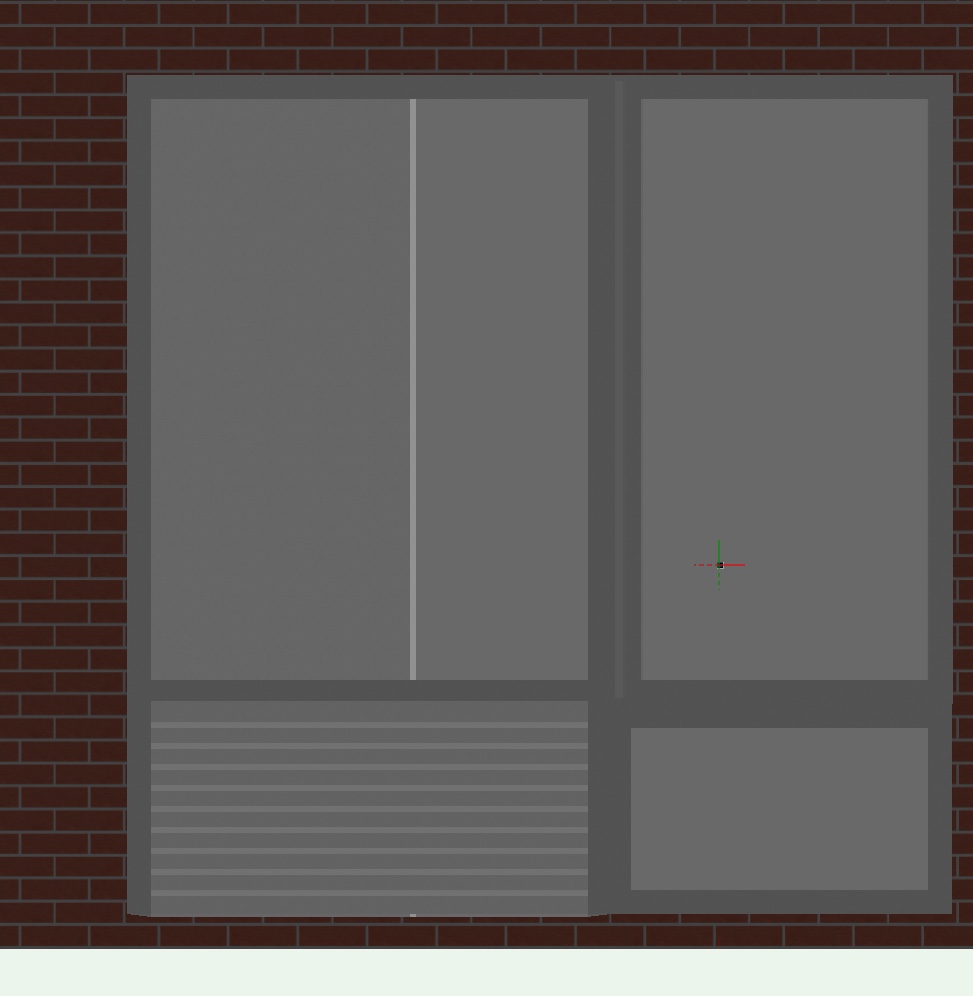
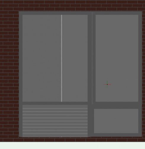
Perhaps I'm going about this the wrong way. I have a mid-rise residential building that I'm working on and I'm having to recreate the elevations by hand. Each "Window" consists of (see elevation01) fixed lower window, vertical pivot above, fixed larger window with louvered opening for PTAC. I would like to take these four elements and combine them into one symbol that I can insert into walls as this assembly appears on 50 of the 57 units. Any suggestions or assistance would be greatly appreicated.
-
VW 2018 - Plants and IMAGE Function in Worksheet
rowbear97 replied to ericjhberg's question in Known Issues
Eric, Had worked through what I thought was a solution, see below, yet this seems to elude me. I even tried changing elements in symbol from screen to group and all this managed to do is make the image in the worksheet show partially correct and still not perfect. I don't know what else to do. I believe it to be a video issue as now I'm able to make the worksheet show correctly but the design layer information still misbehaving. Started with your instructions and everything happened just as you described. When looking at the Symbol in the resource browser there is only the name no thumbnail. If I change the view to OpenGL then it appears. If I right click and select edit then 2D Graphics while on the design layer the canopy can be selected but nothing shows up in the OIP. Once I exit out the visibilities go back to the way the should be as shown in the Navigation Pallet. However if I then recalculate the worksheet the visibilities return as before with those classes shown as off but still visible. I then edited the 2D symbol from the resource manager and changed the canopy and tree box to Polygons. I thought this resolved the issue with the viability when recalculating the worksheet; however the tree box still shows up even when the visibility is off. And if you zoom in or out the classes that are off show back up. -
VW 2018 - Plants and IMAGE Function in Worksheet
rowbear97 replied to ericjhberg's question in Known Issues
Eric, Don't know if I have an answer to your problem without perhaps giving it a look at personally. Is this something you would be able to share, or at least part of it. I will try to recreate on my own in the meantime to see if it happens on one of my drawings. -
Was just a bit curious about this from a perception standpoint I thought 2018 was slower. I timed it just now and 2017 was just only faster by a second or two. I have encrypted my drive and I'm running High Sierra on a Early 2013 Mac Pro with 32 Gb of RAM. Both installs are custom with Designer and take nearly 43 seconds.