


MullinRJ
-
Posts
1,992 -
Joined
-
Last visited
Content Type
Profiles
Forums
Events
Articles
Marionette
Store
Posts posted by MullinRJ
-
-
Hello @Letti R,
Yes, it is definitely a bug in VW 2024. I just filed a bug report for this, VB-203576, and cited this Forum post. If/when I hear anything I'll post back.
For the moment you will need to shuffle resources between the old folders and the newly created nested folders. However, you don't need to shuffle things around initially as much as you describe above. Instead, create your new nested folder structure with dummy names, then move everything from your old folders straight into the new folders with SetParent(), which does work with moving resources between folders. When everything is moved, delete the two old folders and rename the dummy folders with the old folders' names.
There is a caveat, there is always a caveat, if either of old folders contain nested folders you will have to create the finished folder hierarchy before you start shuffling anything, then very carefully move everything from its starting position to its final position, which can get tricky. I hope your two starting folders are flat (only contain resources.)Best wishes,
Raymond
-
 1
1
-
-
Hello @DCarpenter,
Immediately after EndXtrd, get the handle to your new object with LNewObj.
Create two new variables: "Hxtrd" to store the handle to the Extrude; and "Hdup" to store the handle to the extrude duplicate.
PROCEDURE xxx; VAR Hxtrd, Hdup :Handle; BEGIN BeginXtrd(5", 10"); Rect(0, 0, 24, 12); EndXtrd; Hxtrd := LNewObj; { handle to the extrude } Hdup := hDuplicate(Hxtrd, 0, 0); { handle to a duplicate extrude } Move3DObj(Hxtrd, 40, 20, 30); { move it anywhere you want } SysBeep; { make noise when done } END; Run(xxx);Raymond
-
Hello @FMA,
I don't believe you can write to your open READ file. You will need to close it first, and reopen it with Rewrite(), or Append(). Then you can write to it. Rewrite() will write over any existing data, and Append() will add to the end of existing data. Don't forget to close it again when you are finished writing.
HTH,
Raymond
-
1
-
-
Hello @Arnold_Hoekstra,
I tried opening your file in several versions of VW and MiniCAD (VW12, VW8, MC7, MC6, MC5, & MC4) to no avail. It appears the file is damaged. Do you have another copy?
When I downloaded the file, it had no File Type or Creator codes assigned. I added MC+4 / CDP3 for MiniCAD 4 &5 files, which did not work. Then I tried MC6d / CDP3 for MiniCAD 6 files. This also did not work. I got one of two messages, "This file is damaged!", or "Resource Manager error!". If this is your only copy, you might want to send it to the VW engineers to see if they can resurrect it.
Good luck,
Raymond
-
1
-
-
Hi @Dave Donley,
I just took a peek at the file you uploaded today. It opens in VW 2024, but there is nothing showing. The Resource Manager has 10 LineStyles, and two Textures (Water Bright, and Water Dark.) Also, there is one Design Layer, visible, and two Classes (None and Dimension), both visible. Would you please verify on you end?
Thank you,
Raymond
-
Hi Sam,
On a Design Layer, I don't think so. In a Viewport, maybe, but probably not by the PIO's control. Others may prove me wrong.
Without knowing more of what you are trying to achieve, I don't know what else to add.
Raymond
-
Hello @ge25yak,
There may be other ways to set the wall height, but I found this works, so I stopped looking for other ways. The commands below always use mm, so you have to convert your document units to mm before setting the wall height values, hence the use of the scale factor variable "SF". This overly simple script will change the selected wall height to 5 (document units). I assumed meters in this case. Using your document units change the "newWallHt" value to your liking.
import vs # Sample script to set the height (top elevation) of a selected wall. newWallHt = 5 # document units WallStartHeightTop = 604 WallEndHeightTop = 606 WallStartHeightBot = 605 WallEndHeightBot = 607 SF = vs.GetPrefReal(152) / 25.4 # units per mm H = vs.FSActLayer() vs.SetObjectVariableReal(H, WallStartHeightTop, newWallHt/SF) # starting height in mm vs.SetObjectVariableReal(H, WallEndHeightTop, newWallHt/SF) # ending height in mm vs.ResetObject(H) vs.SysBeep()HTH,
Raymond
-
Hi @Andreas,
Yes, that is the call to insert a symbol/pio into a wall.
Using VW to help reverse engineer the code, I placed a Window in Wall and exported the VW file to a script file that defines the geometry. Use menu File>Export>Export Script...
This doesn't always work for complicated files, but for simple things it's a great way to see what calls are used and how they are arranged.
Here's a small script I built by copying the Wall and Window from the text dump (Export Script...). I found the relevant calls in the middle of the file and copied them to a new file, then rearranged a few calls and renamed the temp handles to make it easier to follow. Comments were also added for readability. To see what this represents, copy and paste this code into a script resource and run it. Then change some number, rerun, and notice the effects of the changes. It's a great learning tool for new commands.
PROCEDURE xxx; { Sample script to insert a Window into a Wall. The units are in mm. } VAR WallHandle, WindowHandle :Handle; boolResult :Boolean; BEGIN { set pen and fill attributes } PenSize(1); PenPatN(2); FillPat(1); PenFore(0, 0, 0); PenBack(65535, 65535, 65535); FillFore(0, 0, 0); FillBack(65535, 65535, 65535); NameClass('None'); { set class to use } Wall(-5400, 2000, 5000, 2000); { create a wall } SetObjectVariableReal(LNewObj, 604, 3048); { Wall Start Height Top } SetObjectVariableReal(LNewObj, 605, 0); { Wall Start Height Bottom } SetObjectVariableReal(LNewObj, 606, 3048); { Wall End Height Top } SetObjectVariableReal(LNewObj, 607, 0); { Wall End Height Bottom } SetObjectVariableReal(LNewObj, 621, 3048); { Wall Overall Height Top } SetObjectVariableReal(LNewObj, 622, 0); { Wall Overall Height Bottom } SetObjectVariableReal(LNewObj, 618, 152.4); { Set Wall Width } DoubLines(152.4); ClearCavities; { start with an empty wall } WallHandle := LNewObj; { save handle to the Wall } WallCap(FALSE, TRUE, FALSE, 0, 0); AddSymToWallEdge(LNewObj, 5300, 0, FALSE, FALSE, 'Window', 0); { insert object into wall } boolResult := SetObjWallInsLocOff(LNewObj, WallHandle, 0); { shifts object to inside/outside of wall } WallCap(TRUE, TRUE, FALSE, 0, 0); ResetObject(WallHandle); { reset the Wall object } WindowHandle := LNewObj; { save handle to the Window - not used, but could be used later } SysBeep; { make noise when done } END; Run(xxx);Here's the same thing in Python. Again, the code was gathered from text dump from the program using Export Script.
import vs # Sample Python script to insert a Window into a Wall. The units are in mm. # set pen and fill attributes vs.PenSize(1) vs.PenPatN(2) vs.FillPat(1) vs.PenFore((0, 0, 0)) vs.PenBack((65535, 65535, 65535)) vs.FillFore((0, 0, 0)) vs.FillBack((65535, 65535, 65535)) vs.NameClass('None') # set class to use vs.Wall(-5400, 2000, 5000, 2000) # create a wall vs.SetObjectVariableReal(vs.LNewObj(), 604, 3048) # WallStartHeightTop vs.SetObjectVariableReal(vs.LNewObj(), 605, 0) # WallStartHeightBottom vs.SetObjectVariableReal(vs.LNewObj(), 606, 3048) # WallEndHeightTop vs.SetObjectVariableReal(vs.LNewObj(), 607, 0) # WallEndHeightBottom vs.SetObjectVariableReal(vs.LNewObj(), 621, 3048) # WallOverallHeightTop vs.SetObjectVariableReal(vs.LNewObj(), 622, 0) # WallOverallHeightBottom vs.SetObjectVariableReal(vs.LNewObj(), 618, 152.4) # SetWallWidth vs.DoubLines(152.4) vs.ClearCavities() # start with an empty Wall WallHandle = vs.LNewObj() # save handle to the Wall vs.WallCap(False, True, False, 0, 0) vs.AddSymToWallEdge(vs.LNewObj(), 5300, 0, False, False, 'Window', 0) # insert object into wall boolResult = vs.SetObjWallInsLocOff(vs.LNewObj(), WallHandle, 0) # shifts object to inside/outside of wall vs.WallCap(True, True, False, 0, 0) vs.ResetObject(WallHandle) # reset the Wall object WindowHandle = vs.LNewObj() # save handle to the Window - not used, but could be used later vs.SysBeep() # make noise when doneOne caveat to keep in mind, LNewObj is a function that returns a handle to the last object created (usually — but Groups don't follow this rule when they get created.) Think of LNewObj as a temporary handle. If you want to save a handle for use later in the script, assign LNewObj to a program variable and keep on drawing. Notice "WallHandle" is used this way.
HTH,
Raymond
-
1
-
-
Hi @mgvwx,
I have not used the GIS calls in any of my scripts yet, and I don't know how much you know about scripting, but these are the commands in the GIS section of the Script Reference.
BindLayerToArcGISFS GISDimStringToMM BindLayerToWFSFS IsGeoreferenced EditGeorefWithUI LegacyShapefileExp GeogCoordToVW LegacyShapefileImp GeogCoordToVWN RemoveGeoref GetAngleToNorth SetDocGeoRefByUsrOrg GetGISOrigin SetGISLayer GetGISOriginN SetProjectElevation GetProjectElevation UpdateFeatureLayer GetProjectionLocName UpdateLayerFromFS GetProjectionProj4 VWCoordToGeog GetProjectionWKT VWCoordToGeogNYou can view them in the Developer WIKI online https://developer.vectorworks.net/index.php/VS:Function_Reference,
or in the HTML Script Reference located in you application folder .../Vectorworks 2024/VWHelp/Script Reference/ScriptFunctionReference.html
Do you have a sample file you can post? Smaller is better. It might help people try out some of these calls against actual data and give you some feedback.
Raymond
-
Hi @EBV_Nick,
Could you post an example file of your objects? It doesn't need to the whole file, maybe a few dozen symbols. The easiest way to create a sample file is to select a handful of objects, copy them, and paste them in place (Alt-V) in a new file. It will be easier to make suggestions if we can see actual data.
Thank you,
Raymond
-
11 hours ago, Pat Stanford said:
So the first object drawn will be at the bottom of the stacking order and will be returned by LSActLayer. The last object drawn will be at the top of the stacking order and will be returned by FSActLayer.
Hi @Pat Stanford,
It is the other way around. The first object drawn - at the bottom of the stack, yes - is returned by FSActLayer (or FActLayer, when selection is ignored.) The object at the top of the stack is returned by LSActLayer (or LActLayer, when selection is ignored.) Everything else is correct.
Good night,
Raymond 😉
-
3
-
-
In the same vane as @Pat Stanford's example, but using abs(a-b <Tol) to combine the (a < b+Tol) and (a > b-Tol) into one expression, you will need three comparisons.
This compares Rotation to Ang+0, Ang+180, and Ang-180, and tests them against a tolerance.
Tol = 0.001 if (abs(ObjAng - Rotation) < Tol) or (abs(ObjAng - Rotation + 180) < Tol) or (abs(ObjAng - Rotation - 180) < Tol):I think this covers all options. Change the tolerance to change the sensitivity of acceptable values. If you want to include values at the tolerance limit, then use "<=" in place of "<".
HTH,
Raymond
-
1
-
-
Hi @Pat Stanford,
OOPS! Yes, Pref 21, not 12. Thank you. I corrected it above.
It may be a bug, but as far as I can remember it has always worked this way. Annoying, it is! If you can get it scheduled to be "fixed", I and a lot of others will rejoice.
Raymond
-
You can use $INCLUDE statements in Palette Scripts, and in Plug-in Scripts. You can also set VW to recompile on each execution (VW Pref 21 – Developer Mode, or VW Pref 407 – ImmediateVSMode), but it is only "automatic" for scripts run inside Plug-ins. If you want to recompile a script that has an $INCLUDE statement in a Palette Script, then after you make changes to the disk file you will have to open the Script Editor for the script in the palette (Opt/Alt–Double Click) and then close the Editor with the OK button. No changes to the file are necessary. If you use the ESC key or click the Cancel button, nothing happens and the script will not be recompiled.
If you have your $INCLUDE statement inside a Plug-in and set VW to recompile for each execution, VW will automatically recompile before each execution, so you can make edits in your disk file and rerun the Plug-in. Your disk changes will be recompiled.
Bottom Line: The Automatic Recompile option for Palette Scripts is meaningless. It only applies to Plug-in scripts.
HTH,
Raymond
-
Hello @MGuilfoile,
Like you, I enjoy using the Screen Plane while drawing in 3D. If your problem in not related to the Clip Cube, how do you have your Document Preferences set for Legacy 2D drawing? I use the following settings and enjoy the older style of drawing that used to exist. I don't use Clip Cube, so I cannot comment on its interaction. Please write back and share your findings when you can.
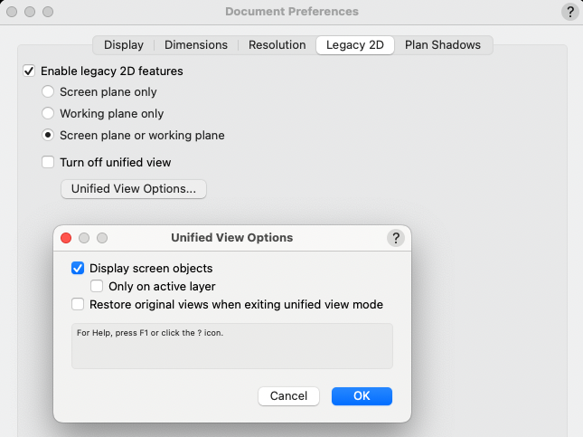
Raymond
-
Hello @Jayme McColgan,
I know less about this than you, but I am using the following line in my ResetEvent:
vs.OLDAddLoadHangPoint(PIOHand, 0, InsP, FALSE);
where InsPt is the PIO insertion point. Unless told otherwise, I believe FALSE declares it as a Point Load, and TRUE declares it as a Distributed Load.
I doubt it will solve what ails you, but it is one more piece to an undefined puzzle.
Any documentation, or usage examples, from the Mother Ship would be immensely appreciated.
Raymond
-
22 hours ago, KingChaos said:
can you pls help with the minimal code is needed for a 3d pathobject? The height ob the object will be the length between the 2 clicks i guess?
18 hours ago, KingChaos said:it will take pages ^^ if i start now for all functions. okay, i see it will take some time.
Hello @KingChaos,
Without knowing more specifically what you want to achieve I can only give a basic response to your question.
What I'm expecting from you is a description that you might give a scripting professional that you hired to do the work as you outline it.
As an example (not reflecting your actual intentions):
1) Draw a 3D Polygon.
2) Use the center of polygon sides to create "extrudes".
3) Use "Depth" field in OIP to set extrude's depth.
4) Use "Extrude" field in OIP to set extrude's height.
5) Have a Button in OIP to save each extrude to a symbol and name it uniquely. (optional)
6) Have a Button in OIP to build Worksheet takeoffs from PIO. (optional)
7) Use Popup menu in OIP to apply Texture(s). (optional)
The more detail you supply about each functional step you want, the better. Knowing how your OIP is supposed to be used to control your object will help us suggest what we would recommend you try.
In a thread from December 2022 I posted a basic outline of the code needed for an Event-Enabled-PIO. This won't solve your problem, but it will show you what the outline of an event-enabled Plug-In might look like. Your specific code would need to be inserted into this shell to make it do anything useful. Here's the link:
Raymond
-
Hello @KingChaos,
To give you an appropriate answer I need to know how your PIO is supposed to work. If you just draw a path and something happens, the PIO is relatively simple. However, if you you want to have controls showing in the OIP, like one or more buttons, checkboxes, radio buttons, popup menus, etc., then you will want an Event-Enabled PIO, and that is not a simple thing to describe.
If you would, please describe how you want the PIO to work – what you will draw, what actions you want perform on the object after it's drawn, etc. The more detail you provide the easier it will be for me (us) to be specific.
Thank you,
Raymond
-
3 hours ago, KingChaos said:
Now i need to know, how i can make a symbol out of it with OIP parameter ports.
Place your PIO in the drawing. Select it. Open menu Modify > Create Symbol..., name your symbol, and check the items circled in red. This creates a RED Symbol, which places a copy of your PIO in the drawing when you place the symbol. Your parameters will show in the OIP.
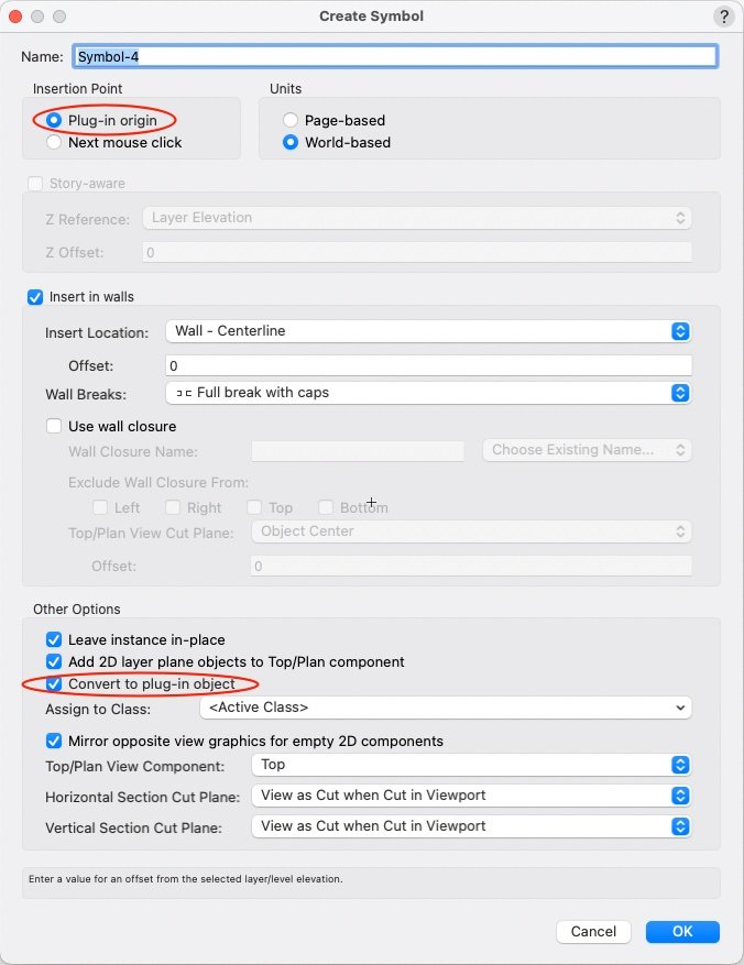
Raymond
-
If I was going to script my solid, I would probably use SubtractSolid() to make a shell. There is also the Shell Solid Tool, if you are drawing manually.
To use SubtractSolid(), create an extruded solid, duplicate it in place, shrink the duplicate (and possibly move it to create an open carcass), then subtract it from the first solid. There are other ways to achieve the same result. You can also extrude the outer sides of the box, 5 or 6 sides, and use AddSolid() to each one sequentially to build up the same solid. You can also extrude the back, then extrude a hollow Polyline for the walls, and use AddSolid() to join them.
If you have further questions on Solid Geometry, check out the SOLIDS MODELING AND 3D PRINTING section in Solids Modeling and Subdivision in this Forum. Everything you want to do can be done. Baby steps will you get there. When you get a routine finished in VS or Python, you'll be amazed how fast it will run.
All the best,
Raymond
-
I forgot to ask, were you able to add the code above to a Point Object PIO? If you need help with that, just ask.
Raymond
-
1
-
-
Well @KingChaos,
You are off to a good start. There are no LARGE steps in programming, only small ones. You will find lots of support in this forum, so don't spend too much time trying to figure out confusing things on your own. Ask and you shall be answered (not to sound too preachy), at least as far as an answer exists.
The Export Script trick is a good one. Use it as needed. Example code, and this forum are your next best tools. With each example you will gain confidence with the power of scripting. It is a natural fit for CAD work. Sometimes Marionette will be all you need, but Vectorscript and Python offer different ways solve the same problems. Each has strengths over the other.
Hope to see you again, soon.
Raymond
-
Hello, @Mike Rock.
Try the following and see how far it gets you. I made some changes, all noted with "***", in your code, but I did not test it in a plug-in.
One significant change involves your line H := FSActLayer;. I replaced FSActLayer, which only works on Drawing Layers, and replaced it with "PIOHand", a handle to the object you're trying to build. "PIOHand" is returned from a call to GetCustomObjectInfo(). See notes in your script where I made edits. Good luck, and write back with your next question.
Oh, I also changed some indentation, and added comments to help read the code. I find is very helpful to comment the END statements to reference what they are ending. This can save LOTS of time when making future edits.
PROCEDURE Example3; CONST kObjOnInitXProperties = 5; kResetEventID = 3; kObjXPropHasUIOverride = 8; kWidgetButton = 12; kObjOnObjectUIButtonHit = 35; buttonID_1 = 1234; {user-definable index} VAR PIOName :STRING; {*** ADD THIS LINE ***} PIOHand, recHand, wallHand :HANDLE; {*** ADD THIS LINE ***} theEvent, theButton :LONGINT; result :BOOLEAN; sourceFieldNumber,dialog1 :INTEGER; buttonEventID, color :INTEGER; displayString :STRING; thisDoesNothing, r, g, b :LONGINT; H :Handle; FUNCTION ColorPopUp :Integer; VAR dialog1, result :INTEGER; PROCEDURE Dialog_Handler(VAR item :LONGINT; data :LONGINT); BEGIN CASE item OF SetupDialogC: BEGIN SetColorChoice(dialog1, 4, 1242); END; { SetupDialogC } 1: BEGIN GetColorChoice(dialog1, 4, result); ColorPopUp := result; END; { 1 } END; { CASE item } END; { Dialog_Handler } BEGIN { ColorPopUp } dialog1 := CreateLayout('Example Dialog', FALSE, 'OK', 'Cancel'); CreateColorPopup(dialog1, 4, 24); SetFirstLayoutItem(dialog1, 4); result := RunLayoutDialog(dialog1, Dialog_Handler); END; { ColorPopUp } BEGIN { MAIN } result := GetCustomObjectInfo(PIOName, PIOHand, recHand, wallHand); {*** ADD THIS LINE ***} vsoGetEventInfo(theEvent, theButton); CASE theEvent OF {User has single-clicked the object's icon.} kObjOnInitXProperties: BEGIN {This tells VW to let the object decide what goes onto the Object Info palette.} result := SetObjPropVS(kObjXPropHasUIOverride, TRUE); {Now we manually add the "normal" parameters...} {One way is to use this single call to add all of the existing parameters.} result := vsoInsertAllParams; {Alternatively, you can use this to tack individual parameters onto the end of the list one at a time. This way, you don't have to use SetParameterVisibility in the reset event to hide parameters that you never want to see.} sourceFieldNumber := 1; displayString := 'My Great Field Name'; result := vsoAppendParamWidget(sourceFieldNumber, displayString, thisDoesNothing); {Finally, we add the button.} displayString := 'Color Select'; result := vsoAppendWidget(kWidgetButton, buttonID_1, displayString, thisDoesNothing); END; { kObjOnInitXProperties } {User has clicked a button in the Object Info palette.} kObjOnObjectUIButtonHit: BEGIN CASE theButton OF buttonID_1: BEGIN color := ColorPopUp; {pops up a color select dialog} {*** remove following line. FSActLayer does not work inside PIOs as expected. ***} { h := FSActLayer; } {selects the rectangle created else where in the script} {*** change H to PIOHand ***} SetClass(PIOHand, 'None'); {If this line is commented out the script doesn't work as intended} ColorIndexToRGB(color, r, g, b); {converts the value from the colorpopup function to RGB} SetFillback(h, r, g, b); {sets the color of the rectangle} RedrawSelection; {refreshes the rectangle to show new color} END; { buttonID_1 } END; { CASE theButton } END; { kObjOnObjectUIButtonHit } {Object reset has been called.} kResetEventID: BEGIN Rect(0, 0, 1, 1); END; { kResetEventID } END; { CASE theEvent } END; { MAIN } RUN(Example3);HTH,
Raymond
-
I've annotated the code you posted to show you what each line does. Then further down I offer you some options for rewriting it that may make it easier to follow.
{Object Creation Code} { this sets the active class – optional } NameClass('Keine'); { the extrusion starts with this statement } BeginXtrd(0,500); { these lines define stroke, fill, and color attributes } PenSize(4); PenPatN(2); FillPat(1); PenFore(0,0,0); PenBack(65535,65535,65535); FillFore(0,0,0); FillBack(65535,65535,65535); { this is the shape to be extruded } RectangleN(0,0,1,0,890,680); { these lines define a drop shadow, which is not used so can be deleted } objectHandle := LNewObj; SetDropShadowData(objectHandle, 0,0.1,0.05,#315d,75,0,0,0); EnableDropShadow(objectHandle, FALSE); { the extrusion ends with this statement } EndXtrd; { *** you need an EndXtrd statement to make it work **** }
To simplify the above code I've rewritten it here, adding comments, spaces, and removing dead code:{ these lines define stroke, fill, and color attributes } { they may be included or excluded as desired } PenSize(4); PenPatN(2); FillPat(1); PenFore(0,0,0); PenBack(65535,65535,65535); FillFore(0,0,0); FillBack(65535,65535,65535); NameClass('Keine'); { set the active class – optional } { these next three lines draw the geometry } BeginXtrd(0,500); { the extrusion starts here } RectangleN(0,0,1,0,890,680); { this is the shape to be extruded } EndXtrd; { the extrusion ends here }Using @Jesse Cogswell's approach, here is another rewrite:
BeginXtrd(0,500); { the extrusion starts here } RectangleN(0,0,1,0,890,680); { this is the shape to be extruded } EndXtrd; { the extrusion ends here } { the following lines are optional, and they only refer to the previously created extrude } SetClass(LNewObj, 'Keine'); { set the object's class } SetLW(LNewObj, 4); { 4 mils wide } SetLSN(LNewObj, 2); { use pen foreground color - solid } SetFPat(LNewObj, 1); { use fill background color - solid } SetFillFore(LNewObj, 0,0,0); { black } SetPenFore(LNewObj, 0,0,0); { black } SetFillBack(LNewObj, 65535,65535,65535);{ white } SetPenBack(LNewObj, 65535,65535,65535); { white }Note the use of LNewObj to reference the previously created object.
Lastly, to make this adaptable to a PIO I added "p" variables where you would want to control your code. Open the Plug-In Editor to start defining your plug-in object. (Cmd-Shift-Z on a Mac, or Ctrl-Shift-Z on a PC.) Click on the NEW... button, give it a name, and select a PIO type. If you start with a Point Object PIO you will need to create three variables. Let's assume you choose the names, Length, Width, and Extrude. These are defined in the Plug-in Editor, under the Parameters tab. Make them type Dimension.
In your script you will refer to these values as PLength, PWidth, and PExtrude, respectively. In your code, these are constants which means you can't change their values. Technically, you can, but it will have no effect on anything when you are done.
The only lines you will need to edit are these:
BeginXtrd(0, PExtrude); { the extrusion starts here } RectangleN(0, 0, 1, 0, PLength, PWidth); { this is the shape to be extruded } EndXtrd; { the extrusion ends here }Now you can paste the code into the PIO Editor, wrapped in the basic Pascal program shell. Add any of the Class, Color, or Pen & Fill commands you think are necessary and you have a simple plugin that has user defined ∆XYZ components. Note – if you assign Color and Class inside your plug-in, you won't be able to change them from the outside.
Here's the minimum code that will draw an extruded box with parameters showing in the OIP:
PROCEDURE xxx; BEGIN BeginXtrd(0, PExtrude); { the extrusion starts here } RectangleN(0, 0, 1, 0, PLength, PWidth); { this is the shape to be extruded } EndXtrd; { the extrusion ends here } END; Run(xxx);Now when your code runs you will be able to change all of its parameters in the OIP.
The very last step is to add your plug-in to you workspace as a TOOL , and you can then place it in your drawing with a click.
HTH,
Raymond
-
2
-
vs.SetParent(), Ressource Folders, 2024
in Python Scripting
Posted
Hi @Letti R,
Of course your folders are nested. Why would life be easy?
The way to get the first folder is to look at everything in the Symbol Library and skip the symbols. Here are two Pascal routines that will return a handle to the First SymFolder. Hopefully you can convert them to Python easily. If not, write back and I can help.
	function FSymFolder :Handle;
	{ Get a handle to the First Symbol Folder in the Symbol Library. }
	{ 19 Apr 2024 - Raymond Mullin }
	Const
		SymFolderType = 92;
	Var
		SymHnd :Handle;
	Begin
		SymHnd := FSymDef;		{ Symbol or Folder }
		if (SymHnd <> nil) then
			while (GetTypeN(SymHnd) <> SymFolderType) do
				SymHnd := NextObj(SymHnd);
		FSymFolder := SymHnd;
	End;		{ FSymFolder }
The same routine using ForEachObjectInList().
	function FSymFolder :Handle;
	{ Return a handle to the First Symbol Folder in the Symbol Library if one exists, otherwise return NIL. }
	{ 19 Apr 2024 - Raymond Mullin }
	Const
		SymFolderType = 92;
	Var
		FldrHnd :Handle;

		function isFolder(H :Handle) :Boolean;
		Begin
			if (GetTypeN(H) = SymFolderType) then
				FldrHnd := H;
			isFolder := FldrHnd <> nil;		{ return True to stop }
		End;		{ isFolder }

	Begin	{ FSymFolder }
		FldrHnd := nil;		{ Folder handle }
		ForEachObjectInList(isFolder, 0, 0, FSymDef);		{ All objects, Shallow }
		FSymFolder := FldrHnd;
	End;		{ FSymFolder }
Finding the Next Symbol Folder is similar to finding the first, but you start looking using a handle to the next object after the first Symbol Folder.
Raymond