


MullinRJ
-
Posts
2,004 -
Joined
-
Last visited
Content Type
Profiles
Forums
Events
Articles
Marionette
Store
Everything posted by MullinRJ
-
2D shapes keep disappearing right after drawing
MullinRJ replied to MGuilfoile's question in Troubleshooting
Hello @MGuilfoile, Like you, I enjoy using the Screen Plane while drawing in 3D. If your problem in not related to the Clip Cube, how do you have your Document Preferences set for Legacy 2D drawing? I use the following settings and enjoy the older style of drawing that used to exist. I don't use Clip Cube, so I cannot comment on its interaction. Please write back and share your findings when you can. Raymond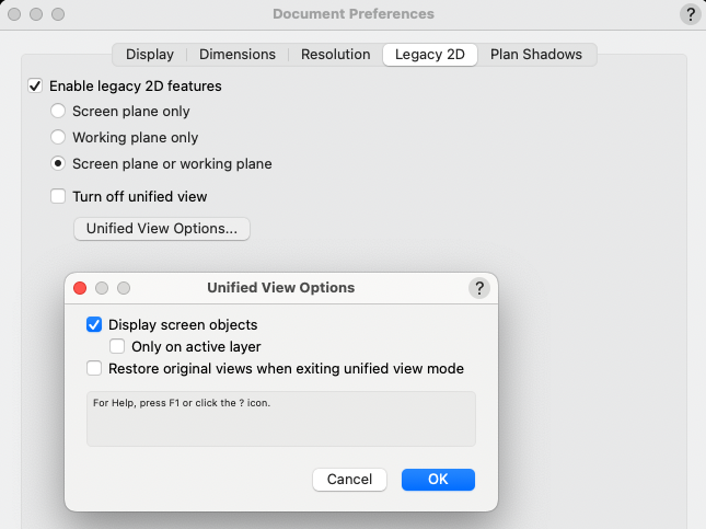
-
Hello @Jayme McColgan, I know less about this than you, but I am using the following line in my ResetEvent: vs.OLDAddLoadHangPoint(PIOHand, 0, InsP, FALSE); where InsPt is the PIO insertion point. Unless told otherwise, I believe FALSE declares it as a Point Load, and TRUE declares it as a Distributed Load. I doubt it will solve what ails you, but it is one more piece to an undefined puzzle. Any documentation, or usage examples, from the Mother Ship would be immensely appreciated. Raymond
-
Hello @KingChaos, Without knowing more specifically what you want to achieve I can only give a basic response to your question. What I'm expecting from you is a description that you might give a scripting professional that you hired to do the work as you outline it. As an example (not reflecting your actual intentions): 1) Draw a 3D Polygon. 2) Use the center of polygon sides to create "extrudes". 3) Use "Depth" field in OIP to set extrude's depth. 4) Use "Extrude" field in OIP to set extrude's height. 5) Have a Button in OIP to save each extrude to a symbol and name it uniquely. (optional) 6) Have a Button in OIP to build Worksheet takeoffs from PIO. (optional) 7) Use Popup menu in OIP to apply Texture(s). (optional) The more detail you supply about each functional step you want, the better. Knowing how your OIP is supposed to be used to control your object will help us suggest what we would recommend you try. In a thread from December 2022 I posted a basic outline of the code needed for an Event-Enabled-PIO. This won't solve your problem, but it will show you what the outline of an event-enabled Plug-In might look like. Your specific code would need to be inserted into this shell to make it do anything useful. Here's the link: https://forum.vectorworks.net/index.php?/topic/103538-event-enabled-plugins-with-variable-number-of-parameters/#comment-452032 Raymond
-
Hello @KingChaos, To give you an appropriate answer I need to know how your PIO is supposed to work. If you just draw a path and something happens, the PIO is relatively simple. However, if you you want to have controls showing in the OIP, like one or more buttons, checkboxes, radio buttons, popup menus, etc., then you will want an Event-Enabled PIO, and that is not a simple thing to describe. If you would, please describe how you want the PIO to work – what you will draw, what actions you want perform on the object after it's drawn, etc. The more detail you provide the easier it will be for me (us) to be specific. Thank you, Raymond
-
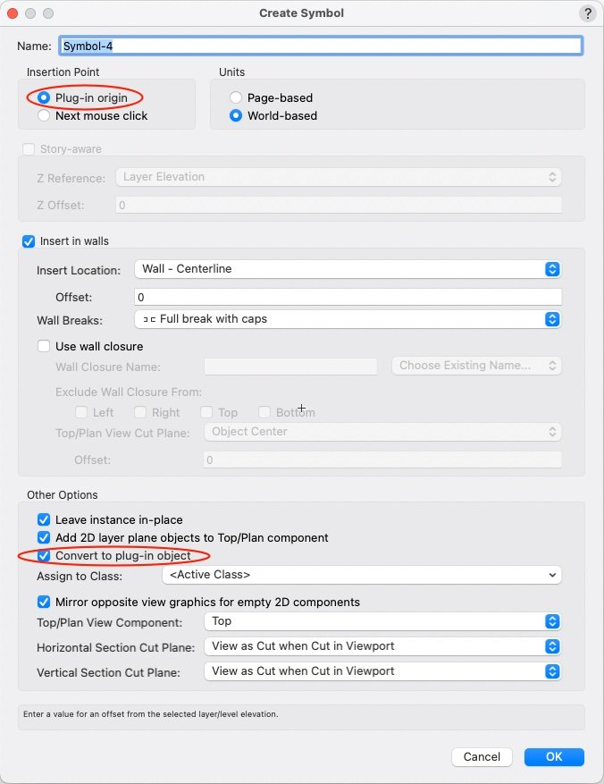
Place your PIO in the drawing. Select it. Open menu Modify > Create Symbol..., name your symbol, and check the items circled in red. This creates a RED Symbol, which places a copy of your PIO in the drawing when you place the symbol. Your parameters will show in the OIP. Raymond Create Symbol Dialog.pdf
-
If I was going to script my solid, I would probably use SubtractSolid() to make a shell. There is also the Shell Solid Tool, if you are drawing manually. To use SubtractSolid(), create an extruded solid, duplicate it in place, shrink the duplicate (and possibly move it to create an open carcass), then subtract it from the first solid. There are other ways to achieve the same result. You can also extrude the outer sides of the box, 5 or 6 sides, and use AddSolid() to each one sequentially to build up the same solid. You can also extrude the back, then extrude a hollow Polyline for the walls, and use AddSolid() to join them. If you have further questions on Solid Geometry, check out the SOLIDS MODELING AND 3D PRINTING section in Solids Modeling and Subdivision in this Forum. Everything you want to do can be done. Baby steps will you get there. When you get a routine finished in VS or Python, you'll be amazed how fast it will run. All the best, Raymond
-
I forgot to ask, were you able to add the code above to a Point Object PIO? If you need help with that, just ask. Raymond
-
Well @KingChaos, You are off to a good start. There are no LARGE steps in programming, only small ones. You will find lots of support in this forum, so don't spend too much time trying to figure out confusing things on your own. Ask and you shall be answered (not to sound too preachy), at least as far as an answer exists. The Export Script trick is a good one. Use it as needed. Example code, and this forum are your next best tools. With each example you will gain confidence with the power of scripting. It is a natural fit for CAD work. Sometimes Marionette will be all you need, but Vectorscript and Python offer different ways solve the same problems. Each has strengths over the other. Hope to see you again, soon. Raymond
-
Hello, @Mike Rock. Try the following and see how far it gets you. I made some changes, all noted with "***", in your code, but I did not test it in a plug-in. One significant change involves your line H := FSActLayer;. I replaced FSActLayer, which only works on Drawing Layers, and replaced it with "PIOHand", a handle to the object you're trying to build. "PIOHand" is returned from a call to GetCustomObjectInfo(). See notes in your script where I made edits. Good luck, and write back with your next question. Oh, I also changed some indentation, and added comments to help read the code. I find is very helpful to comment the END statements to reference what they are ending. This can save LOTS of time when making future edits. PROCEDURE Example3; CONST kObjOnInitXProperties = 5; kResetEventID = 3; kObjXPropHasUIOverride = 8; kWidgetButton = 12; kObjOnObjectUIButtonHit = 35; buttonID_1 = 1234; {user-definable index} VAR PIOName :STRING; {*** ADD THIS LINE ***} PIOHand, recHand, wallHand :HANDLE; {*** ADD THIS LINE ***} theEvent, theButton :LONGINT; result :BOOLEAN; sourceFieldNumber,dialog1 :INTEGER; buttonEventID, color :INTEGER; displayString :STRING; thisDoesNothing, r, g, b :LONGINT; H :Handle; FUNCTION ColorPopUp :Integer; VAR dialog1, result :INTEGER; PROCEDURE Dialog_Handler(VAR item :LONGINT; data :LONGINT); BEGIN CASE item OF SetupDialogC: BEGIN SetColorChoice(dialog1, 4, 1242); END; { SetupDialogC } 1: BEGIN GetColorChoice(dialog1, 4, result); ColorPopUp := result; END; { 1 } END; { CASE item } END; { Dialog_Handler } BEGIN { ColorPopUp } dialog1 := CreateLayout('Example Dialog', FALSE, 'OK', 'Cancel'); CreateColorPopup(dialog1, 4, 24); SetFirstLayoutItem(dialog1, 4); result := RunLayoutDialog(dialog1, Dialog_Handler); END; { ColorPopUp } BEGIN { MAIN } result := GetCustomObjectInfo(PIOName, PIOHand, recHand, wallHand); {*** ADD THIS LINE ***} vsoGetEventInfo(theEvent, theButton); CASE theEvent OF {User has single-clicked the object's icon.} kObjOnInitXProperties: BEGIN {This tells VW to let the object decide what goes onto the Object Info palette.} result := SetObjPropVS(kObjXPropHasUIOverride, TRUE); {Now we manually add the "normal" parameters...} {One way is to use this single call to add all of the existing parameters.} result := vsoInsertAllParams; {Alternatively, you can use this to tack individual parameters onto the end of the list one at a time. This way, you don't have to use SetParameterVisibility in the reset event to hide parameters that you never want to see.} sourceFieldNumber := 1; displayString := 'My Great Field Name'; result := vsoAppendParamWidget(sourceFieldNumber, displayString, thisDoesNothing); {Finally, we add the button.} displayString := 'Color Select'; result := vsoAppendWidget(kWidgetButton, buttonID_1, displayString, thisDoesNothing); END; { kObjOnInitXProperties } {User has clicked a button in the Object Info palette.} kObjOnObjectUIButtonHit: BEGIN CASE theButton OF buttonID_1: BEGIN color := ColorPopUp; {pops up a color select dialog} {*** remove following line. FSActLayer does not work inside PIOs as expected. ***} { h := FSActLayer; } {selects the rectangle created else where in the script} {*** change H to PIOHand ***} SetClass(PIOHand, 'None'); {If this line is commented out the script doesn't work as intended} ColorIndexToRGB(color, r, g, b); {converts the value from the colorpopup function to RGB} SetFillback(h, r, g, b); {sets the color of the rectangle} RedrawSelection; {refreshes the rectangle to show new color} END; { buttonID_1 } END; { CASE theButton } END; { kObjOnObjectUIButtonHit } {Object reset has been called.} kResetEventID: BEGIN Rect(0, 0, 1, 1); END; { kResetEventID } END; { CASE theEvent } END; { MAIN } RUN(Example3); HTH, Raymond
-
@KingChaos I've annotated the code you posted to show you what each line does. Then further down I offer you some options for rewriting it that may make it easier to follow. {Object Creation Code} { this sets the active class – optional } NameClass('Keine'); { the extrusion starts with this statement } BeginXtrd(0,500); { these lines define stroke, fill, and color attributes } PenSize(4); PenPatN(2); FillPat(1); PenFore(0,0,0); PenBack(65535,65535,65535); FillFore(0,0,0); FillBack(65535,65535,65535); { this is the shape to be extruded } RectangleN(0,0,1,0,890,680); { these lines define a drop shadow, which is not used so can be deleted } objectHandle := LNewObj; SetDropShadowData(objectHandle, 0,0.1,0.05,#315d,75,0,0,0); EnableDropShadow(objectHandle, FALSE); { the extrusion ends with this statement } EndXtrd; { *** you need an EndXtrd statement to make it work **** } To simplify the above code I've rewritten it here, adding comments, spaces, and removing dead code: { these lines define stroke, fill, and color attributes } { they may be included or excluded as desired } PenSize(4); PenPatN(2); FillPat(1); PenFore(0,0,0); PenBack(65535,65535,65535); FillFore(0,0,0); FillBack(65535,65535,65535); NameClass('Keine'); { set the active class – optional } { these next three lines draw the geometry } BeginXtrd(0,500); { the extrusion starts here } RectangleN(0,0,1,0,890,680); { this is the shape to be extruded } EndXtrd; { the extrusion ends here } Using @Jesse Cogswell's approach, here is another rewrite: BeginXtrd(0,500); { the extrusion starts here } RectangleN(0,0,1,0,890,680); { this is the shape to be extruded } EndXtrd; { the extrusion ends here } { the following lines are optional, and they only refer to the previously created extrude } SetClass(LNewObj, 'Keine'); { set the object's class } SetLW(LNewObj, 4); { 4 mils wide } SetLSN(LNewObj, 2); { use pen foreground color - solid } SetFPat(LNewObj, 1); { use fill background color - solid } SetFillFore(LNewObj, 0,0,0); { black } SetPenFore(LNewObj, 0,0,0); { black } SetFillBack(LNewObj, 65535,65535,65535);{ white } SetPenBack(LNewObj, 65535,65535,65535); { white } Note the use of LNewObj to reference the previously created object. Lastly, to make this adaptable to a PIO I added "p" variables where you would want to control your code. Open the Plug-In Editor to start defining your plug-in object. (Cmd-Shift-Z on a Mac, or Ctrl-Shift-Z on a PC.) Click on the NEW... button, give it a name, and select a PIO type. If you start with a Point Object PIO you will need to create three variables. Let's assume you choose the names, Length, Width, and Extrude. These are defined in the Plug-in Editor, under the Parameters tab. Make them type Dimension. In your script you will refer to these values as PLength, PWidth, and PExtrude, respectively. In your code, these are constants which means you can't change their values. Technically, you can, but it will have no effect on anything when you are done. The only lines you will need to edit are these: BeginXtrd(0, PExtrude); { the extrusion starts here } RectangleN(0, 0, 1, 0, PLength, PWidth); { this is the shape to be extruded } EndXtrd; { the extrusion ends here } Now you can paste the code into the PIO Editor, wrapped in the basic Pascal program shell. Add any of the Class, Color, or Pen & Fill commands you think are necessary and you have a simple plugin that has user defined ∆XYZ components. Note – if you assign Color and Class inside your plug-in, you won't be able to change them from the outside. Here's the minimum code that will draw an extruded box with parameters showing in the OIP: PROCEDURE xxx; BEGIN BeginXtrd(0, PExtrude); { the extrusion starts here } RectangleN(0, 0, 1, 0, PLength, PWidth); { this is the shape to be extruded } EndXtrd; { the extrusion ends here } END; Run(xxx); Now when your code runs you will be able to change all of its parameters in the OIP. The very last step is to add your plug-in to you workspace as a TOOL , and you can then place it in your drawing with a click. HTH, Raymond
-
Sadly, there is no Macro Recorder in VW. It has been requested many times. For geometry, you can draw shapes in a new file, then use menu File > Export > Export Script.... This will save a VectorScript file to disk. Using a text editor, you can extract the geometry calls to your objects and substitute any or all of the numerical parameters for variables which you can control in your script. This is a shortcut to building a script, but not the same as a Macro Recorder. If you have any questions about this, holler back. Raymond
-
Hello David, I found constants for the Slab Tool (-248) and the Wall End Cap Tool (-355). I did not find constants for the Door or Window tools, but those two can be called with CallToolByName() or SetToolByName(), as Pat mentioned. Raymond
-
In my first post-college job, some 40+ years ago, I chose to learn Pascal over Fortran to complete an assignment. I have never looked back. I am amazed that after all these years I still use Pascal as a productive tool. Pascal is like my favorite pair of jeans – they still fit, so I still wear them. I've learned and used other languages and see their benefits, but Pascal will always be closest to my heart. Thank you Niklaus Wirth. Bon Voyage.
-
vs.AddChoice - continuously adds values to pull down
MullinRJ replied to spettitt's topic in Python Scripting
12255 is "SetupDialogC", and is found in the dialog event loop. It is an event that is passed to your dialog event loop once before the dialog returns any of your events, i.e., before you do anything. This event is where you perform all of your setup actions. There is also 12256 for "SetDownDialogC", which is called once after the dialog returns all of your events, i.e., after you press the OK or Cancel buttons. HTH, Raymond -
Does VS command "GetCurrentPlanarRefID" do anything useful?
MullinRJ replied to MullinRJ's topic in Vectorscript
Hi @BillW, I have tried GetCurrentPlanarRefID with and without objects on a working plane that I just set, and still get no meaningful response from it. I am very familiar with all of the other calls you cited, and they perform exactly as expected when used. I really just want find out how GetCurrentPlanarRefID is supposed to be used and under what conditions it operates. Thank you kindly for your reply, Raymond -
Without breaking out your high school Geometry books, you can use vectors to keep track of where you are and where you want to go. Without knowing where you reference your base part I cannot give you exact code for your problem, but it should look something like this: # rotate 2D vector V by Ang degrees def RotVec(V, Ang): return vs.Ang2Vec(vs.Vec2Ang(V)+Ang, vs.Norm(V)) # add vectors A and B def VecAdd (A, B): return tuple(map(sum, zip(A, B))) # subtract vector B from A def VecSub (A, B): return tuple(map(lambda x, y: x - y, A, B)) ... DispV = VecSub(LRcornerPt, InsertionPt) % displacement vector NextInsPt = VecAdd(InsertionPt, RotVec(DispV, PartRotation)) where PartRotation is vs.GetSymRot(symHd) for symbols, or an angle value you keep track of programmatically; and the vector values are tuples of (X, Y). I have not tested this, so proceed with caution. If you need more help, write back or contact me offline. I'd be more than happy to help. Raymond
-
When I execute GetCurrentPlanarRefID on a design layer it returns "1" if I am drawing on the Layer Plane or any 3D Working Plane I set. If I change to the Screen Plane it returns '0'. Inside a symbol's 2D side it returns "0", and on the 3D side it returns "-1". Inside an Extrude it returns "-1". On a Sheet Layer it returns "0". I understand the Layer Plane is refID = 1, and the Screen Plane is refID = 0, while Working Planes have other integer values for the refID. I cannot get it to recognize any Working Plane I set in a drawing. Am I missing something, or does this command not do anything I can use? The documentation says: "Return the current plane ref ID. This could be any plane: a working plane, screen plane (0), ground plane of a container, or any arbitrary plane." If anyone has been able to use this command to identify planes other than the Screen or Layer planes, I would really like to hear from you. TIA, Raymond
-
Hi Jayme, It may not be the answer you wanted, but it sounds like you are on the right path. Another thing to evaluate, how fast does CopySymbol() work if your reference file is open all the time? I don't know what your system configuration is, but consider opening the reference file when you launch VW and leave it open for the drafting session. If it works, and your system doesn't slow down, it may keep you from splitting the symbol file right now. Just a thought. All the best, Raymond
-
Hello @Jayme McColgan, First question, did you convert your reference file to VW 2024 format? I would expect this to give you the best chance for success. If you have converted it and your code still runs slowly, I would copy some symbols into a much smaller temporary file and try your code again. If it's still slow, then it's not the reference file's size. Perhaps it's a drive, or network problem. Try copying the file to your computer and try again. Does it run faster when the file is local? If pulling symbols from a much smaller file speeds things up significantly, then I would find a way to partition your non-partitionable file into two or more smaller files. Split it alphabetically and you can easily code your symbol calls to address the correct source file using the symbol's name to determine the source file. Of course there are many ways to approach the overall problem. I hope you find one that works well for you. Raymond
-
Hello, @halfcoupler. Your script seems to work in VW 2024, and 2023. If only one object is selected the OIP updates. If multiple objects are selected, then, yes, the OIP does not update the Class popup menu and displays the old setting. If you have multiple objects selected, do you want to apply the new class name to all of the selected objects? If so, try this script: PROCEDURE Set_A_Class; { Change the class name of all selected objects that are on editable layers. } CONST kNewClass = 'MyClass-Pink_Flamingo'; function ApplyClass(H :Handle) :Boolean; Begin SetClass(H, kNewClass); SetSelect(H); { Resets OIP } End; BEGIN ForEachObjectInLayer(ApplyClass, 3, 0, 4); { Visible/Selected, Shallow, Editable } SysBeep; { make noise when done } END; RUN(Set_A_Class); To assign other class names, change the constant "kNewClass". The ForeEachObjectInLayer() function loops through every object that meets the conditions specified by the three numbers shown in the call. In this case it looks for Visible and Selected objects (1+2), does not go inside Groups or other containers, or Shallow (0), and works across Editable Layers (4). If you need more information on this and similar ForEachObject functions, check out the Developer Wiki and Function Reference Links in the blue bar shown at the top of this page. HTH, Raymond
-
Resource Manager - Action Button - Pop up menu visibility issue
MullinRJ replied to kdenham's question in Troubleshooting
@Pat Stanford, It's this button: I didn't know either until I floated the cursor across the icons looking for a clue. Luckily one popped up. Raymond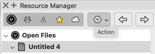
-
Get a dimension's length in document unit precision
MullinRJ replied to Juliensv's topic in Vectorscript
@Juliensv, Are you wanting the value to use in a worksheet, or just in a script? For accessing the length in a script, here's an example that shows the exact length in document units but w/o the units string displayed. PROCEDURE xxx; { Show the length of a selected dimension object. } { 10 Nov 2023 - Raymond J Mullin } VAR H :Handle; B :Boolean; P1, P2 :Vector; BEGIN H := FSActLayer; if (GetTypeN(H) = 63) then begin { Dimension object } B := GetObjectVariablePoint(H, 13, P1.x, P1.y, P1.z); { point 1 } B := GetObjectVariablePoint(H, 14, P2.x, P2.y, P2.z); { point 2 } AlrtDialog(concat('Dimension Length = ', Norm(P2-P1))); { display length } end { if } else AlrtDialog('Selected object is not a DIMENSION object.'); END; Run(xxx); If you want to control the number of decimals displayed in the answer, use the Num2Str() function around the Norm() function, or if you want the answer formatted using the current document units, use the Num2StrF() function. Lastly, if you want the answer for use in a Worksheet function, a some lines will need to be added and removed. HTH, Raymond -
Hello Peter, Reshaper will let you set the 3D view relative to the selected 3D Object. Top, Front, Left, Iso views top and bottom. And you can rotate the view around the primary axes relative to your current view. I believe you have a copy of Reshaper. Let me know if it needs updating. Raymond
-
Also, FWIW, Entered in Group which is also listed as 6756 might be 6755 as defined on the next line: varGetEnteredGroupHandle = 6755, // Handle read - Get the Handle of the current opened for edit group in VW document. BUT, is it? I have not used this pref yet, so I can't tell you exactly how it's supposed to work, but it looks like GetPref(6755) returns returns FALSE if you are on a Design or Sheet Layer, and TRUE if you are inside a GROUP, a Symbol, a Polyline Profile, an Extrude, i.e., inside a container object – BUT – if you enter a GROUP that's inside a Symbol Definition, it returns FALSE. Not sure I understand this last part. And here if gets weirder, if you are inside a Group inside another Group inside a Symbol Def, it returns TRUE. It's Alice Through the Looking Glass trying to find Waldo. This is all off the cuff, and doesn't answer anybody's question at the moment, so enjoy the rabbit hole, all ye who enter. Raymond
-
7013 - Try it, you'll like it 😉

