


CharlesD
-
Posts
55 -
Joined
-
Last visited
Content Type
Profiles
Forums
Events
Articles
Marionette
Store
Posts posted by CharlesD
-
-
Hello All-
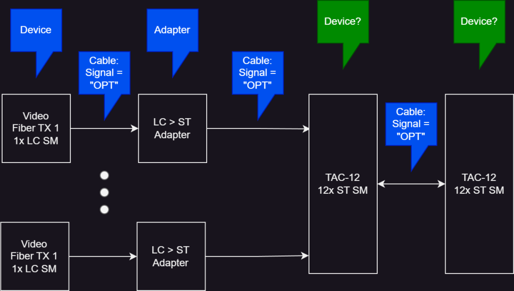
I've stepped away from the world of ConnectCAD for a bit, and I've seem to have forgotten the best way to model fiber cables with multiple connections on it.
In the attached image-- would the two sides of my fiber cable be a different device? How would I model this appropriately?Thanks!
-
Many thanks for these tips, I've been out of the VW Worksheet game for the better part of a decade! It does indeed work well.
I wonder if it would possible to add this type of workflow to the manual or video training somewhere? I think it'd be helpful for others!
-
 1
1
-
-
Fair enough, sounds good!
-
I never really dug into reports before. I am looking for the right way of getting a quantity of of devices and adapters I have in my schematic.
I can't seem to figure out what report I should be using.
It looks like the Parts report makes most sense, however I see a worksheet row for every device or adapter on the drawing.
Which report should I be using?
Thanks!
-
I am curious if any other users are using records + labels for adapters?
I am using adapters to represent modular cards. One thing I've found is that without a label on it it's a little hard for people who not familiar with the specific equipment to understand what the adapter is. I'd love to see a Make_Model (i.e. Description) field or some type of label on the adapter object. Ideally it would have a Label Legend.
Otherwise, the adapter as card workflow feels like a good step forward.
(cc @alexmootv, since you've been playing around with the same stuff)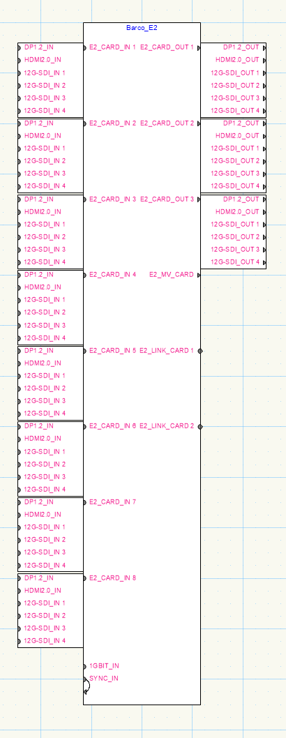
-
@Nikolay ZhelyazkovI do not agree with your assessment.
In that example screenshot at the top of this thread I had to make Single Connect circuit, which I made by making a connection from "OUT 16" to "SFP+" then I dragged the circuit over to "SFP+ 1"-- so I am positive I was in Single Connect mode when this bug occurred.
-
Hi @Nikolay Zhelyazkov-
I was trying to do this with the Connect tool. However, after closing and relaunching the software the bug does not appear again. If I can reproduce this I will bump the thread. Thanks!
-
I was trying to do this with the Connect tool. However, after closing and relaunching the software the bug does not appear again. If I can reproduce this I will bump the thread. Thanks!
-
I have a workflow blocker with what I feel is an arbitrary constraint. I am trying to loop a circuit from an output to an input on the same device, however when attempting to make the connection an error "Same source and destination Device" is presented.
There are a few use cases where I would want this, they mostly revolve around self cascading multi-viewers. After a few minutes thought I cannot determine why this limitation exists, it feels arbitrary. Is this one that could get marked for improvement? Or, does anyone have any tips for me? Thanks! -
I have run into what I am going to classify as a bug, but maybe be an intended behavior. I have some devices where the IO socket is most logical to connect on the left hand side of the device. However it looks like the Connect tool cannot start a circuit from the left side of a device. The error "No outgoing Sockets to connect from." is displayed. This feels like an arbitrary constraint. I may have a workaround, but I do not find it elegant. Does anyone have any tips for me? Thank you!
EDIT: To be clear, the screenshot is what I want to be able to do, but ConnectCAD will not allow me to do.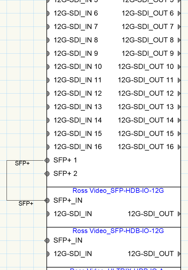
-
Thanks for your input guys, much appreciated!
On the subject of row highlights in yellow: Instead of highlighting the whole row, you can also just highlight the Check column cell that CC auto generates. i.e. don't ever mess with user data, only change colors on CC cells. The counter argument is it (potentially) reduces scan-ability to not have the whole row highlighted. Personally, I don't think it's a huge problem for scan-ability. Furthermore, the highlighting is not too smart to begin with. In the example of the error for "Missing Make"-- why have CC highlight the entire row? If it knows the problem is missing Make field, why not just highlight the field that requires user action?
-
A few things jump out at me as sticking points for this workflow:
Documentation on worksheet
First the small issue: As I've dug into this, I think there is no situation where a user would want to create devices from a CC auto generated worksheet report (i.e. All Layers Device Report. Let me know if I am incorrect. Assuming I am correct, I think users who come to VWX strictly for CC will have a learning curve with this, and it's not immediately apparent. There should be one or two sentences added to this page of the help files that more explicitly tells users that they should be updating this from a custom worksheet they make, or a CC "List".
Symbol selected on creation
Right now if I customize the visual look of a device in CC and hit "Save Device..." it creates a symbol inside of the project file. However when running "Create devices from a worksheet" the device that is created is based on the active settings for the Device Builder tool. If I have an instance of the customized device on my schematic already I can transfer device properties using the Device Tool > Pickup / Apply Attributes commands. These feels like an unnecessary step to me. If my project contains only one instance of a symbol for a device, then the "Creating Devices from Worksheet..." command should apply that symbol to the device without me having to transfer attributes.
Error Checking
When running "Creating Devices from Worksheet..." on a worksheet that has an error, the check field is populated and the cell is highlighted in yellow. If you fix the error (ex. missing Make) and re-run "Creating Devices from Worksheet..." on that worksheet the Check field is nulled, however the cell background color remains yellow. I would prefer that this is restored to its previous color.
Device Mapping
I am assuming this is a bug, but when I accept a Device Mapping suggestion for an inaccurate worksheet (in this case, missing Make) the selected device is not added to the schematic, and the row receives an error in the Check field as skipped. This seems like it should not work this way?
Command completion
When running "Creating Devices from Worksheet..." on a valid worksheet the command completes without intervention by the user. Any newly created devices are inserted into the schematic and selected. This is slick, it allows me to know where and how many devices were added. However, if you run "Creating Devices from Worksheet..." on a worksheet and all those devices are already present in the schematic, the user receives zero indication of what happened. The command just finishes. This could be improved by displaying a pop up like "All devices already present on this layer, there was nothing to add." or something like that. -
Today I RTFM from cover to cover. One question came up for me when I read the section on Building a device.
The help files say:
QuoteCustom devices created with the device builder are automatically saved as symbol definitions in the user folder.
I cannot find these symbols anywhere in the User folder. I note the following:
- A symbol definition is created in the current project. (Sorry if that terminology is wrong, I put VWX down for a few years)
- The Device is added to the User folder in the user's CC DB (ConnectCAD Devices DB.txt)
Can anyone point me towards where the symbol definition is stored in the user folder?
-
@Conrad Preen @Nikolay Zhelyazkov
Is creating a device from device builder the only way to get it stored into the User DB?
I have found Device Builder UI/UX too painful to work quickly. When making small edits to a device that is similar to an existing one I would rather edit it on the design layer. Is it possible to save this instance to the User DB? (Aside from editing the CSV?)
-
1
-
-
I would love it if I could either manually, or fixed Alphanumeric sort the contents of the User Folder items (Signals, Connectors, etc)
Is this a hard technical limitation?
-
2 hours ago, Conrad Preen said:
@CharlesD One first and very important point. In ConnectCAD the connector is always the one that goes on the cable. This circumvents the need for a mapping of which sex of connector mates with what. The only area where we have to talk about chassis connectors at all is in custom connector panels. And there we make a crude transformation of simply deleting the M and replacing with F and vice versa. This simplistic approach has got us through 20+ years.
And it has the merit that ConnectCAD doesn't have to "know" much about connectors. In the cases of DVI and HDMI the standards for these protocols specify the sex of chassis and cable connectors most of the time which is why we haven't add male and female versions. But here's the beauty of it. If you are missing particular type or sex of connector, just add a code of your own.
Best regards
Conrad
Thanks for this advice Conrad!
I do not understand what you mean with the crude transformation. Are you able to explain this concept in more detail? -
I am interested how other users handle connector gender in your drawings?
I noticed in the default CC connectors list it sometimes lists cables with gender, (i.e. XLR3F / XLR3M) and sometimes does not (DVI, HDMI).
Is there a logic to this that I am missing?
-
Bug: Renumbering sockets deletes trailing space
Does anyone have a workaround for this issue? Thanks! -
I am trying to understand the logic behind why you cannot delete many of the default ConnectCAD things. Many feel like they were created with too narrow a scope to be useful in my line of work, and with an inconsistent logic.
For example: CC defaults with "3G" RF and "4G" RF signals-- but it only comes with "HDMI" signal. "HDMI" isn't useful if you have to differentiate between HDMI 1.4, HDMI 2.0, and HDMI 2.1. Three different signal standards that share one connector.
I'd rather just delete it all and make my own. -
Who maintains the database for Device Builder?
I'd like to contribute to it by cleaning up a few of the products I am most familiar with.
-
1
-
-
So there's two places to handle this:
1- In the system drawing
2- In the rack elevationThe current way to handle this in the system drawing is to make a socket that is "Expansion Slot #1" through whatever you need, and create another device which is the expansion card, put it in the drawing, and put your i/o sockets on that expansion card.
@ChollyO I did not consider what you did there with making a "receptacle" for the card on the system drawing. Very slick! That's a nice touch.
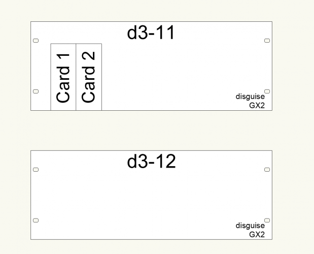
At least for my use case-- the bigger issue is how it appears on the rack elevation. All the way back in my initial posts you can see what I'm asking for: the ability to dock these modular cards into the rack elevation, sort of like you can with "card cages".This has been the one feature that has prevented me from buying ConnectCAD for the last several years.
-
1
-
-
9 hours ago, tspilman said:
Hi there, I've recently picked up connectCAD on VW2022 and have a similar question about network switches;
the Luminex Gigacore 16XT includes 12 x Ethercon connectors (not modules) and 4x (removable) SFP cages - any SFP module can be used, but I tend to only use LC or RJ45.
I would like to be able to specify which type of SFP is used and have the drawing behave accordingly (and I would like it to show up as an item in an equipment list.)
If I use LC cages, I would use multiples of 2 (as I use quad core fibre). If I use RJ45, these are just for more patch outputs on the back of the unit.This means there are not so many combinations out cages, so I *could* pre-build some of these more easily than Conrad above. That said, I do not know how to relate that to the equipment list.
Is it possible to tie all this together so it works nicely (and I can simply create a new SFP module if I were to need a different one in the future?
Sorry if I haven't explained any of this properly; if anyone needs clarification, please let me know.
T
Link to the product page for reference:
I spent a fair amount of time talk with sales / support reps about this.
The short answer is: no. You cannot do this in an elegant way where it also shows up in the rack elevations.
-
@Conrad Preen a few follow ups here:
1- Thanks for the clarification. Devices = Schematic. Equipment Item = Rack Elevation / Layout
2- Can you please elaborate on a suggestion for how to "group these so they are easy to move around"? Are you referring to the way they are represented on the schematic? Or something else?
3- I think it's possible that part of my problem is the way CC operates on equipment items. Is it not possible to treat equipment items like a symbol wherein if I make a change to the visual appearance of all of them?
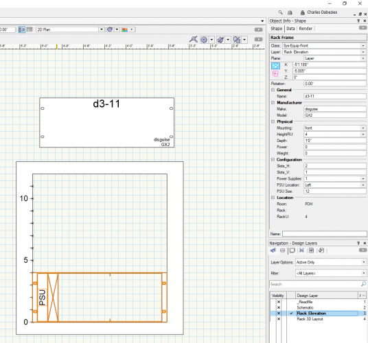
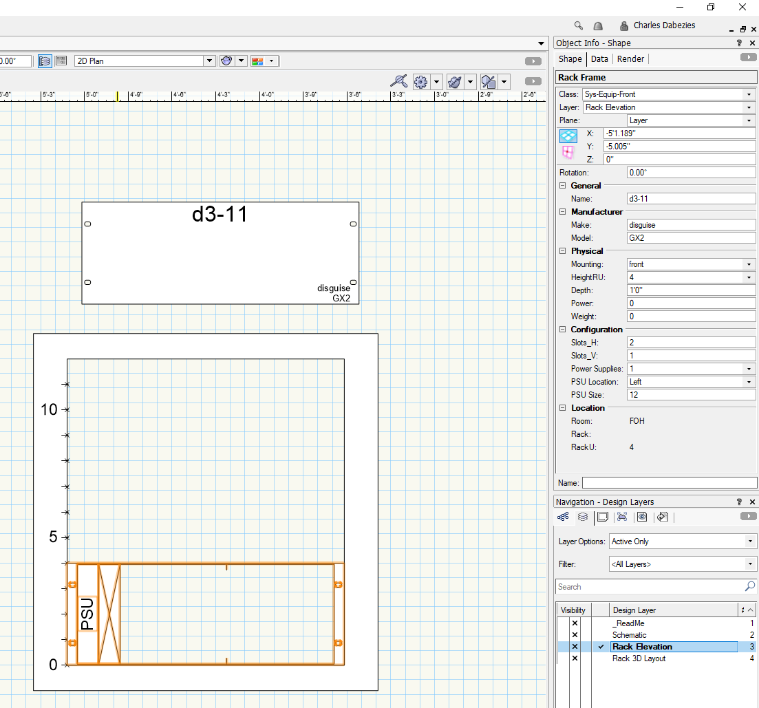
4- Most of my projects get built off of the rack elevations, so I'd like to be able to control the look of devices very carefully on the rack elevation. I would rather the ability to place a "card slot" object into a device and have it accept modular devices, in the way that a rack frame does. Take a look at the attached image. That is my goal.
5- Does CC do any of its counting based on the 2d or 3d equipment layouts? Or are those strictly visual? I was worried I was going to end up with extraneous "rack frame" devices on reports. Additionally I wanted to be able to generate a "configuration" report. So it would be a list of all selected devices with what modular devices are assigned to them.
-
Hi All-
I am new to ConnectCAD and struggling to understand the best workflow for devices with modular cards.
Examples are the Barco E2 and disguise VX4. Both of these devices have slots for modular input/output cards. As far as I can tell in ConnectCAD I have two options:
1- Maintain an instance of the device with every possible card combination.
2- Create a device, but do not put in a rack. Create a "Rack Frame" with the same device name, and put my modular cards into that frame?
My opinion is:
1- Is extremely clunky to manage so many possible permutations. So that's out.
2- Is also very clunky. It doesn't give me a while to decide how my equipment looks in the rack elevation.
I guess I'm looking to be able to make a device that is behaves like a rack frame, where it is has a couple slots for modular cards to insert into. Is this workflow possible?


Modeling Fiber Cables
in ConnectCAD
Posted
Thanks @Conrad Preen! I was afraid this might be the case. The custom adapter, that comprises two logical adapters, certainly works for other use cases-- but I'm afraid it's pretty cumbersome for this workflow.
My last project includes a TAC-24 fiber... with various fiber TX/RX-- in all, we hit many CC adapter objects. We had some SC, some LC, some ST, some SFP, some SFP+, some FiDo SFP, etc.
Combining so many logically separate pieces of kit into one monolithic adapter can't be the best solution to this. Especially when, as a user, I want inventory control / equipment list of all of these pieces. I think we may have had this conversation last year-- but what is the counter argument for not allowing chained adapters?