


Samuel Derenboim
-
Posts
472 -
Joined
-
Last visited
Content Type
Profiles
Forums
Events
Articles
Marionette
Store
Posts posted by Samuel Derenboim
-
-
I understand what you mean now. I've tried using the beam tool, but that's not easily modifiable in terms of depth. The slab tool has to be modified independently from levels in order to adjust its thickness as well. The only other thing i haven't tried would be to use geometry and tie its thickness / width / height to a tag. Not exactly the same thing, but maybe a close second? 🙂
Also, its important to note - the would only be one component in a slab tool that would be able to change in thickness, otherwise the tool would break...It wouldn't know how to distribute the thicknesses for multiple components.
-
My understanding is that there are some components in a slab that would be relative to levels, others to be proprietary like the wall type below. Some are relative to levels, others to the slab. With a wall however, the thicknesses of components never change. Only their depth does - which isn't really called out on schedules.
But what about slabs? When called out on a schedule and a component has different thicknesses, you would have the same slab type appear multiple times on a worksheet if it is to be summarized - however you cannot change any other parametric information like description, additives, etc... to it. This feature would mostly be limited to footings and step foundations, which would definitely be a time saver for sure - but there are are other tools that can do just the same without having to use the slab tool for structural elements.
(of course this is an assumption on my part, is this what you would use it for?)
-
 1
1
-
-
Wouldn't that cause a problem with getting the parametric information to be consolidated for thicknesses in worksheets? otherwise a pretty nice idea
-
1
-
-
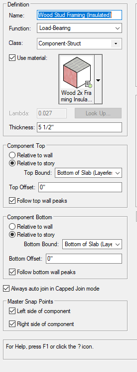
Currently, when doing wall details for wall type components there are portions of a wall that need some extra graphic representation in order to differentiate all other wood stud wall types (i.e. ones with batt insulation, continuous insulation, etc..) or even a sound attenuation blanket. Sometimes the user needs to add extra information to the 'centerline' of a component. Currently, only each edge of a component can have a line type - right pen and left pen. This post is asking for a 'centerline' pen. The reason therebeing is because all other methods have severe limitations to workflow. Let me explain.
Other options that are available are - Use specific hatches and / or use a tile. Granted, Tiling is a very useful function when working only with vectorworks. however, when sharing sections plans or elevations with consultants - tiles are converted to bitmaps which makes them useless in other programs. Therefore its use is unfortunately ruled out if working with consultants.
There is also the use of different hatches representing different components. However, hatches are very difficult to create from scratch, and sometimes even imported hatch tiles that are complex (like batt insulation) or cumbersome. That is why the solution above comes to mind.
Using a linetype is exportable, stable, and very easy to create with using a single backdrop for a core component material. Therefore, I thought of using a linetype as shown below:
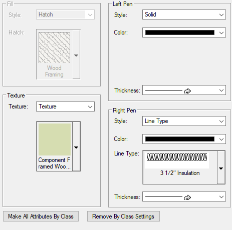
This however caused a problem when doing sections. If the component is 'flipped' - the right side can appear to be on the left side, and therefore it flips the linetype as shown below.
The same thing can be done for slab components and roof components because the problem essentially is the same. Using linetypes in the centerline of a 'slab' component would be that much easier to represent. centerline of components even when flipped would generate a seamless linetype regardless of the side it is cut. Hence the request.
Let me know what you think !
-
It appears this function doesn't existing in VW2022?
Do you think Marionette could help in this regard?
-
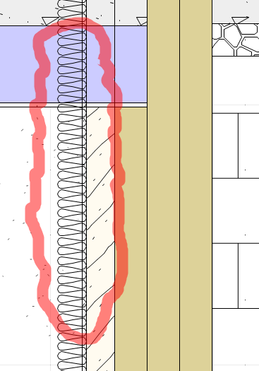
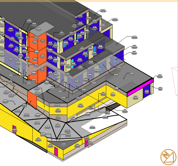
Currently the select connected command can select connected objects that are not closed. What about specific 3d geometry that cannot be custom selected by texture or by hand. Can adjacent connecting objects be selected ? Here is an example image. Let's say I just wanted to select the connected geometry of the object circled in yellow. Is this possible? All geometric objects are not grouped.
-
1
-
-
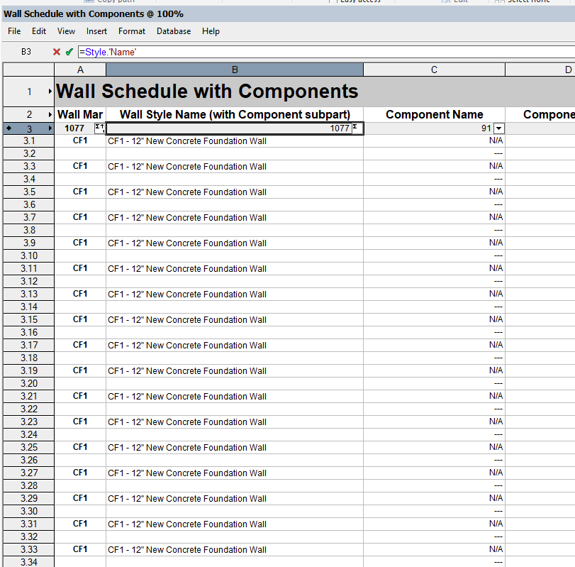
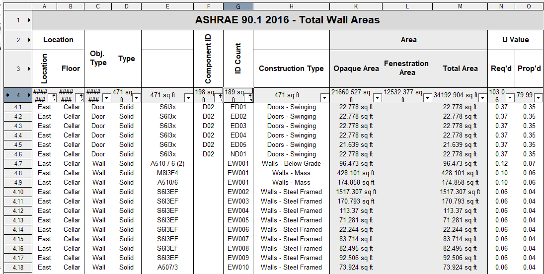
I am trying to summarize in a compact wall schedule the components of a wall and its respective components by the sum method. However, regardless of what I do, I cannot summarize the information. If i have close to 1000 walls of a limited number of styles, why can't the worksheet summarize the areas for those components by wall type rather than list every single component? Or Is there a way to summarize component information?
Thanks in advance!
-
Update 4
All parameters functioning properly except 1 element -
How does one reset count when a condition ends?
I.E. If S3 changes then N1 = 1
Procedure NumberThem;
CONST Rec='!CDA-EnergyTabular';
Fld='ID_Count';
typ='Obj.Type';
dir='Orientation';
VAR H1, layhand: Handle;
N1,N2: Integer;
S1,S2,S3,S4,layName: String;
Procedure Execute(Hd1:Handle);BEGIN
layhand:= GetLayer(hd1);
layName := GetLName(layHand);
S2:= GetRField(Hd1,Rec,typ);
S4:= GetRField(Hd1,Rec,dir);If layName='Cellar Areas' then S3:='0';
If layName='1st Fl. Areas' then S3:='1';
If layName='2nd Fl. Areas' then S3:='2';
If layName='3rd Fl. Areas' then S3:='3';
If layName='4th Fl. Areas' then S3:='4';
If layName='5th Fl. Areas' then S3:='5';
If layName='Roof Areas' then S3:='+';
If S2='Door' then S2:='D';
If S2='Window' then S2:='W';
If S2=' Wall' then S2:='P';
If S2='Cwall' then S2:='CW';
If S2='Slab' then S2:='SL';
If S2='Roof' then S2:='RF';
If S4= 'East' then S4:='E';
If S4= 'West' then S4:='W';
If S4= 'North' then S4:='N';
If S4= 'South' then S4:='S';
If S4= 'Horizontal' then S4:='H';
S1:=Concat(S4,S2,S3,N1);
SetRField(Hd1, Rec, Fld, S1);
N1:=N1+1;
End;BEGIN
N1:=1;
ForEachObject(Execute, ((R IN [Rec])));
End;Run(NumberThem);
-
Update 3 :
Got Layers working. How do I add leading zeros?
Procedure NumberThem;
CONST Rec='Test';
Fld='ID';
typ='Type';
VAR H1, layhand: Handle;
N1: Integer;
S1,S2,S3,layName: String;
Procedure Execute(Hd1:Handle);BEGIN
layhand:= GetLayer(hd1);
layName := GetLName(layHand);
S2:= GetRField(Hd1,Rec,typ);
If layName='cellar' then S3:='0';
If layName='1st floor' then S3:='1';
If S2='Door' then S2:='D';
If S2='Window' then S2:='W';
If S2='Wall' then S2:='P';
If S2='Curtainwall' then S2:='CW';
S1:=Concat(S2,S3,N1);
SetRField(Hd1, Rec, Fld, S1);
N1:=N1+1;
End;BEGIN
N1:=1;
ForEachObject(Execute, ((R IN [Rec])));
End;Run(NumberThem);
-
update 2:
For some reason GetLName(HD1) not working - but the script compiles. My understanding is - it's supposed to get the layer name and then convert it to a string to See if it equates to S3 right? or does it need a separate handle?
Procedure NumberThem;
CONST
Rec='Test';
Fld='ID';
typ='Type';
VARH1: Handle;
N1: Integer;
S1,S2,S3: String;
Procedure Execute(Hd1:Handle);BEGIN
S2:= GetRField(Hd1,Rec,typ);
If S2='Door' then S2:='D';
If S2='Window' then S2:='W';
If S2='Wall' then S2:='P';
If S2='Curtainwall' then S2:='CW';
If GetLName(Hd1)='cellar' then S3:='0';
If GetLName(Hd1)='1st floor' then S3:='1';S1:=Concat(S3,S2,N1);
SetRField(Hd1, Rec, Fld, S1);
N1:=N1+1;
End;BEGIN
N1:=1;
ForEachObject(Execute, ((R IN [Rec])));
End;Run(NumberThem);
-
@Pat Stanford Awesome! Thank you for the hint.
For some reason I thought the field needed to be an integer so I assigned it as such, and it kept getting an error, until i switched it to text - at which point it worked out beautifully.
Regarding the Pseudocode 🙂
The property that describes the object as 'window' 'door' 'curtainwall' 'wall' is located in another field called 'type'
My question:
How does GetName(GetParametricRecord(hd1) know to look into the record called 'type' in order to do : If GetName(GetParametricRecord(Hd1))='Door' then S2:='D';
Do i specify an additional constant for type?
******PROGRESS BELOW***********
Procedure NumberThem;
CONST Rec='Test';
Fld='ID';
typ='Type';
VAR H1: Handle;
N1: Integer;
S1,S2: String;
Procedure Execute(Hd1:Handle);
BEGIN
S2:= GetRField(hd1,Rec,typ);
If S2='Door' then S2:='D';
If S2='Window' then S2:='W';
If S2='Wall' then S2:='P';
If S2='Curtainwall' then S2:='CW';S1:=Concat(S2,N1);
SetRField(Hd1, Rec, Fld, S1);
N1:=N1+1;
End;BEGIN
N1:=1;
ForEachObject(Execute, ((R IN [Rec])));
End;Run(NumberThem);
-
@Pat Stanford thank you again for your consideration !
Let me clarify some of the questions you asked about in both posts
QuoteSo are you going to manually attach the record to the objects you want and delete it from the objects you don't want?
The intention was to rewrite the information in the ID's if the amount of objects increased or decreased, so it would be easier to over-write or 'clear' the original contents of the ID field. This is why I thought the first process needs to 'clear' the ID Fields that way it 're'finds the closest object to the origin, and rewrites to all objects in the document. Looking at the code, the conditional statement this would only be done if the fields were :
IDcount:=1;
B2:=False;
While B2 = False do
Begin
TrackObjectN(0, CallBack, H1, X1,Y1);
If H1 <> Nil then
Begin
SetName(ID_Handle,Num2Str(0,IDcount));
IDcount:=IDcount+1;Looked like it only did the operation if H1 was nil, so i figured by the same logic this script had to work in a similar way. If that was the case, the contents would be cleared, the conditional statement would 're' find all objects with records that have that handle set to nil and the apply the conditions of redoing the ID's for every object again. Sorry if It didn't make sense in my earlier post! Newbie here!
QuoteYour initial worksheet above shows not only a sequential number, but also some kind of code (ED, ND, NW). Do you need that? Or is that just stored separately and concattinated in the data tag?
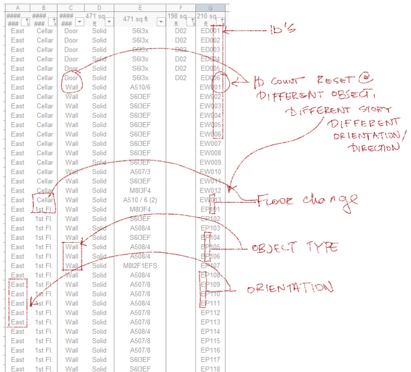
The version that is displayed above is a combination of conditions that make each object unique. You're right in saying that these conditions vary based on
1. Direction (East, West, South, North)
2. Object Type (D=Door, W=Window, P=Partition / Wall, CW= Curtainwall
3. Every floor has a unique leading number. I.E. Cellar = 0, 1st Floor=1, 2nd Floor=2
4. Every Object ID Gets reset when it meets a different object, and object ID's have double digits for the purposes of quantity
i.e. = the 1st door on the North Face on the 2nd floor could be indicated as DN101
For the purposes of the questions I wanted to start simple - with only counting the objects. Since datatags and worksheets can concatenate information, I figured I wouldn't make the script too complicated. In this case, we can just simply do the ID's = which are dual decimal numbers, that way there can be more objects than 10 on a face per floor. All i need to do is reset count as soon as a different object is engage.
I.E. - Let's say I reach number 5 on walls, the count would be reset on a door which would be ND001 instead of ND006 (based on the original count). If it is too complex, we i can work with just a simple count for now.
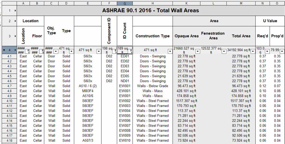
Here is a breakdown of the worksheet. Note that i wasn't consistent in my use of the object type in my worksheet cells...I used W to represent walls until I ran into Windows, after which I used P to represent walls/partitions and W to represent windows. The error here is already mine!
 Quote
QuoteDo you really want/care about the order of the numbering? You specify that you want 1 to be the object closest to the origin, but what do you want after that? To "serial" out from the origin? Do you prefer 2D or 3D?
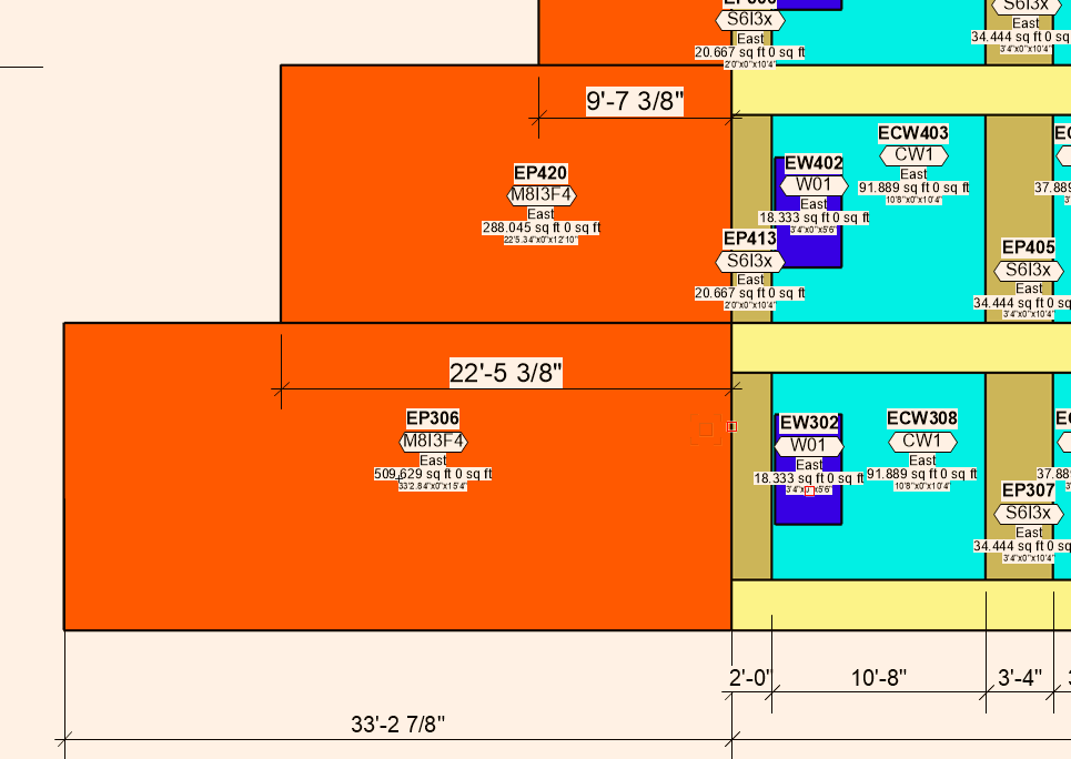
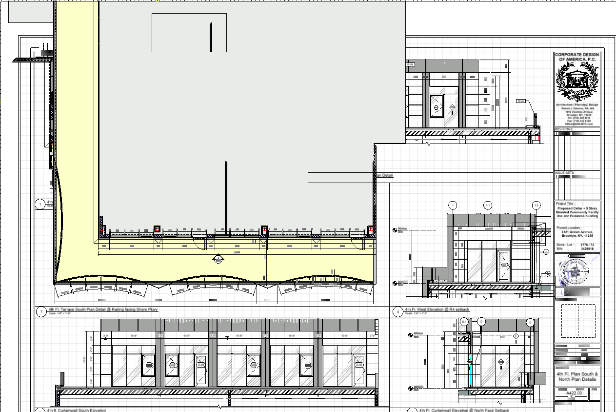
Generally The objects are in 3d like so :
But the Diagrams can be viewed in 2d and in 3d. It isn't really important how we get the Id's, so long as it starts counting from somewhere, and each ID is unique / sequential. It is for the plan examiner to cross reference the graphical drawing with the worksheet - for that particular object / condition.
QuoteYour sample worksheet shows the ID numbers with leading zeros, and different numbers of leading zeros. How do you want the decision on the number of IDs (and therefore the left zero padding) to be done?
Leading 0 is just the level. In reality the ID is just a 2 digit number
 Quote
QuoteI copied and pasted the script above into a blank document. I drew some rectangles and ran the script. When I clicked on the rectangles it named them with a sequential number. When I held down the Command key (Mac, probably Alt of Ctrl on Win), the dialog box to enter the name opened.
Oh wow, I didn't know ctrl activated the popup, Now that conditional statement is understandable!
Just to get on the same page :
If Command then N1:=IntDialog('Enter Number for this Object.', Num2Str(0,N1)); <= the command function activates the use of apple and CTRL for the keyboard, is this correct?
Question 2: what is the purpose of using the TrackObjectN Function?
TrackObjectN(0, CallBack, H1, X1,Y1,Z1);
***update*** - Is this function used to click on the object? (starting to get the feeling that's the click here operation)
Question 3: Why did you use a boolean condition here?
B1, B2: Boolean;....and why are there two booleans? only one is being called out later on. maybe I don't see it, but is B1 Boolean inherently used somewhere to represent N1 in your script?
QuoteBegin
N1:=1;
B2:=False;
While B2 = False doSorry for the long winded explanation! Grateful for your insight into the matter!!!!
-
Please don't laugh, I made a rough outline of the procedure for the franken-script. Can you please tell me if i'm off, how far i am off, and should i even bother? 😂
Procedure SetObjectID;
Var
IDhand: Handle;
X1,Y1, X2,Y2: Real;
IDcount: Integer;
B1,B2: Boolean;Procedure GetIDcount(idhand:handle)
Begin {ID Count Procedure}
1 delete all object id's with (this record,this field) {this resets all id's for the Record/ID so that procedure below can begin}
2 pick object closest to origin, set (this field, this record) closest to 0 @ X, Y, or Z in model space
or object closest to origin x,y on screen3 Set (Record, ID) to 1 from picked object
4 {if any objects that have id = 1 while all others do not have any information inside } then setrfield for all objects from handle IDcount with IDcount being equal to IDcount+1 (or other count formula)The conditions were extrapolated from another script that you wrote shown in the above comment 🙂
Begin
IDcount:=1;
B2:=False;
While B2 = False do
Begin
TrackObjectN(0, CallBack, H1, X1,Y1);
If H1 <> Nil then
Begin
SetName(ID_Handle,Num2Str(0,IDcount));
IDcount:=IDcount+1;
End
Else B2:=True;
End;
Begin {conditions for all objects to be revised}ForEachObject(GetIDCount, ((R IN ['Record'])) )
END;
Run(SetObjectID)
-
Hi Pat, thank you for your response!
When objects are added, what would one do to auto re calculate the incrementing value? Would it be done in the sheetlayer viewport? or would it be done in the worksheet? specifically if one was to do it by 'criteria'
I also noticed a script your wrote in a different thread (sorry in advance 🙂 )
Question is :
1. What parameter should i choose to change a field in a record rather than the name of the object (i see only SetName)
2. What is Hd1? is this a rectangle reference?
3. Does the application quit if and only if the object doesn't have a number?
4. For some reason when running this script I still don't get a popup or dialog asking to enter the name of the object
Procedure PickAndName;
Var H1: Handle;
X1,Y1,Z1, X2,Y2: Real;
N1: Integer;
B1, B2: Boolean;
Function CallBack(Hd1:Handle):Boolean;
Begin
If GetType(Hd1)=3 then CallBack:=True;
End;
Begin
N1:=1;
B2:=False;
While B2 = False do
Begin
TrackObjectN(0, CallBack, H1, X1,Y1,Z1);
If H1 <> Nil then
Begin
If Command then N1:=IntDialog('Enter Number for this Object.', Num2Str(0,N1));
SetName(H1,Num2Str(0,N1));
N1:=N1+1;
End
Else B2:=True;
End;
End;Run(PickAndName);
-
I don't know if the title was understandable enough, however, here i will try to describe what I am looking to do
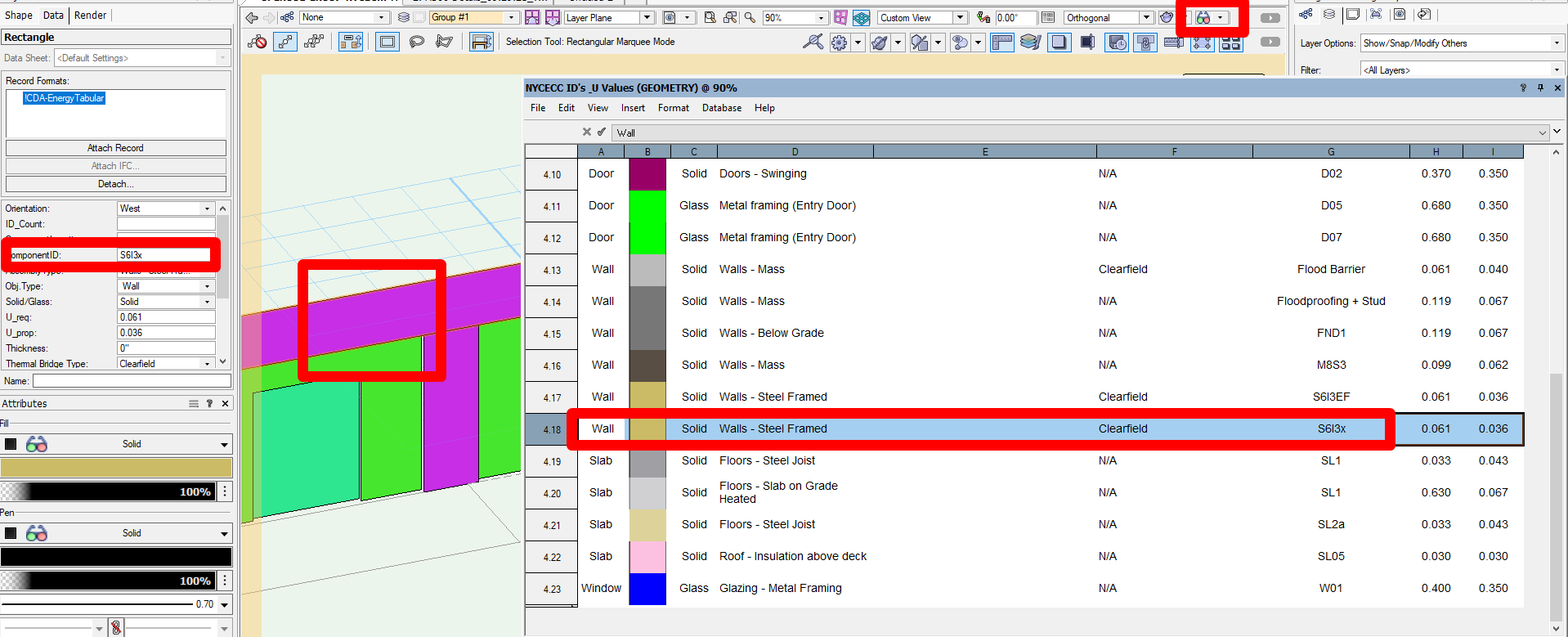
In the case below I have polygons / rectangles that have a record, story, and object type. Essentially they need a unique id / number in order for a plan examiner to cross reference that id with the table below.
1. Create a worksheet script that changes ID count (as shown below) based on a few parameters and changes a field called ID in a record.
(if that is possible). I know it would either be a record callout or a script callout, so i'm not really sure how to do this.
2. Technically the record count can be done without a worksheet now that i am thinking about it because of the unique parameters of each object, story, and count would be able to cover all objects.
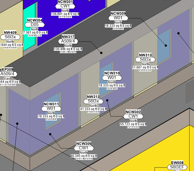
Note : the reason the ID is a separate field is because it used for the purposes of a datatag showing graphically what object that is (2nd image below)
3. The reason for this request is because using the data-tag count system does not work - it counts all tags not only in the sheet layers but also in the view ports. (unless there is a work around I am not aware of?)
-
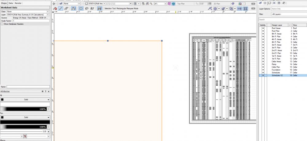
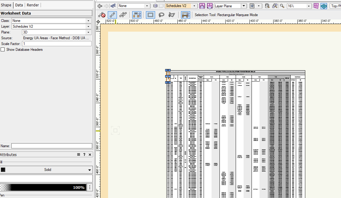
As the post suggests - this bug has a huge implication on construction documents that use worksheets in design layer viewports. Worksheets resize automatically when referenced in a design layer viewport, cropping them makes them disappear.
Beware of transitioning to VW2022!!! This is by far the worst update in the last 4 years that i've experienced unfortunately, and its implications have been disastrously far reaching. A bug has already been submitted, but i am disappointed that it wasn't addressed in the latest service pack. I will try recreating a new file to see if there is something wrong with the file itself because it was originally upgraded from 2021. But this is pretty bad!
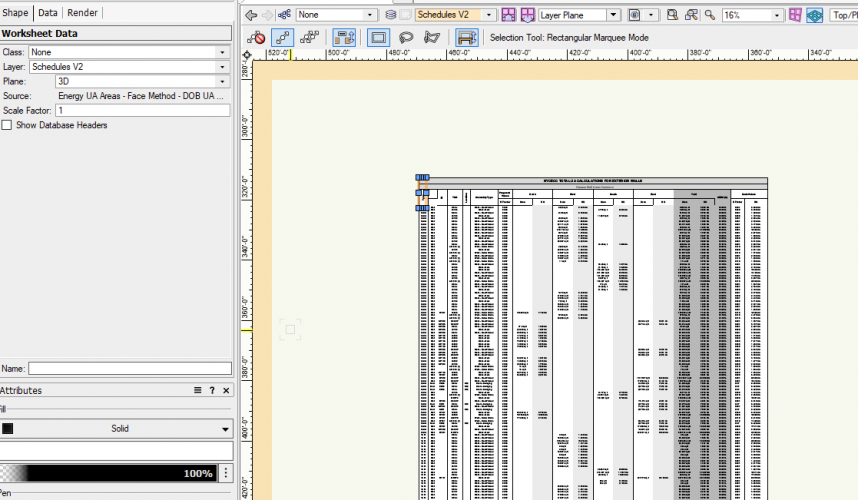
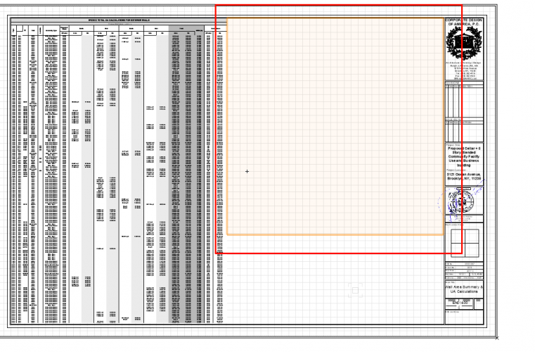
Update 1 - Upon placing in sheet layer viewport - worksheet keeps disapearing. Is this a worksheet issue? or a rendering issue?
-
There are many occasions when a worksheet needs to be resized to fit the viewport, but it cannot when it is fully expanded. Instead of creating a separate design layer and reference worksheets within the viewport, I wanted ask for a new feature - the ability to crop worksheets like images. This would be extremely helpful in resizing and reproducing similar information with copies of the worksheet in cropped formats. Their reference remains the same, but the ability to display selective information would be extremely useful.
-
4
-
-
Hi All,
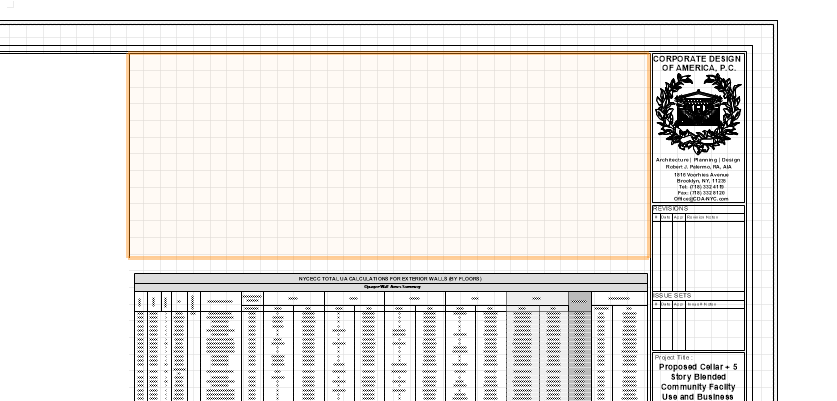
I'm rendering a worksheet referenced in a viewport located on a sheetlayer. When printing pdf, it updates the contents and successfully shows the contents of the viewport when exported, however, in realtime, it does not show the worksheet. Also, VW has a tendency to resize the worksheet as well. It requires a copy and paste - to retain the same size in the design layer viewport.
Viewport Referencing design layer.

Sheet Layer
-
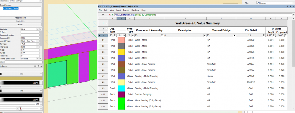
image by datavis ('') - does not properly work, or maybe i'm doing something wrong? Currently display by datavis is enabled, and imagebydatavis callout out referencing datavis name (2nd image). Also, if i change the datavis name to another data visualization - nothing changes.

-
1
-
-
They mentioned on the mac it had disappeared. I'm guessing this is an OpenGl bug - where opengl is still predominant on the windows platform (i presume). It's better than in 2021, so at least that is a good thing. Additionally, 2022 is much speedier in terms of rendering linework than 2021 which is a huge advantage. So i give them the benefit of the doubt, just wanted to give the tech's at the forum the heads up!
-
1
-
-
From what I understand, Opengl was eliminated on MacOs, however, viewport / sheetlayer geometry ghosting beyond viewport still persistent in VW2022
-
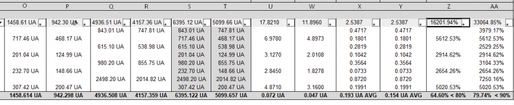
The last two columns are calculating incorrectly
Column Z = P / O
Column AA = T / S
Table cell calculations for
P = =IF((('!CDA-EnergyTabular'.'Solid/Glass')='solid'), '!CDA-EnergyTabular'.'U_prop'*AREA, '')O = =IF((('!CDA-EnergyTabular'.'Solid/Glass')='solid'), '!CDA-EnergyTabular'.'U_req'*AREA, '')
T = ='!CDA-EnergyTabular'.'U_prop'*AREA
S = ='!CDA-EnergyTabular'.'U_req'*AREA
Is there something going on here that I'm not aware of?
-
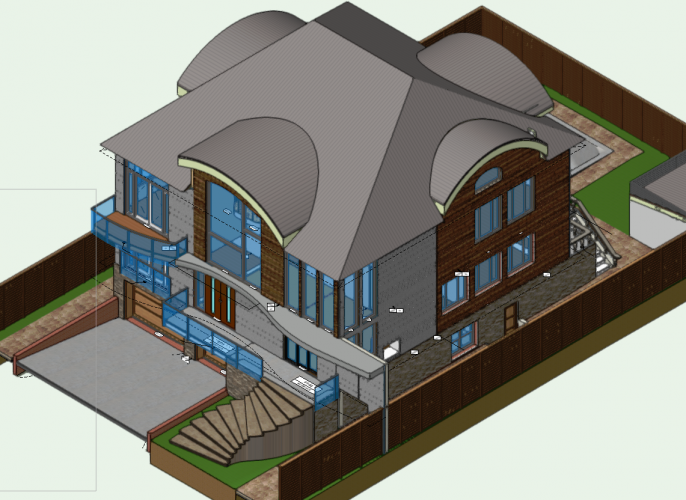
I don't use them that often either, but after making the geometry, i generally get rid of the marrionette from the viewport, and save it as a group symbol in the resource browser should i need it again. If i need to change the barrel roof once more, i would again drag the marionnette into the viewport, verify the barrel roof name and referenced wall type and redo the geometry. I believe there is an option in there that can retain the nurbs surface while regenerating the barrel vault roof.
When i do anything that is out of the ordinary, i also have massing models on another layer in case i need to take the surface geometry from it once more. I also keep design variations on other layers as well, for various options.
In terms of nurbs surfaces there are several ways you can go about it. Either you create a complex shape from two nurbs curbs via the loft surface tool, or (this is generally easier for me to do) create a series of operations on various extrusions. I.E. The original barrel vault roof could be an extrusion, then a series of cuts via the split tool, and lastly, when i get the blocked version result of what i am looking for, I extract the top most surface that I would like to use for the barrel vault. Depending on the settings you use, you can turn the shape directly into a nurbs surface, and then just simply add the surfaces to each other if need be (if they are not combined). Then copy the nurbs surface to the layer you need, name it accordingly and then use the tool for that surface.
Hope it helps!!
Here's an example:
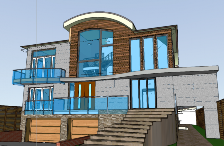
Primitive version
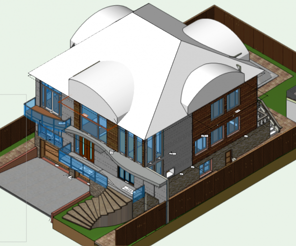
Built out option
-
1
-
-
Try this. You might need to create a custom wall type for the barrel roof you wanted, however, this tool is pretty awesome. It will do exactly what you want, with materials, shape and even creates an autohybrid object.
-
1
-


Data tag - resize text handlebars / text style
in Wishlist - Feature and Content Requests
Posted
Tags in vectorworks are a wonder. In 2021 release (i think ) VW gave us the ability to scale text in a tag - which is wonderful. Another feature that would be great to have is to add constraints to text if the text callout is word wrapped. This is needed because of the way tags are scaled. If the tag is scaled 2x or 3x, the constraints for wordwrap are also limited to the scale. Wordwrap would preferable by unconstrained , or at least an option inside of the tag text options (i.e. constrain some text, others unconstrained...similar to the location contraints in the tag edit configuration)