


Samuel Derenboim
-
Posts
472 -
Joined
-
Last visited
Content Type
Profiles
Forums
Events
Articles
Marionette
Store
Posts posted by Samuel Derenboim
-
-
3 hours ago, Tom W. said:
@Samuel Derenboim see:
Can be used to tag materialmanufacturer, materialreferenceID, etc as well. Unless it's a Compound Material in which case you can only return the Description, Mark + Keynote fields as far as I can tell
Thank you for letting me know! Posted a formula for regular geometry as well.
Will be very useful in the future for detail call outs (creating a custom set). Originally intended on using symbols with custom records for annotation and callouts.
I also noticed a custom record option in materials - it would be interesting to see how that works as well! I will keep experimenting
-
Also, will we ever see text resize toggles for tags? 😁
-
It seems that solution might work for walls. I also use it for regulation geometry
The formula for this would be :
#WS_MATPROPERTYBYNAME(MATERIALNAME, 'materialmark')#
#WS_MATPROPERTYBYNAME(MATERIALNAME, 'materialdescription')#Спасибо! @Nikolay Zhelyazkov
-
 1
1
-
-
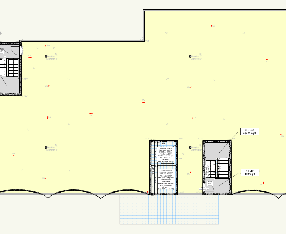
Each detail would be a separate symbol. (to me sheet does not mean sheet layers). If by sheet you mean what is in the design layer viewport - then yes.
Detail number for the detail works, but if it can be detail + drawing name (i.e. . But I will rename each symbol to be the detail name later if we cant do baseflashing for wall deck. etc... (like it is in the detail itself, that would be even better). But if you can't, it's not a big deal.
Yes, I think you summarized my intent correctly.
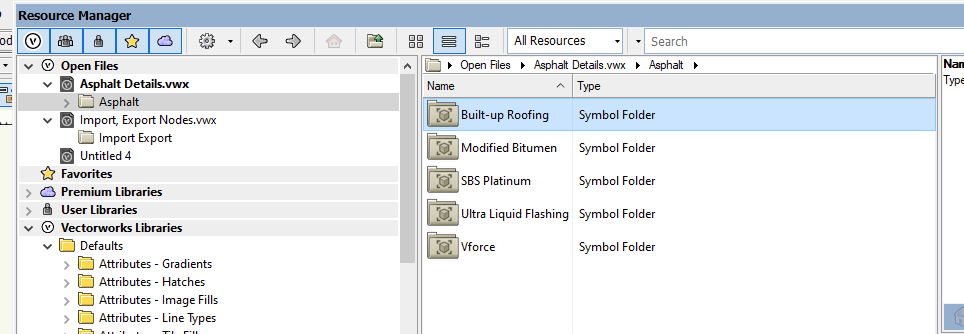
Modified Bitumin would be the parent folder if it only had symbols inside. Modified bitumin is part of an Asphaltic line of details, so it would be best to inherit the folders inside the base folder. I.e. Lets say Asphalt Details => Modified Bitumin => DWG symbols.
Thank you again!!!!!
-
That is exactly the procedure. Thank you so much! Let me know if it uploaded the file fully. If not, I can send a link.
-
😂😅
Pardon my non specificity.
So this is the way i did it previously - import dwg batch - > in advance preferenced i was able to set all lines to black and white. What it doesnt do is import the dwg files into their respective folders.
Then another method came up - using import symbol (batch command)
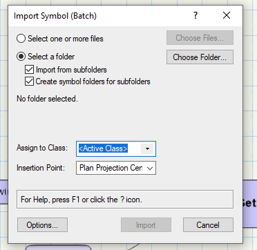
It in turn created all subfolders in the directory!
what it doesn't have the option to do is convert lines to black and white as shown below
But most importantly, it eliminates the name of the detail, and detail no. of the mfg.
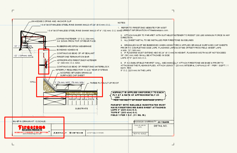
Now if i import the detail as a layer and not as a symbol - it provides all of the information that was in the record (see below)

My concern and original question is
1. How do i preserve the record information upon import as a 'symbol'
2. convert all lines to black and white
3. distribute all symbols in their respective sub-folders when importing from a directory with subfolders
Polylines, rectangles etc.. preferably shouldn't be exploded to retain hatches or fill. i only asked because if the symbol would be converted to group, the information would be retained. But that was a sort of convoluted way of going about it.
-
i figured i did something wrong. lol i think i was able to do it now
-
 1
1
-
-
-
21 minutes ago, Pat Stanford said:
Basically No.
The internal VW scripting model only runs in a single file. This applies to Marionette, Vectorscript, and Python. That means that you can not start a script and have it open a different VW File and manipulate that file.
Long ago I wrote an AppleScript that took a folder of VW files and opened each one and then ran a Vectorscript to export each file to a DWG file.
Something similar could probably be done for your import thing, but since you are on Windows, you don't have the AppleScript option.
If this is a one time conversion project I might be able to help. If this is an ongoing need, then I don't have any other great ideas.
Thank you for your response regarding this matter! unfortunately yes this is ongoing. Ok, ill drop that idea, however i noticed that with import symbol (batch) - vectorworks can import dwg files by folder quite seamlessly, however there are still a few things i want it to do while it is importing which is -
batch import = > explode all symbols = > convert all lines to black = > proceed with import
-
I'm Having a bit of an issue with importing dwg files as symbols as it does not do a few things i prefer like :
1. import folder structure the dwg subfolder directory
2. import / convert to group any elements that have record information (normally does not import record information as nested symbol)
3. name all symbols by record name (inside of symbol) rather than file name of dwg file.
I thought about going about it a little differently -
batch convert to vwx in place, and then reimport every vwx file as a symbol.
Another workaround can be convert bulk dwg files in place - but with every action save extents of imported layer as symbol
I feel like this can be done with the marionette tool - however i do not see any nodes for :
1. creating symbols
2. opening vwx files
3. converting design layer to symbol
Is this possible?
-
ah, thank you Tom!
-
Will we ever be able to pull material data information into a data tag?
I noticed in order to pull it in a worksheet - command is something like :
=MATPROPERTYBYNAME(B3, 'MaterialDescription')
=MATPROPERTYBYNAME(B3, 'MaterialReferenceID')
=MATPROPERTYBYNAME(B3, 'MaterialManufacturer')
etc...
Will we be ever able to do the same thing with data tags?
-
Beautiful!
Is this for wireframe? or shaded background renders only?
-
4 hours ago, Pat Stanford said:
I agree with Christiaan. The people at VW are trying to do the best job they can with the resources they have. I am certain that the sales/marketing/management at VW are aware of all the options and impacts that this change will have. They have watched the industry move in the subscription direction for years. They are not suddenly going to a new model that no-one has ever tried before. And based on their research and experience they are doing what they think will best benefit VW.
If it benefits VW then it must also benefit (or at least not harm) the majority of users. Will it be the right thing for all existing users. Absolutely not. Will it be the right fit for many on this thread? Based not he responses, probably not. But the users of this forum are a tiny fraction of the total number of users.
And please give the VW people some credit. I am sure this was worked on for a very long time. None of us like it when someone with no understanding of the requirements or site conditions criticizes our designs that were done to the best of our ability. VW personnel feel the same about this.
My $0.02. Written for my personally, not in my role as a moderator or in any way representing VW.
I agree, the people that develop the software I am sure that they are in 100%.
Your help alone in these forums helps a tremendous amount. The fact that the programers/developers in VW also participate in the conversation is a huge deal.
Having said that, how will the subscription system help ?
Is it intended to increase the development team? or provide better updates? Will your salaries increase due to this condition?
If so, couldn't that simply be solved by increasing the price for entry for permanent licenses - and why will that option no longer work?
At the end of the day, is it the development team that determines whether or not features get released? or whether it is the appropriate time to release them? or is it management? I just am under the guise that management is divorced from development despite how well intentioned and passionate the team is...unless I am mistaken, then Ill certainly eat my words.
-
1
-
-
9 hours ago, shorter said:
there was another that reversed that result…Can you share a source?
Also regarding my assessment wasn't regarding a hunch, but rather demand. Go to Archinect or any other website that provides job listings.
On Archinect, search for vectorworks as a keyword. Only 26 jobs available throughout all of United states ( not sure if it covers UK).
Do they same for Autocad. 673 results. Revit renders 764 results. Archicad renders 45.
Total search results: 1508
Autocad - 44.4 %
Revit - 50.6%
Archicad - 3 %
Vectorworks - 1.7 %
These are real-time numbers that currently list jobs available today.
As a reseller of VW, I understand your position, but at least be fair.
-
3
-
-
- Popular Post
- Popular Post
My hunch is that this move will get people away from Vectorworks. Vectorworks, despite it being a very powerful software, doesn't have a large enough base in order to sustain interest in the event of a subscription model due to its sparse use among the industry. Instead, practitioners promote its use because of the one of the core benefits Vectorworks provides for them - a perpetual license (additionally to the software features of course).
What I find Ironic is that after looking at Archicads forums, it seems that despite being under the same corporate entity, they will still be providing perpetual license options post 2023.
My question is - why not offer it as an option ? rather than forcing everyone into it? Why does it have to be one or the other?
-
9
-
As described. Working with roof drains is becoming a nightmare with the new edition of vectorworks. This is by far the buggiest, most unstable version vectorworks that has been released to date. 🤬
-
1
-
-
Latest update broke roof line slopes when having graphics acceleration turned OFF. Techs have advised for previous updates, worksheets referenced via viewports disappeared with graphics acceleration turned ON. Either way , problem persists, and it is quite frustrating. Can anyone confirm they have similar problems?
-
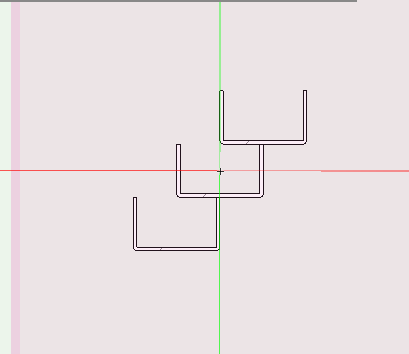
As shown above - revision cloud tool doesnt work from the native toolbar nor from the convert to object menu.
-
I added another door size to Marvin patio door catalog and tried to modify Frame finish record. This consistently crashes vectorworks. This has been repeated multiple times, latest version of VW service pack 2.
Are entries un-modifiable for catalog items?
-
Hi everyone, I don't seem to be able to find a node that can create symbols. I did manage to find one that was written by domc, but it only creates a symbol in 3d space. Code is below.
Is there any way i can modify the configuration so that the objects being inserted go to 2d space, not 3d? I am trying to create a marionette program that creates symbols from groups - that have certain records. There has been other ones that have been done with creating symbol by object name (including groups) but it only works on single objects, groups do not show up in the 2d annotation space, thus disappearing
#DomC v001
@Marionette.NodeDefinition
class Params(metaclass = Marionette.OrderedClass):
By = 'DomC';import datetime; now = datetime.datetime.now(); y80f5 = now.year;m80f5 = now.month; d80f5 = now.day; h180f5 = now.hour; mi180f5 = now.minute; s180f5 = now.second; ms180f5 = now.microsecond; h280f5 = h180f5-12 if h180f5 >=13 else h180f5; VersionChange1 = str(y80f5)+' '+str(m80f5)+' '+str(d80f5); VersionChange2 = str(y80f5)+'-'+str(m80f5)+'-'+str(d80f5)+'-'+str(h280f5)+'-'+str(mi180f5);
TextStatic = Marionette.OIPControl( By +' v'+VersionChange2, Marionette.WidgetType.TextStatic, "")
this = Marionette.Node( "Create Symbol" )
this.SetDescription( 'Creates a new Symbol' )
h_obj = Marionette.PortIn(vs.Handle(0))
h_obj.SetDescription( "symbol content (one object) if empty, an empty 3D (3D Locus) symbol will be created" )
s_name = Marionette.PortIn('Symbol-1')
s_name.SetDescription( "the symbol name" )
s_sym = Marionette.PortOut()
s_sym.SetDescription( "the result symbol name" )
h_sym = Marionette.PortOut()
h_sym.SetDescription( "handle to the newly created symbol" )
def RunNode(self):
obj = self.Params.h_obj.value
name = self.Params.s_name.value
vs.BeginSym(name)
vs.Locus3D(0,0,0)
h = vs.LNewObj()
vs.EndSym()
vs.Marionette_DisposeObj(h)
h_sym = vs.GetObject(name)
vs.SetParent(obj, h_sym)
vs.ResetObject(obj)
vs.ResetObject(h_sym)
self.Params.s_sym.value = name
self.Params.h_sym.value = h_symI think the problem lies with the create symbol node. See screenshots below. Seem like i just need a create symbol node with more properties, or just a 2d symbol node.
1. Design layer space
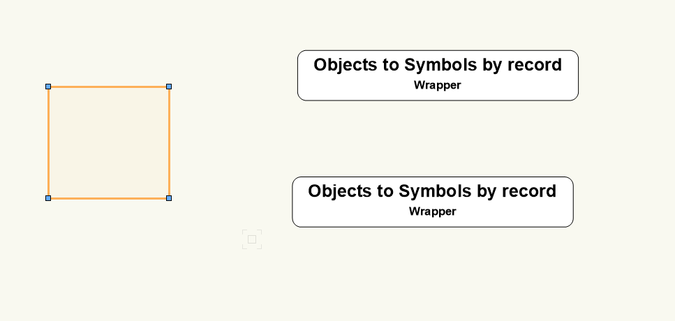
3d view space
-
arquitextonica,
there unfortunately (at least to my knowledge) isn't any whitepaper that would probably help you. Having said that, I've dealt with several very large buildings and was able to make it work. Here are a few recommendations i have done. I can also tell you what i plan to do better in the future
1. Referencing files into one master file is very important. One problem you will come across are stories - and your workflow needs to be be similar in every file.
2. Tagging wall objects/ floor objects/ window objects need to be done in the original reference file - not the master file. This is very important.
3. When working with worksheets, notes, etc... consider each portion of the set of buildings - as a separate building. Worksheets will not be able to be combined, nor will takeoffs. I still need to verify for myself whether or not worksheets can make take-offs for multiple reference files - not just the file it is in. Try this for yourself
4. Experimentation is key. If you have an idea, test it out on a test file to see if it works. You can start with the idea above. Create two different files with two different wall types, roof types etc... Then reference the two in a third "master" file and create a worksheet. Do both wall types show up in the schedule?
5. The master file should be able to have sheet layers. Be careful not to overdo it with the amount of sheet layers in the master file. If you can, split it into various sections. I for one split it into a. plans / rcps (000, 100 series), sections / elevations (200, 300 series), detail sections (400 series) and details overall (500 series) --- each with their own set of worksheets. Think about how you will create the set for each building on the block before you integrate it. This is very important if multiple people will work on the project as a whole.
6. Try to have a file that has all the wall types to be used between all the files separately - that way multiple users can access it. This will be useful when making takeoffs, needing to change wall types, floor types in different files with appropriate descriptions, UL #'s, R / U values, etc...
7. Create a master pdf set of documents in a separate directory for each sheet separately. This is important because rendering elevations and sections take a while. Doing each separately and combining them all (already pdf's) when needed will create a much quicker workflow.
8. If you have additional filing's to do like builder's pavement plans, site plans, do those in separate files as well - as a whole. They are much simpler, but with more complex mechanics when figuring out cut / fill, sidewalk elevations and slope percentages, curb cut depths, and grade / flood plane elevations.
there some features that might not work in referenced files like :
1. if a file is reference with a column grid - I do not know if the column grid will show up in the section if the master file is referenced.
2. schedules / takeoffs in referenced files - still unknown.
3. do not tag wall types in reference files. It doesn't work. Its a major flaw in VW
I'll add some more if i remember anything else. Hope this helps.
As for your question above, classes and design layers are easily manageable in reference files. Just be consistent in the way you assign classes to wall styles, floor styles, window styles etc...If it is consistent, using the eye tool, you can eliminate or turn on elements in a drawing if you have to.
-
1
-
-
That was why i used the analogy of the material type. Since it is already a "plugin" object - it should remember the custom class configurations as you saved it without having to add an additional record to the window or door. COBie is just one additional custom element. There are quite a few more - include UL designs, noise isolation class, impact rating, and / or other ANSI design categories fenestration need to comply with. Masterspec can be another for classification, perhaps closers or custom hardware for doors / windows. The list keeps going 🙂
-
What would I think could be even more beneficial is if we can assign custom field information similar to the way material information can be called out. Those fields can be used a multitude number of ways not just limiting to cost code index. Below is an example screenshot for custom fields in a material. Would be great to have similar conditions for walls, windows, doors and floors. What do you think?
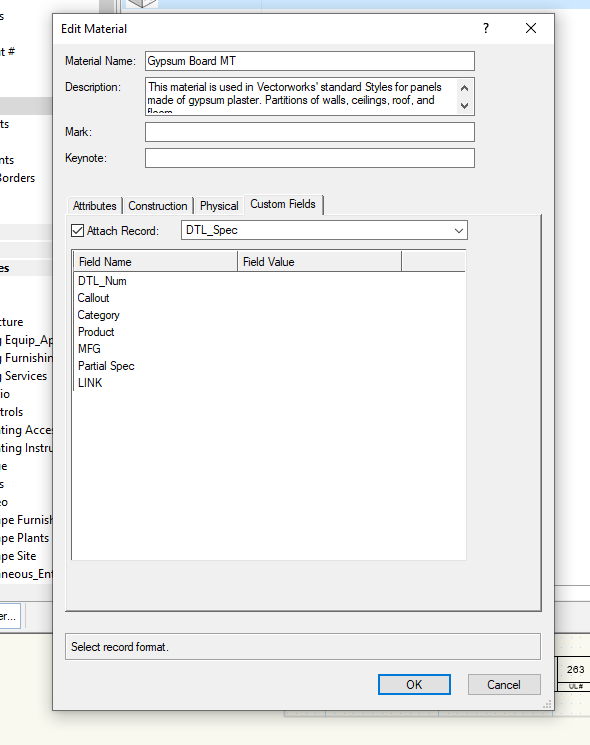
Request for a “ComponentMaterialProperty(propertyName)" worksheet function
in Wishlist - Feature and Content Requests
Posted · Edited by Samuel Derenboim
@Nikolay Zhelyazkov
In that case, Благодаря ! 🙂
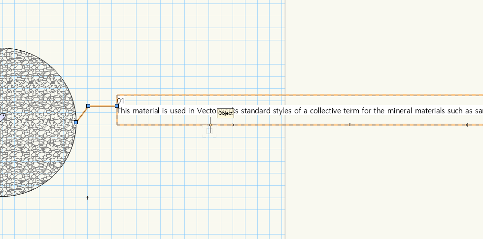
Also regarding your question - see screenshot below. This is a comparison between a tag vs a annotation callout . A callout has toggles, but no database reference.
It would be nice to resize text like a callout in a limited size viewport in case it is needed.
(also, I have a hunch that a future feature - legends will work very similarly to a tag, only summarizing in bulk all of the elements referenced...might eliminate this need entirely if the text in the legends can be resized similarly...
I also have a hunch that you are also directly related to that feature!....but alas, it is only a hunch! 😁 )