
Samuel Derenboim
-
Posts
472 -
Joined
-
Last visited
Content Type
Profiles
Forums
Events
Articles
Marionette
Store
Posts posted by Samuel Derenboim
-
-
4 hours ago, JMR said:
And, if you set up a housekeeping window schedule that lists all windows regardless of the "include in schedule" setting, you won't accidentally miss any windows. I guess you could also pull up the window configuration data to the housekeeping worksheet and thus immediately see which is just an opening.
I agree, that's a good idea
-
One thing it to note - there is a limitation in the number of point you can see inside the model, so breaking it up into pieces is important. And also, make sure the scales match based on the laz file. sometimes the output from faro or leica cyclone (what i used) can be in a different measurement. The reason i know is that i ran into that problem.
-
Don't know if this is possible, I didn't see an option for this in the general options, but is it possible to callout the gross wall area of a Wall and Cwall?
On worksheets the tag is =WALLAREA_GROSS, but i can't seem to be able to use it or access it in the data tag dialogue.
Preferably i would like to call out Wall, window, door and floor areas out in data tags (Building department requirements). Don't know if the same functions will work for the as well.
Any ideas?Thanks in advance!
-
 1
1
-
-
Hi Again,
I wasn't able to fix the problem, but i know what it is. Apparently if a loop inside a worksheet crashes VW, it saves that condition upon re-opening the file, and ultimately corrupts the file.
So Dev's need to implement worksheet window to close upon opening VW to fix the issue, otherwise the file corrupts
-
Hi All,
Vectorworks 2019 permanently corrupted 2 files I've been working on in the past 5 hours. By the looks of it, there must have been conflicted information in worksheets and custom records being used by datatags. This happened when I modified a custom record from a worksheet linked to a datatag. In another case, i modified the record directly, and the program crashed. Don't know what the cause is, but afterwords, vectorworks wouldn't want to open the files again. This is very stressful, especially since I have a deadline. I will lose 5 Hours of work unfortunately due to this problem. 😖
I've updated to SP v 1.2 prior to corruption. There was a consistent amount of crashing due to worksheet malfunctions. This is the first time I've had VW permanently corrupt 2 files. I can't seem to be able to upload it either, perhaps because I'm currently writing from abroad. Please let me know if there is a way for them to be recovered.
Also, this is what the .lck file generated
<?xml version="1.0" encoding="UTF-8" standalone="no" ?>
<FileLock><FileLockInformation>
<User>Samuel</User>
<Computer>DESKTOP-D9T06VJ</Computer>
<LockedTime>3624248431</LockedTime>
</FileLockInformation></FileLock>
Thank you in advance!
-
+1 here as well!
-
Hi all,
This is strange, i didn't change anything, but all of a sudden it started working....but in a different file from the original....
Is there a refresh problem?
-
Hi all again,
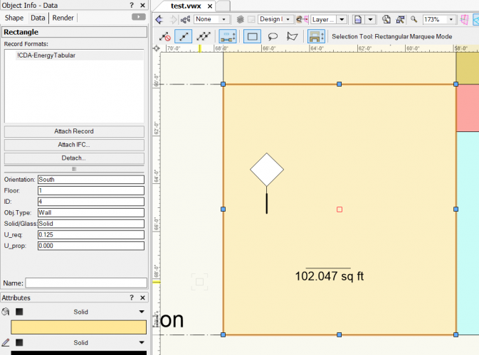
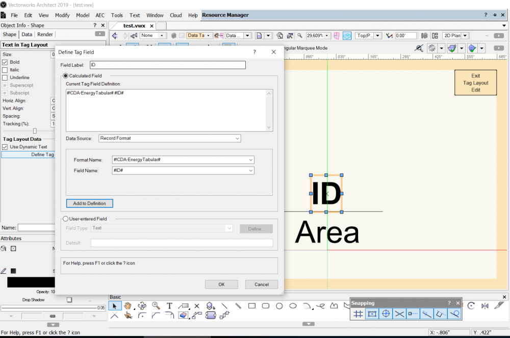
I'm trying to use a data tag with a custom record. A general length call out for the rectangle works, however a custom record doesn't show up when called out in a custom tag.
As you can see below, data tag calls out for the custom record, but it doesn't show up when used.
Maybe i'm doing something wrong?
-
just uncheck the include in schedule option -when you go into the door properties options.
-
Hi Jeff,
I was thinking about that too. Considering now that the new id tool can display a local callout, while at the same time the item can have a detailed specification on a separate record of the same object. Or, you can add them in a worksheet when calling out all items you wanted to specify out of all your records.
But, i feel that option might be a bit too tedious.
-
Hi everyone,
Another questions regarding worksheet functions. Is it possible to call out which windows/doors are located inside a particular wall type?
We generally need this information for energy requirements, and was wondering if something like that was available parametrically. I'm trying to call out wall style name, window ID, and door id and i get the following:
is there a way to integrate wall style id and the objects located inside them using conditional statements in a worksheet?
Also, is there a way to just simply call out a wall type id? I can no longer see that option in the 'records' drop down menu.
Either way, thank you in advance!
-
I tried doing that, but then the text gets unbearably large, and all the window menu items are also overbloated in size. Here are the things i've tried so far:
properties settings - high dpi scaling override - system (enhanced)
Lines are extremely blurry and interface is almost unusable. However, plugin settings work at full screen. The curser however is extremely small.
Then with 200 % scaling (default settings, no system dpi alteration)
The plugin settings at 200% barely fit, but at least theyre modifiable. However, user interface for windows (icons, etc..) are too small for the 15" screen
With smaller resolution and default settings :
Application is relatively stable, however top view is still blurry. Otherwise plugin settings work. The top plan view settings work best at native resolution, but plugin settings work best at 175% scaling or reduced resolution. Can't win here. 😕
Will have to use option 3 as it is the best of all worlds.
Thank you Jim for your help...If its possible though, perhaps this problem could be fixed in the future? meaning - allow scaling up to 225% (4k resolution on smaller screens)
-
Thank you Jim,
I can see the difference, but then the desktop user interface becomes way too unmanageable for proper use on a small 15" screen. Any other work arounds?
I tried lowering the resolution, but then icons start to get blurry too....
-
-
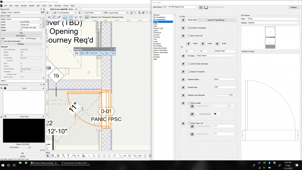
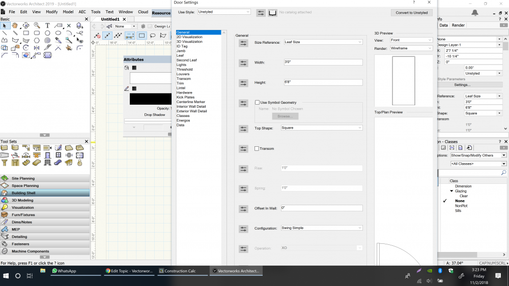
Ok, i'm starting to realize this might be a major bug. After downloading a resizing / windows moving application - for some reason the preview window elongates the top/plan preview no matter what i do. I tried resizing it with no avail.
Any have similar problems on smaller screens?
-
Hi Everyone,
First time i ran into an issue because I started working from a laptop. I used a workspace that allowed for a higher resolution and all the window screens for doors, windows, data tags, etc... fit inside. Now that i have a lower screen size and import the same workspace, the windows dialogs extend beyond the screen. Any way of getting them to fit without changing the workspace?
Note: window key + left / right works, but it doesn't resize the window vertically
Thank you in advance!!
-
Thank you! Looking forward
-
Hi everyone,
Noticed that the data tag is missing a few key features (unless i'm missing something). Is there a way to get Z value, or Z value above grade in a data tag tool? It would be wonderful to just call out the z value of a slab on the 2nd story to show what its elevation is above grade / datum. Is this possible?
Thanks in advance!
-
same here, does windows 10 report crashes like win 7 did?
-
That plan as you can see isn't very simple either. Custom selection helps dramatically. In either case, I can't always wait for VW to help, but you can send the file to tech support, see what they can do, at least that's what i did earlier today.
It took me all of 20 minutes experiment for the solution and another 10 to carefully modify the file.
But trust me, I have a deadline this Friday myself, so I've been doubling down on solving this problem myself.
Good luck in getting yours straightened as well!.
-
 1
1
-
-
Leecalisti, I figured out how to fix it.
Before modifying the file, make sure you make a backup. However, this is the way i fixed it.
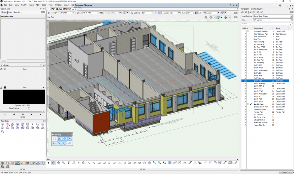
I created a new layer - to be on the floor plan as the original layer. then I slowly started cutting and pasting the objects from one layer to the other. Make sure you have OpenGL set on 3d viewing. every time you cut and paste a new object, check to see if it now appears (one by one) in the new layer. For me, after i custom selected all the walls, i went into 3d to check if they appear at that time. Make sure you do this upon every cut and paste object. I feel sometimes there might be a 'problem' object that's preventing the screen from refreshing.
Then slowly custom select the rest of the objects - 1 by 1 (in terms of object type).
I did this the first time, and it didn't work because i didn't switch to 3d view open gl mode, and as a result it replicate d the same problem as before.
Once i did it this way, I was able to restore the layer that had the problem. Usually - this occurs with one or two main layers that you might have. Once you restore the layer, delete the original, and set the story level to the default story level, whether it be finish floor, slab, etc...
Make sure you save between every copy, otherwise if you copy and paste - to make sure you don't copy the problem object that corrupts the layer.
Let me know if this works for you.
-
Note this is a several day old back up file....it isn't the current one. What is it that could have corrupted the new file? I just need to know to avoid making the same mistake....
Also - Is corruption permanent?
-
-
Just checked the 1 monitor option - unfortunately i still get the same result....


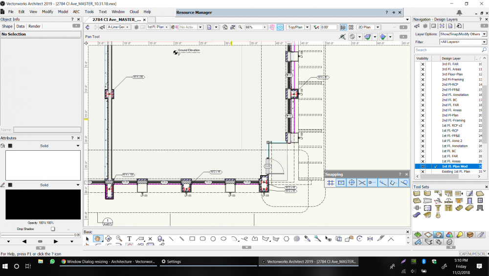
ceiling tool bug
in Architecture
Posted · Edited by Samuel Derenboim
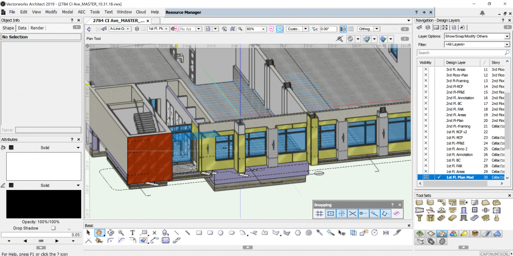
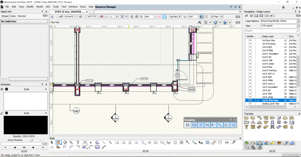
For some reason when i modify a ceiling grid element, i have to move the points twice, or rather the movement doesn't fully refresh for some reason.
Can someone confirm please? If need be i can upload a sample.
Just rechecked the problem - the problem only persists if it has a lot of edges. regular rectangular ceilings work right the first time. perhaps a memory problem?