Elite Exhibits
-
Posts
583 -
Joined
-
Last visited
Content Type
Profiles
Forums
Events
Articles
Marionette
Store
Everything posted by Elite Exhibits
-
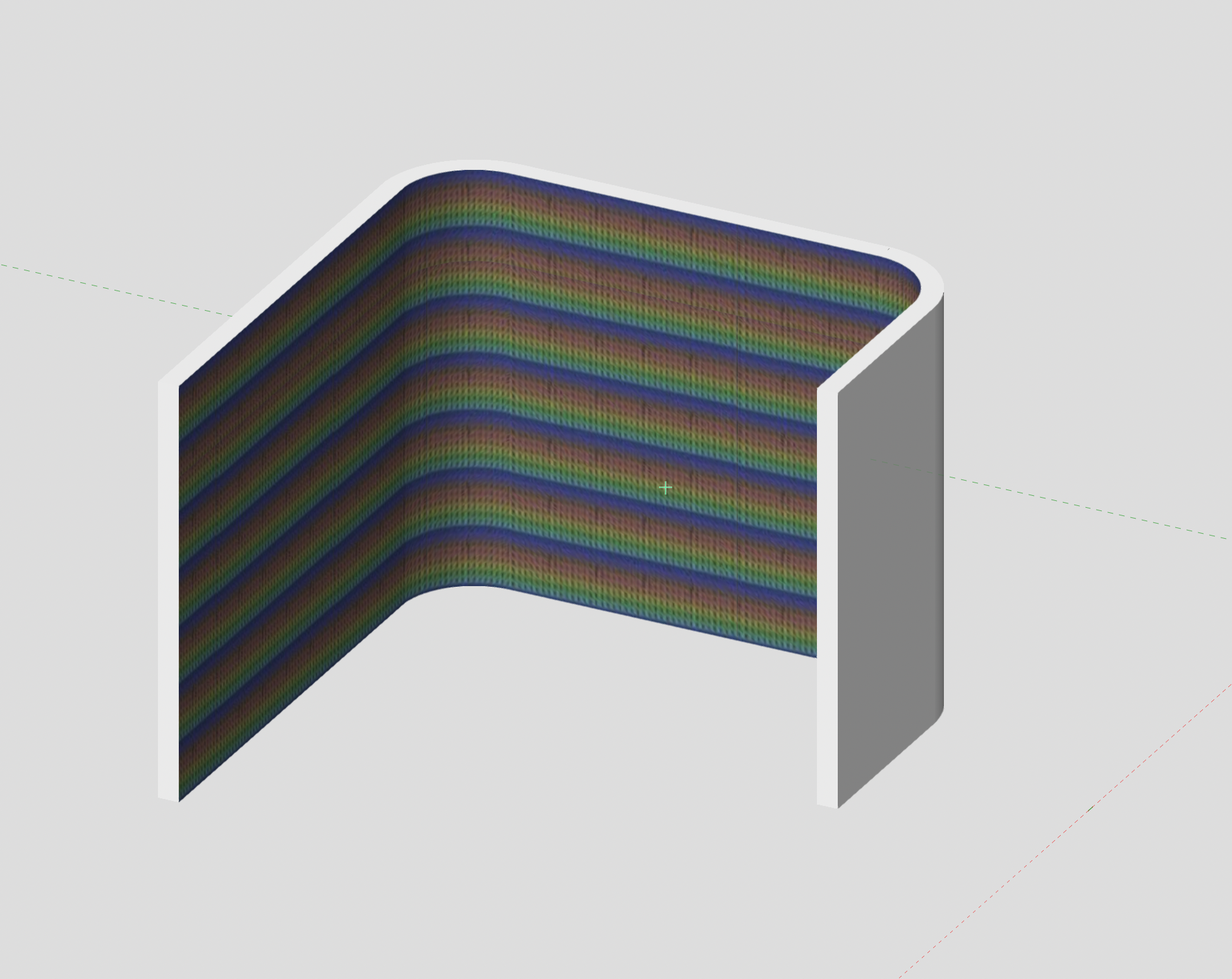
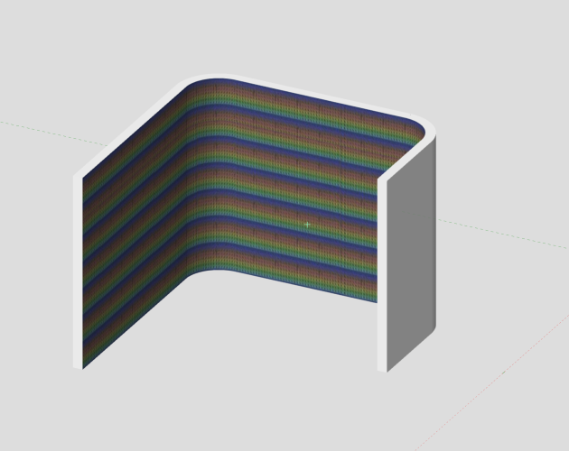
@grant_PD as for alignment, Note how the Texture is created & applied in RGB Walls_1 Let me know what you see... Peter
-
@grant_PD open the RGB Walls_1 file above ... as @Mark Aceto mentions - use walls - created from Peter
-
@grant_PD @Kevin K I have created something along this line - started with a polygon - created a wall from that - then mapped the texture to one side of the wall. See attached Peter RGB Wall_1.vwx

-
@Jeremy Best Thanks again for the info Like many other Vectorworks issues, I have given up on this ever being corrected. The only app with Open / Save dialog box size issues (...on my MacBook Pro M1) is VectorWorks - So ... ¿ What to do ? Checked again on this issue No external monitors Nothing externally connected to the laptop No "Default Folder" app Quit VW 2023 Delete ".plist" for VW 2023 Empty Trash Restarted Computer Started VW 2023 SP6 ...still have Open / Save dialog box size issues. See attached Peter Open_Save Dialog Boxe size Issue_1.pdf
-
When is 2D, 3D but not really, actually, completely 3D ? Unfortunately, this is NOT obvious in the process, (if Darin K's geometry is ...) a Layer Plane Rectangle, it looks 3D, edits Z as 3D and generally acts 3D... One should consider it to be 2D as VectorWorks does not like to Texture a Layer Plane Rectangle. As @Tom W. mentions above, Image map is the trick. or as @jeff prince states make it a real 3D item. We coach people to stay away from Layer Plane geometry to skip such aggravations as the @Darin K problem encountered above. A rectangle, extruded to Zero will behave, not unlike a Layer Plane Rectangle, except it will texture as a 3D item should. What also creates frustration / aggravation is the How in applying the desired look Darin K is after. Attributes Pallet for the Image on Layer Plane geometry OIP / Render Tab for a Texture on 3D geometry. Top this off with the fact that one is able to drag and drop a texture, from the Resource Manager, onto Layer Plane geometry and also apply an Image onto a 3D component in the Attributes Pallet. To the uninitiated, both worked except ... they only look like they worked. See the attached Peter Image Map on a Layer Plane and an Extrude.pdf
-
Callout Text Centered after Edit - ¿ How to Keep it Centered ?
Elite Exhibits posted a question in Troubleshooting
Callout Text Centered after Edit - ¿ How to Keep it Centered ? Question: ¿ How to keep the Callout Text Centered after editing ? Not the Horizontal Text Alignment option in the OIP - in reality. If a Callout is on the drawing (No Leader Line) with the Center option selected, when this Callout is edited, it does NOT stay centered. The Max Text Width appears to be a determining factor. Assume that there should be an Automatic option in this OIP selection. Question: Is there a way to write a Script to set the Width of the Callout Text to match the actual Text in the Edit Callout Dialog Box (... as it is with regular text) ? Suggestions ? Peter -
Edit Contextual Menus ... Locate in Resource Manager option Question: ¿ How do you edit the Edit Contextual Menus so that Locate in Resource Manager option is at the top ? While this Locate in Resource Manager option appears when drawing, it is NOT available in the Left side list (All Menus), nor is it shown in the right side list (Context) when editing the active Workspace (Workspace Editor) (¿ WHY ?) Hard way around the block might be ... Script - Menu Item - Add to Context menu at the top. Current project is dozens of Hybrid (Screen Plane / 3D) Symbols to edit Would make like much easier See attached Locate Symbol_1.pdf
-
@Pat Stanford Reference Got the script you created for Bruce (... in the link above) to work for a current project. The question is - Why do simple (Insert Worksheet Function) Width & Height return valid numbers in a worksheet (...without that script) and Length does not ? Width and Height appear to be the 2D X & Y dimensions ... (Length & Width in this case) Is there a simple way to get the Delta Z of the Symbol ? One might assume that =TOPBOUND-BOTBOUND would be it. (¿ Obsolete ?) See attached ¿ Possibly, there is NOT a way to do this as the Extrude is inside a Symbol ? Peter Crate Worksheet_Forum_2.vwx
-
Question re: Symbol with Callout - How to get the data into a Worksheet ? Put this under Data Tags as that may be a better solution ... (?) Symbols represents shipping Skid / Crate / Case All are 2D/3D Hybrid In the Top Plan Foot Print is a basic rectangle = overall size Name & Size are shown as a Callout In Perspective Extruded shape is a simplified cubic representation. Used Callouts for the name / dimensions inside the Symbol as it is easy to show a Callout in a Worksheet (vs plain text). Question: How to show the associated Symbol name if the Worksheet / Database is counting the Callouts ? or How to show the associated Callout name if the Worksheet / Database is counting the Symbols ? Please see attached (Able to edit these Symbols for simplicity if needed) Any appropriate advice and applicable answers, as always, are aptly appreciated. Peter Crate Worksheet.vwx
-
Unified View Turn it Off or maybe Turn it On ... Even if you only have a single Design Layer Peter Unified View Missing Items inside Container_237.mov
-
@Benson Shaw ¿ What FONT are you utilizing ? Peter
-
My 2¢ For the Mac Converts Vector based PDF to DWG - then DWG import into VW Peter PDF to DWG.pdf
-
Re asking the Question: Why Align/Distribute does NOT work... (VW 2023 SP6) Posted this question here as the original title came up in a Google/Forum Search Maybe the question should be: Why Align/Distribute does NOT work as expected See attached file - Extrude and Layer Plane (3D) Polylines do not align in Top/Plan view as expected. With 2D Align nor 3D Align - ¿ Is a Layer plane Polyline 2DS or 3D ? ... the OIP lists it as 3D ? Able to Move by points and get the expected results. Wanted the Align command to do the work with out the need to touch the objects. Intent is to put the Layer plane Polyline on the face of the extrude. Original components imported into VectorWorks. Noted above - Align does NOT work on PDFs - Does the VectorWorks HELP indicate this ? - assumption is that the VectorWorks HELP does NOT indicate other conditions where the command does NOT work as expected. Any appropriate advice and applicable answers, as always, are aptly appreciated. Peter (VW2023 SP6 Mac 12.6) Align does not work Top_Plan v2018.vwx Align does not work Top_Plan v2023.vwx
-
@Jack2022 Here is some information for your perusal My 2¢ There are some issues - VW 2023 / SP6 appears to fix some things (see below)The coffeebreak is good, except what we have experienced as "problematic" is not directly covered in the discussion as some items are existing / pre-prepared. Peter Graphic Legend GRAPHIC LEGENDS . ANNOTATIONS HUGE PROBLEM!!! Graphic Legend Cell looks different in the edit mode compared to the sheet layer version ... https://forum.vectorworks.net/index.php?/topic/108998-graphic-legend-cell-looks-different-in-the-edit-mode-compared-to-the-sheet-layer-version/ Graphic Legend https://forum.vectorworks.net/index.php?/topic/101534-graphic-legend/ Graphic Legend summarize symbols https://forum.vectorworks.net/index.php?/topic/109139-graphic-legend-summarise-symbols/ Graphic Legend R-Values https://forum.vectorworks.net/index.php?/topic/108542-graphic-legend-r-values/ Graphic Legends https://forum.vectorworks.net/index.php?/topic/104060-graphic-legends/ Graphic Legend Coffee Break https://university.vectorworks.net/mod/overview/view.php?id=5180 Graphic Legend 2023 HELP https://app-help.vectorworks.net/2023/eng/VW2023_Guide/Annotation2/Graphic_legends.htm?rhsearch=graphic less&rhhlterm=graphic
-
MINICAD / EARLY VW FILE CONVERSION and UPDATING CONSULTING GIG
Elite Exhibits replied to bbrown6's topic in Job Board
When requesting a conversion to update them, I have been told by VW that the MInicad file I needed converted were to old ... Ugh ! Peter -
¿ Is a New How to submit a bug report needed ?
Elite Exhibits replied to Elite Exhibits's question in Troubleshooting
Pat Interesting What I see is ... bugsubmit@nemetschek.net Will retry with bugsubmit@vectorworks.net Thanks Peter -
Question: Searching for How to submit a bug report brings up the following with information that is no longer valid ? Is there a different How to submit a Bug Report ? Peter
-
@Tim C. This thread is similar to others on the FORUM - appears that there are continuing constraint adjustments issues - VectorWorks 2023 SP5 Have filed a bug report indicating this. Others have voiced their concerns Peter
-
GRAPHIC LEGENDS - ANNOTATIONS HUGE PROBLEM!!!
Elite Exhibits replied to Shortnort's topic in Architecture
We have experienced a possible source of conflict in the Graphic Legend Layout Constraints In our case, adding text and a second image caused an issue until we unchecked the Graphic Legend Layout Constraints for other than Image-1. As these Graphic Legend Layout Constraints are auto applied by VectorWorks, it is assumed that they do NOT conflict with each other. My 2¢ Peter -
Again... I think I have my own answers. In the Edit Cell Layout mode, the Graphic Legend Layout Constraints, for Image-1 are able to remain "the default" as VectorWorks sets them. However, "the default" Graphic Legend Layout Constraints for Image-2, however, will equate to a Graphic Legend that does NOT look like what is shown in the Graphic Legend Cell Layout . ¿ Why might be the question ? Or is it just another inexplicable aggravating anomaly in VectorWorks see attached My 2¢ Peter Graphic Legend Layout vs Cell Layout.mp4
-
Graphic Legend only shows 1 cell.
Elite Exhibits replied to hollister design Studio's topic in General Discussion
Pat I think I have my own answer ... It is quite convoluted how the Define Legend Source Works in this case. (If you are able to Speak French, it is easy to go to Paris. But until you learn to speak French...) Confusion: Knowing that there are a set number of Symbols that The Graphic Legend should reference / represent (10 in this case) Seeing different Number of Cells in the Define Legend Source dialog box dependent on the Report By selection. One number, 5, you assume represents only a single instance of each Symbol in the file (Resource Manager) the other being, 10, the total Symbol count on the only design layer. When selecting Symbol as the Legend Source from the Define Legend Source dialog box. Note: there is no additional delineation in this example. As you want the Graphic Legend to show ALL 10 Symbols on the drawing, reverse logic, and the Report By selection should be the one that appears to represent only the 5 Symbol ie:a single instance of each Symbol. Further Confusion in the Sum Values check box in the Define Dynamic Text dialog box, under Value Display. It does NOT need to be selected to have the Graphic Legend Cell sum total instances of the specific Symbol with the Cell Layout Data (Text) Function defined as Count-#CT#. ¿ This appears to be the reverse of what would be needed in a Worksheet ? ... the Sum Values check box only alters the text in the Cell, not the combining of matching Cells (Symbols)? Additionally, while the Summation of Cells appears to be automatic, it did not occur, (as in your reply above...) even with Graphic Legend Recalculate button in the OIP, until VW 2023 SP5 was shut down and restarted. (Possibly another Inexplicable aggravating anomaly) My take ... Peter Peter -
Frustrating struggle to understand why I am able to edit a single example cell (even check how other cells will look) yet the Graphic Legend looks different in the full sheet layer version compared to what one sees in the edit mode. ¿ Missing some check box ? Noticed that some indicators disappear when Detail is checked See attached: Page 1 in Cell in the edit mode Page 2 Graphic Legend on the sheet layer Peter Graphic Legend Cell Window Issue.pdf
-
Graphic Legend only shows 1 cell.
Elite Exhibits replied to hollister design Studio's topic in General Discussion
Pat Thanks I had already tried that option - Got one of each, not a sum of six stools - See attached PeterOnly One Each Graphic Legend.pdf -
Graphic Legend only shows 1 cell.
Elite Exhibits replied to hollister design Studio's topic in General Discussion
Graphic Legend Furniture.vwx -
Graphic Legend only shows 1 cell.
Elite Exhibits replied to hollister design Studio's topic in General Discussion
Pat I have the opposite problem (from Hollister above ...) with Symbols in a Graphic Legend - Followed your instruction in this URL The Symbol Image, Name and Count show in each Cell Unable to get identical Symbols to SUM Peter Sum in Graphic Legend.pdf