
Elite Exhibits
-
Posts
583 -
Joined
-
Last visited
Content Type
Profiles
Forums
Events
Articles
Marionette
Store
Everything posted by Elite Exhibits
-
 I also work almost exclusively in the 'legacy' screen plane mode Peter
 -
@Benson Shaw Thanks / Got it - Only playing with v2023 at this point - Dreaming that v2021 would stop locking up (...to much real work to make the jump into hyper space) Peter VW 2021 freeze.pdf
-
For what it's worth ... Read this thread the other day, then proceeded to have #@!?#@¿! issues with text. The file in question was created in ACAD / imported so that does not help. Essentially text was selectable, yet invisible when attempting to edit. Especially true with text that was rotated. The OIP issue mentioned above was NOT encountered in this case. Solution was to copy / paste the text into a new drawing and edit - In some instances replacing the text was easier that the edit process. Make sure your FONTs are all good in the operating system. An alternate font alleviates many edit / VW issues with text. Change the fonts en masse when importing may be a good Workflow When ever VW gives me the font is to small warning I instinctively change the font. Peter V2021 / MacBook Pro M1 Max OS 12.6.7
-
@Benson Shaw - ¿ where is this in the Menu / Workspace ? Peter
-
Symbol insertion Tool - does anyone use it?
Elite Exhibits replied to bcd's topic in General Discussion
No Banjo Icon ? - Clarification por favor Peter -
FYI The Hybrid 2D/3D Symbol and classic VectorWorks Top/Plan View (as it already looks rendered...) are key to ours and many many other work flows. We produce sets of PDF designs for clients with ONLY Top/Plan as the Exported / Published / Printed view. Producing excellent, multi view Class based rendered 3D designs is amazingly simple without the need for a single Viewport . Top/Plan - Hybrid 2D/3D Symbol is a hallmark of VectorWorks and few other applications that I am aware of. That said... Since Viewports arrived in VectorWorks, we have come to the conclusion that asking Tech Support WHY this or that Viewport glitch happens, or searching the FORUM for clues is fruitless. Resorting to adding inside the Viewport annotations, or even just on top of the Viewport in the Sheet Layer... lines, covering polygons, weird crops, even images to replace what is not rendering or displayed correctly. Get the job out the door is the important part as we assume that fixing the application may not happen for a while, if ever. As @Matt Panzer says ... My $0.02 Peter
-
@Camila85 KISS. If it is a 2D design, draw everything with 2D (We use Screen Plane...) rectangles or polygons - Set the Line and Fill colors (Shape Color) in the Attributes to a desired color, pattern or hatch NO lines allowed - This way your design will already have a look ie:color fill - vs filling in the boundaries at a later point in time. Remember that Filled rectangles or polygons in VectorWorks cover up what is behind them. As stacks of paper on your desk may cover smaller items underneath. NOT something that is usual and customary in other legacy CAD applications. Use this to your advantage! Peter Draw with Rectangles NO lines allowed.pdf
-
What is often confusing with a Viewport Crop ? No Crop is needed. So ... one might think that there already is a Crop in the Viewport based on the Selection Handles when the Viewport is active. ( ...or the fact that Edit Crop is available as a selection with Edit Viewport) While VectorWorks only allows a single crop, it can be any 2D shape ... Peter
-
¿ Is this not the built in Export DWG ? Peter
-
Question ¿ Is there an issues posting images / File to the FORUM ? Peter Decal Basket Ball_1.mov
-
@greatdaytoday - The DECAL option is one of those oddly named items in VectorWorks - Not so good at Decals (... there are some interesting things it will do.) Decal Basket Ball_1.mov Try creating a PNG with an ALPHA Channel, where the transparent masked area is around the desired image. Import this PNG image as a 2D LAYER PLANE item (Basketball) and maneuver so it is just setting above / almost on the desired surface location (Checkered Cube) ie: what @Jesse Cogswell comments on above - avoids the dreaded Texture Conflicts Make sure to check the Import ALPHA Channel box See attached ALPHA Channel check box.pdf Peter

-
When UNIFED VIEW was first introduced, we experienced parts of existing 2D/3D Hybrid Symbols "disappearing". Turning UNIFED VIEW on, then off ... or off, then on helped. Rendering Mode was also a factor. @Tom W. awake suggestion was another step. Edit, then Exit. Peter
-
... is there a reason one is not able to select then drag and drop several symbols with one motion into a drawing from the Resource Manager ? (... one at a time works) Peter
-
Or why some keyboard commands think you are no longer in the Resource Manager and others think you are back in the drawing ? (Sometimes with potentially devistating consequences !) Peter
-
@VIRTUALENVIRONS has a good solution... You may need to Decompose first, then Compose... if Compose does not do it this first time as @Pat Stanford suggests. I often FIX such shapes that exist inside of imported or inherited files, one or two sub components at a time. Take what appears to be OK and move it to one side, then work with what is problematic. Combine into Surface, when you have the parts as polygons / polylines that look correct. In the OIP, look for the CLOSE check box ... (Often an overlooked source of frustration when the shape perimeter looks complete, yet the object does not fill, extrude, nor render correctly. Peter
-
A way to make a variable Extrude - ¿ Use a PIO ?
Elite Exhibits replied to Elite Exhibits's topic in Solids Modeling
@Tom W. The Structural Tool appears to be a good built in solution. Ironically, I would never have thought it was an option. Even after reading and re reading the VW Help file. That Custom option (as is typical of late with VW... ) is nicely hidden away. Thanks again Peter Still waiting to see what EAP magic @michaelk concocts in the late night lab ... -
A way to make a variable Extrude - ¿ Use a PIO ?
Elite Exhibits replied to Elite Exhibits's topic in Solids Modeling
@Tom W. Many Thanks ... Will be testing it this afternoon Peter -
A way to make a variable Extrude - ¿ Use a PIO ?
Elite Exhibits replied to Elite Exhibits's topic in Solids Modeling
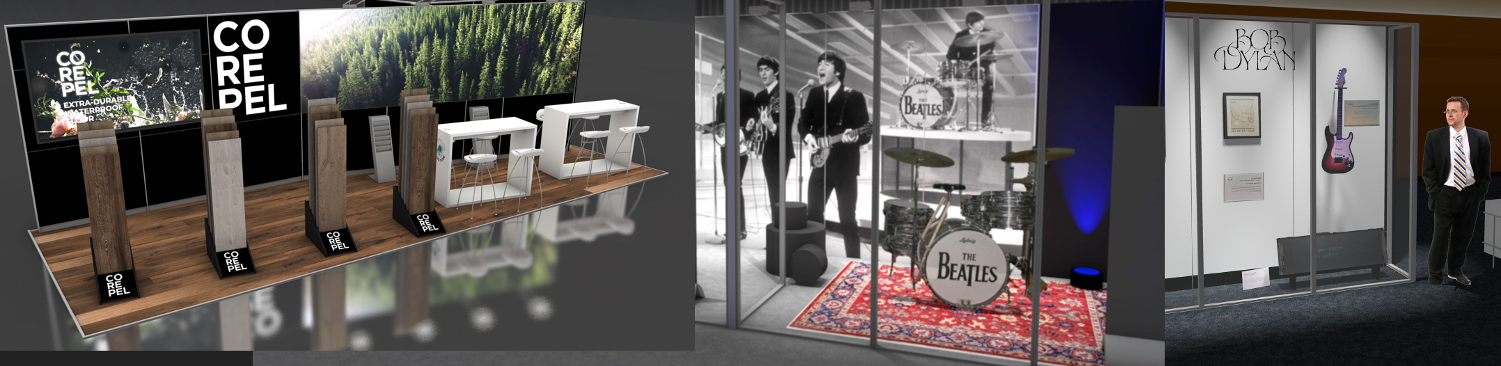
@michaelk This is what the doctor ordered ... Much appreciated ! (See attached) @Tom W. Please and Thank You - clue me in if this is what the Framing Member tool already does. Attached Example: Aluminum extruded frame components exists for graphic projects in Single and Double Face profiles. These typical 2D Symbols are show in opposite corners. (Green and Blue for clarification) - In the center is a Persp View of an Extrude Test Object. The Extrude Test.vso Plug In (above) allows the VW extrusion to be designed, (based on a 2D Symbol) and then the extrude / profile can be changed when needed, by selecting a different 2D VW Symbol from the OIP. Very Slick! Symbol naming Convention speeds the process - original location of the 2D Symbol, determines placement in the extrude, and therefore where a different 2D Symbol is located, if the intent (as demonstrated) is to have them swap out as though the design started from scratch. Thank You Again ! Peter Extrude from Symbol_1.mov -
VW_1 and Chief Architect Comparison ...
Elite Exhibits replied to Elite Exhibits's topic in Architecture
@bpsabatier & @TomKen Thank you for the informative feed back - it is greatly appreciated ... and for just taking the time to comment on the FORUM Peter -
A way to make a variable Extrude - ¿ Use a PIO ?
Elite Exhibits replied to Elite Exhibits's topic in Solids Modeling
@markdd Thanks much ... Need the Symbol Component, as that is what we Inventory by (Worksheet). My understanding: Blue Symbols, are no longer countable Symbols when they are placed on the drawing. (Please correct me if I am wrong on this assumption) Peter -
A way to make a variable Extrude - ¿ Use a PIO ? Intent is to have a series of pre drawn 2D shapes that equate to various in stock aluminum extrusions. Symbols would be created with one of the pre drawn 2D shapes Extruded, or Extrude along path. When needed, it would be great if there was a way to select a different one of the pre drawn 2D shapes and have the end result show a revised Symbol, without the need to Edit the Symbol, and edit the extrude inside. We already realize that the pre drawn 2D shapes can not be Symbols, as one is NOT able to extrude a symbol. Suggestions ? Peter
-
Script that changes Callout settings to match Text ...
Elite Exhibits posted a topic in Vectorscript
Script that changes Callout settings to match Text ... Callouts are easy to use in a worksheet - Text does not have the same ability (That I am aware of ...) The Callout settings often make a selection that does NOT represent the size of the text in the Callout The attached shows two similar groups, each with the Same Callout One has been manually adjusted to keep the selection size of the Callout in sync with the text it contains Question is: ¿ Is there a way to have the Callout settings in the OIP match the Text in the Callout ? Peter Callout Bounding Box.pdf -
Question: Anyone have experience or a comparison of VW and Chief Architect Comparison ? Peter
-
@grant_PD Question: ¿ Did you ever look at the texture and how it is mapped in the file attached above ? Peter
-
@grant_PD Interesting. I think VW should take note of ... (¿ How many times that could be said ?) Peter
