
Elite Exhibits
-
Posts
583 -
Joined
-
Last visited
Content Type
Profiles
Forums
Events
Articles
Marionette
Store
Everything posted by Elite Exhibits
-
Undo causing crashing Vectorworks 2023 SP4
Elite Exhibits replied to Heberling's question in Troubleshooting
FYI Sounds like symptoms when we first loaded 2022 last year onto an Intel McBook Pro (Previous employer) Ended up backing up to 2020 - for more stability Have recently loaded 2023 onto an M1 Max MacBook , yet to risk it based on a few large projects in process. Will let you know Peter -
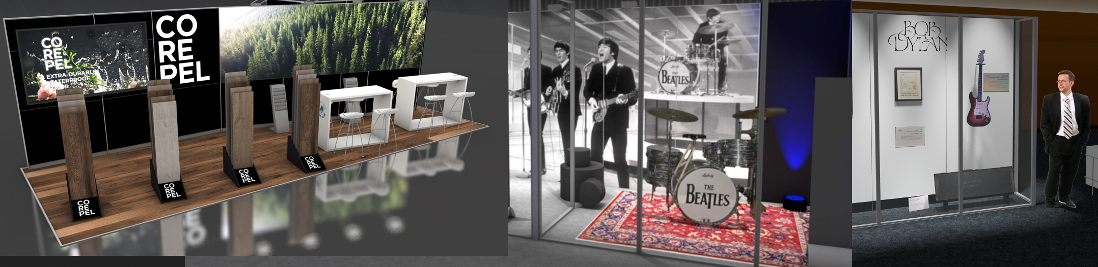
Mike The 2D/3D Hybrid Concept allows for the 2D component to be extremely simplified, making the drawing creation / editing process much easier. (ie: a simple 2D shape, like a rectangle, is easy to quickly select and position, compared to a complex 3D item it represents: a gondola in a store set up design for example. If your Workflow is akin to COLORFORMS, (Googler it ...) then 2D/3D Hybrid is the best method. Keep in mind, a big plus is that the Top/Plan view, when these 2D/3D Hybrid symbols are utilized, is already finished . With Legacy, or 3D Only applications, the Top / Plan needs to be rendered to create a coherent presentation. We use 2D/3D Hybrid as much of what we design is created from a stock set of components. (ie: 2D/3D Hybrid Symbols). The use of 2D/3D Hybrid symbols also allows for integrated information that is only seen in the Top / Plan view while the 3D component of the 2D/3D Hybrid is shown in the rendered perspectives. Color, text, size designation, etcetera. This happens automatically when switching views. Concept: Similar shape Items, could have assigned colors in the 2D component (...that only show in Top/Plan) to visually indicate variations in the associated 3D component. Likewise, text could appear in the 2D component, that is not shown when switching to a 3D view. This is a long standing (unique) automatic feature of VW/RW. Attached Example - Page 1, the 2D Top/Plan is simple with a plethora of information: Wall Heights are shown by color, graphics designated by pattern, furniture is easily understood as white, wood tone, grey etcetera. No rendering needed. There are no Viewports used or needed - No additional annotations for the Symbols, if the identifying text is part of the 2D / 3D Hybrid Symbol. The page 2 rendering (Same drawing as page 1 Top/Plan) looks very realistic, and only Open GL was used. (Shaded) FYI: The addition of the Component Edit Mode has reeked havoc with what once was a simple process for editing 2D/3D Hybrid Symbols in VW/RW - Not the creation of, Not the use of, Not the appearance of, but the editing. My 2¢ FYI Peter 311308738_2D_3DHybridExample_1.pdf
-
Fix editing within all container objects
Elite Exhibits replied to Kevin McAllister's question in Wishlist - Feature and Content Requests
PVA-Admin Assisting a person new to VW and suggested that they DO NOT use Paste in Place in newer versions of VW 2019-2023 - inside a container - (Extrude in this instance). They referenced this FORUM thread (Fix editing within all container objects. Yes, it is 7 years old...) when hunting for a solution. After my renewed tests to Paste in Place inside a simple extrude, I do NOT have a real solution. The PVA - Admin Comment 1) quoted above just does not provide any solution. In simple English: Do NOT use Paste in Place inside a container. It does not work as you assume it should. Paste in Place should be called ... where did it go ?!? - What is the real logic ? (an animated example may be appropriate here) Kevin, Andy, Zoomer, Maine all have great commentary above, (Thanks) though I feel a solution never appears. ****************************** Here is what is happening in the attached example. Existing design Top View Open GL Rendering Select simple Extrude Double Click to Edit Problem One Blank Screen Problem Two Nothing Selected (Where did it Go ?) Select All Zoom / Fit Problem Three Base 2D geometry for this extrude is rotated from the expected orientation Select single shape Cut Paste in Place Problem Four Dialog Box: Option to convert to Screen Plane (¿ Why or Why Not ?) When this shape was selected there was NOT a option in the OIP to alter / define Layer Plane vs Screen Plane (Or Working Plane, or 3D Plane or Extrude Plane for that mater...) Why is there NOW an option needed to alter its state ? Just want to put the item exactly back where it it visually came from. Default response (YES) is selected Problem Five Nothing visible Pasted in the current view OIP shows a selected item Select All Zoom to Fit Two Items Selected Several Meters apart (?) Select item outside the Page Boundary Zoom to Fit Problem Six Pasted object is yet again rotated from the previous and the expected orientation. ¿ The question here is Why this location ? So if Paste in Place will not function as desired / expected, then simply designate a location with a click of the cursor, and use Paste. (Then move the object back into position as needed.) Deselect All Select Item inside the Page Boundary Zoom to Fit + Zoom Out (slightly) Click in the drawing near by (This should be the location that the clipboard will paste at) Paste (ie: NOT Paste in Place) Again: Dialog Box: Option to convert to Screen Plane (¿ Why or Why Not ?) Default response (YES) is selected Problem Seven Nothing visible Pasted in the current view (Is Paste also malfunctioning inside a container ?) OIP shows an item selected Again, click in the drawing near by (Again, this should designate the location that the clipboard will paste at) Paste (ie: NOT Paste in Place) Again: Dialog Box: Option to convert to Screen Plane (¿ Why or Why Not ?) Change the response, NO is selected this time. Problem Eight Nothing visible Pasted in the current view OIP shows a Polyline selected Repeat one more time, just in case ... (¿ What is the difference ?) Problem Nine Again, nothing visible Pasted in the current view OIP shows an item selected Select All Zoom to Fit Paste in Place and Paste Objects are all out in space ¿ far from the original location it was cut from ? Keep in mind that this Drawing / Extrude / Item could be inherited from an old drawing / older version of VW/RW ... Problem Ten Workaround required to control this inexplicable anomaly Copy Item (Do Not Cut) Open a new drawing Paste Modify as needed Change to Screen Plane in the OIP Copy this modified Item (Do Not Cut) Change back to the original drawing Click in this original drawing (This should be the location that the clipboard will paste at) Paste (ie: NOT Paste in Place) Again: Dialog Box: Option to convert to Screen Plane (¿ Why or Why Not ?) Default response (YES) is selected, even though the item was set as a Screen Plane in the OIP ? The item is now Pasted Close to where it is desired Move / Rotate / etcetera to place as modified item as needed Original item is still at the expected location, it can be used as a reference to locate the modified shape. Delete original shape Exit Extrude ****************************** As a user of VW/RW since MiniCAD days, I would really like to understand the functionality of how 1)Paste in Place within a container should paste at the coordinates of the copied objects... fits into any work flow, when outside the container world Paste in Place is vastly different. Question: Is there a way to move the container to ...the containers internal coordinate system ? Answers & Advice Are Always Appreciated Film was made in VW2020 on an iMac Pro Peter 369189587_PasteinPlacedoesNOTworkinaContainer_1.mov -
My 2¢ In a previous life ... We used a custom numbering plug in that would allows us to place a specific symbol and indicate the number in this symbol. It was used to sequentially number Frames / Positions in a systematic trade show design plan view. Numbering could start with a user defined selection. The numbers were consecutive, so the user would simply - click, click, click, to place this symbol with the number being automatically generated. We could then add more symbols on the drawing for revisions, consecutively or not, with the restart number selected at any point - or the user could re number the existing symbols on the drawing, again with a user selected a starting point. As a quick test - see the attached - I altered this symbol (Wall#) in an old drawing, with a yellow triangle background (I have yet to try this - I am told, that there is a Numbering Plug In @ https://benghiatlighting.com/software/product/savvy-sequencer-2/ that you may want to explore) Peter Numbering Symbol_1.pdf
-
Under View Menu - up to a point, then newer versions it is an option in Legacy Settings (Preferences) Peter
-
On the subject of the Data Bar ¿ Is there a way to have the Z show in the Data Bar for a 3D object ? Answers & Advice are always Appreciated Peter
-
quick transition from design layers to sheet layers
Elite Exhibits replied to demetris ktorides's topic in General Discussion
FYI I use Saved Views and jump back and forth to the specifics set when I make the Saved View I have used this to go from inside (Edit Annotations) in a viewport, directly inside another viewport - when I want to copy and paste specifics for uniformity. I often use nebulous names like 111 & 222 then I am able to over write them as the needs arise Peter -
FYI I believe that there is a Set Attributes by Class plug in that might be helpful Peter
-
My 2¢ I go to edit a symbol and VW/RW shows me the symbol in Edit Mode, even though the associated Classes are NOT on. ...as Andy mentions, I turn on these classes - or ALL classes if I do not know which are needed - Depending on the situation, try the Visibility Tool Peter
-
Script to automate Worksheet options when counting Symbols ie: More Choices It is simple to make a Worksheet that counts all the symbols in a drawing - When there is a need to remove some specific symbols from the Worksheet, it is easy to select the More Choices in the Criteria, and select is not. (See attached - Green Arrow) Selecting the Symbols from the VW provided - non searchable - list is often the complexity. I have attempted to type the resulting string directly into the Worksheet Criteria. (See attached - Red Arrow) One needs to have a remarkable memory to enter the Exact Symbol names. (Example Symbol Names also attached) So ... . The request would be to have a script that lets one select Symbol... is not... and then select several symbols vs the addition via More Choices, , then More Choices, then More choices ... Etcetera Suggestions are welcome Peter Symbol Count Criteria_1.pdf Symbol Names_1.pdf
-
Change multiple viewport rendering styles with 1 Click
Elite Exhibits replied to Mat Caird's topic in Vectorscript
Mat Caird Did you ever end up with a solution - I stumbled into a CUSTOM MODIFICATION to alter all the Viewport Render settings at once ... It is simple, but it is NOT immediately obvious. Would love a worksheet where I am able to look at and review / change the Rendering settings and update the drawing vs When you have time - Thanks Peter -
Curious: Interesting difference in two similar items when comparing the fundamental shapes Both base Rectangles (...of similar size). In the OIP they have near equal numbers, except one has two additional entries Screen X: & Screen Y: - see attached ¿ Any clues from Anyone ? VW 2020 MacBook Pro Peter ScreenX Screen Y in the OIP.pdf Unable to Reshape Grouped Extrude_1 test.vwx
-
Ramon / Pat I am NOT the expert at this, but I believe that I have used the Stacking Order in a simplified TBB as Sheet Data Page Number (Attached) Maybe someone else will chime in to confirm ... Peter Sheet Data Page Number.pdf
-
Extrudes and solid additions don't have a 2D fill in Top/Plan
Elite Exhibits replied to JonKoch's topic in Site Design
Pat & Others ... What I am attempting to discern... ¿ How do you control the 2D attributes in an Auto Hybrid ? The 2D Appearance Dialog Box, would lead one to believe that the 2D Attributes of Contained Object(s) ie: the applied IMAGE would be visible, when selecting that option. The "HELP note" at the bottom of the 2D Appearance Dialog Box, (Large print giveth, small print taketh away...) appears to reference from which it was sectioned. (?) Assume this is based on the Elevation number and option. The traditional Hybrid has been an object that has an appearance in Top/Plan without the need to render, while potentially having a different appearance in 3D. ¿ Is the Auto Hybrid miss named in that it works in a Viewport differently than a Design Layer ? (a test Design Layer / Viewport look the same in Top/Plan...) If you edit the Auto Hybrid, and adjust the Attributes on the base geometry to look as desired, the Auto Hybrid does NOT show this alteration in the Top/Plan VIew (?) The IMAGE in this case. Peter -
Extrudes and solid additions don't have a 2D fill in Top/Plan
Elite Exhibits replied to JonKoch's topic in Site Design
Pat File attached ... (third auto hybrid) - Does the class you have assigned to the 2D and 3D parts of the auto hybrid have both a 2D Image Fill and a Texture assigned? - Affirmative Fourth option - Edit the AutoHybrid and assign a Texture to the Extured (...that is inside this AutoHybrid) directly from the RM (FYI - For simplicity, Purged attached VWX 2020 file and eliminated all except one IMAGE file) - Peter Auto Hybrid 4 Cubes Posted.vwx -
Extrudes and solid additions don't have a 2D fill in Top/Plan
Elite Exhibits replied to JonKoch's topic in Site Design
Tom W, thanks for the above clue - The magic setting that actually shows the 2D Cut Plane component of an Auto Hybrid, is... While the HELP file states: The auto hybrid’s settings provide complete control over its 2D display attributes, with separate, classed parameters for the appearance of the cut plane and extents below and above the cut plane. From what I worked out, (This example, is so an Image can be the 2D Top/Plan representation of the 3D in an Auto Hybrid...), set up the Image and the Class first, then assign this Class to the basic 2D geometry, then (for example) extrude the 2D geometry, then convert this extrude to an Auto Hybrid. Oddly, in this case, the original 2D object can be in one class, (This is what I refer to as the determining Class) the extrude in another class, and the Auto Hybrid in a third. This could allow the 3D component of the Auto Hybrid to be turned off in other than Top/Plan, while the 2D component still appears as expected when the drawing is in Top/Plan. That original 2D assigned Class (...what I refer to as the determining Class) sets up the 3D in that it is the Class assigned Texture in a rendered view and the 2D Image in Top/Plan View Example Attached: Upper 4 Auto Hybrids are on one Design Layer - Shown in an Iso View / Rendered Open GL - Lower 4 Auto Hybrids (Same 4 as above...) on a different Design Layer - Shown in Top/Plan View All 4 Auto Hybrids are in the same class. Left most Auto Hybrid has the original 2D component and the 3D component assigned to a different Classes 2nd Auto Hybrid has the original 2D component assigned to the determining Class and the 3D component assigned to a different Class 3rd Auto Hybrid has both the original 2D & 3D component assigned to the determining Class Right most - Same as #3 above, except the texture of the Extrude inside the Auto Hybrid, is applied direct from the RM, not via the assigned Class. Some of this is also available (?) thru the 2D Appearance Dialog - Possible that the 2D Cut Plane appearance is assigned directly with the Class Drop Down, though the Fill & Pen buttons may not change this selection any further. (Warning: Don't keep the Display Setting on 2D and the wonder where the Auto Hybrid went switching to a 3D view ... ) Peter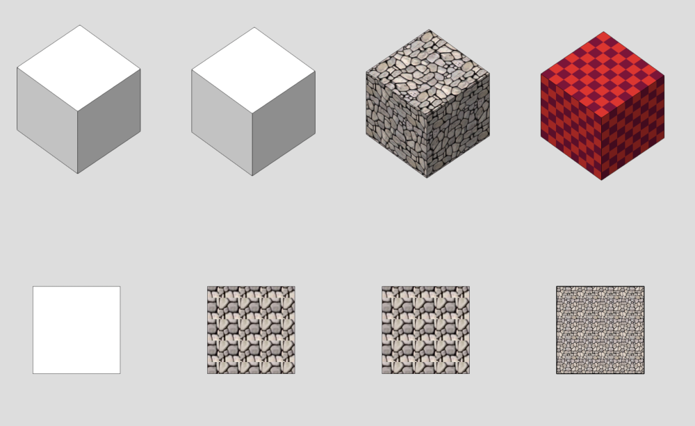
-
Marco I have had similar issues with VW/RW Designer 2019 - 2020 - 2021 - 2022 (iMac and / or MacBook Pro) Commented on and reported missing (¿ ie: invisible ?) items (Case 00270499) One suggestion: Turn the Unified View On and Off ... or maybe it is Off, then On (also check the settings) I do not use Unified View, yet I have seen it cause similar issues. Even when the file is a only, single Design Layer. Example: Edit a group - Extrude geometry is selected in an Iso / Open GL view (This is Indicated in the OIP) The selection handles show, but no object. Use of the Fly Over tool / Object Center Mode will reveal the geometry. Stop rotating and it will disappear again. Attached video show an example. This may also be a complication of the untested resuylts with the Component Edit Mode Peter 1841207929_UnifiedViewReappears_Dissapears_1.mov
-
Extrudes and solid additions don't have a 2D fill in Top/Plan
Elite Exhibits replied to JonKoch's topic in Site Design
Pat Thanks, Except it Doesn't ... Was attempting to show that an Image was the Attribute Fill on the Original (Converted) Object The VW/RW 2020 HELP file states: Uses the fill attributes of the original converted object(s) for the cut plane ... I am going to assume that Image fill does NOT work with Auto Hybrid, the way it does with a traditional 2D/3D Hybrid Symbol.. So it goes ... Peter -
Extrudes and solid additions don't have a 2D fill in Top/Plan
Elite Exhibits replied to JonKoch's topic in Site Design
Pat As always thank you ... (Same dialog as in VW/RW 2020 Except it does not work as expected - see attached ¿ Assume that the next comment is, only works with Attribute Fill Colors NOT images ? Not what I would think based on reading the HELP ... (Uses the fill attributes of the original converted object(s) for the cut plane) Peter Attribute Fill is Image Auto Hybrid.pdf -
Extrudes and solid additions don't have a 2D fill in Top/Plan
Elite Exhibits replied to JonKoch's topic in Site Design
Pat Affirmative - VW/RW 2020 Peter -
Extrudes and solid additions don't have a 2D fill in Top/Plan
Elite Exhibits replied to JonKoch's topic in Site Design
Question: So what is the magic setting that actually shows the 2D Cut Plane component of an Auto Hybrid the way the 2D component shows on a traditional 2D/3D Hybrid ... VW/RW Help states - ....Uses the fill attributes of the original converted object(s) for the cut plane or is it ...you have to do something if you want to have filled 3D objects show in Top/Plan view. Pure 3D objects will always show in Wireframe in Top/Plan. Created a Square (Screen Plane) Assigned an Image to it in the Attributes Pallet Looks as expected in Top/Plan Extruded it Assigned a similar Texture to the Extrude in the OIP In a rendered 3D View, Looks as expected Turned this into an Auto Hybrid Set the Cut Plane part way up the Extrude and checked: Use 2D attributes ... In Top/Plan view there is only the traditional Wireframe view of a 3D object, no 2D Plan View as expected with a traditional 2D/3D Hybrid. Making this Auto Hybrid a Symbol does NOT have the desired 3D rendered view and Top/Plan VIew appearance If I go back to the beginning and duplicate the 2D Square, then combine with the Textured Extrude, ...make that Symbol, it behaves as expected for a Hybrid in both a 3D rendered view and Top/Plan Views Suggestions are always appreciated Peter -
Preferences 3D Tab - Default 3D view Render Mode / View Projection
Elite Exhibits replied to Elite Exhibits's question in Troubleshooting
FYI July 2022 - Case number 00270325... Peter -
Preferences 3D Tab - Default 3D view Render Mode / View Projection
Elite Exhibits replied to Elite Exhibits's question in Troubleshooting
Pat A new drawing with a simple extrude and the 3D Render Mode ... settings appear to work as expected - Edit an older drawing and ?!#%@?! ... I gave up on getting it to work - Leave it set to Wireframe & Ortho. My comment above was from last summer on 2022. New employer and we have backed up to VW/RW Designer 2020 as it is stable. Based on what was/is happening, there may be two potential issues. Open GL / MacBook Pro or Unified View. Finding that Unified View causes a remarkable number of anomalies. Items disappear, Items selected, yet invisible - textures missing in edit group mode - items move while editing a hybrid symbol - rendering different in Open GL compared to Renderworks - etcetera I keep Unified View Off and only Display Screen Objects Checked - On occasion I needed to turn Unified View On to get things to behave. (Odd as this occurs when only a Single Design Layer is in the file. Ref: "What happened to 'Unified View' in v23?" Peter -
Question ? ¿ Is this a bit complicated ? - Try extruding several items at one time ... (See attached) Peter Multi Extrude.pdf
-
Kars Keizer ERROR message when I run the script above - Only for VW 2023 ? When you have time - Thanks VW/RW Designer 2020 - iMacPro Peter

