


Robert Anderson
-
Posts
3,233 -
Joined
-
Last visited
Content Type
Profiles
Forums
Events
Articles
Marionette
Store
Everything posted by Robert Anderson
-
Also, there is the new "Simplify Mesh" command on the Modify menu. This can do wonders for excessively tessellated meshes like the one you are showing...
-

Vectorworks and "Intelligent/Predictive" Tools
Robert Anderson replied to jmanganelli's topic in General Discussion
Hi Joe, and thanks for posting on this timely topic. I think that my answer to your question lies in the way we've implemented our algorithmic design tool, Marionette. Marionette is an open source design environment that is 100% Python based and can make use of any Python library out there. So any library that you need (NumPy, SciPy, Pandas, MatPlotLib, GeoPy, etc., etc.) can be downloaded and included. I don't think the power of this can be overstated. Sarah Barrett, one of our Marionette evangelists, has done a number of "infographic" Marionette definitions that you can see over at our Marionette page. Climate data, psychrometric charts, etc. Below is one of her popular ones that uses e.g. GeoPy. There are other advantages on using Vectorworks as an algorithmic design platform, not the least of which is the degree of integration that you can build between your BIM model and your algorithmic design functionality. Imagine a prototypical building that could be deployed across a region, and could optimize its sun shading and photovoltaic array automatically on each site. This can be done today using Vectorworks' Marionette tool. I'm working (as we speak) on a Marionette presentation for next month that I will vid-cap and share with the Marionette forum here. Look for it! Thanks again for posting and your kind words on Vectorworks.- 4 replies
-
- 1
-

-
- vectorworks
- predictive
- (and 3 more)
-
3d assets - sanitaryware
Robert Anderson replied to MRD Mark Ridgewell's topic in General Discussion
Vectorworks Architect has a fairly decent variety of sanitaryware that it ships with: Generic, American Standard, Artinox, Bette, Bradley, Duravit, Franke, and Kohler. We'll be announcing more manufacturers this fall plus you can use the BIMobject tool to download many more from that site. What manufacturer in particular are you looking for? -
Hi ptoner, Not sure I understand your question. When you convert an earlier-version Sheet Border to a Title Block Border, if the old border was locked to page center, the new one should be also. Look at the Sheet Border tab on the Title Block Border Settings dialog.
-
Vectorworks 2018 uses Object Styles to share Title Block resources: Take your converted title block as a starting point. Go to the Title Block tab and click the Convert to Unstyled button. Use the Edit Title Block Layout to change the graphics as desired. You can also add text and make field assignments in this context. Exit the layout, and now use the Styles pulldown in OI palette to save this as a new style. Once you've created the style, you can share the style symbol and incorporate it into your document templates as any style symbol.
-
John V, actually there are several templates available under the "New..." command. Take a look at the templates that begin with "BIM". These have stories (storeys) preset, and story-enabled wall styles as well.
-
Script - Adding text and adjusting attributes
Robert Anderson replied to Sadamo's topic in Vectorscript
Vectorscript and Python (and, for that matter, Marionette) are basically identical APIs. So factor one in choosing your API is, which language syntax are you more comfortable with, Pascal (which Vectorscript uses) or Python? The process you describe (operating on selected objects) is an analog of a manual process, i.e., it is the way you'd do it 'by hand' in the Vectorworks interface. What you learn as a programmer is that there are other (possibly more powerful) workflows that become apparent and give you a lot of flexibility. Just as an example, if I were going to perform a repetitive operation on a number of objects meeting a particular criteria (e.g. having a particular record,) I'd use a function called ForEachObject(). This allows me to establish a criteria ('find me all objects with the XXX record') and pass them to a process that modifies them (e.g. the FadeAndLabel() process). This is done using a data concept of "handles", which has no good analog in manual use of Vectorworks but is central to efficient use of Vectorworks using any API. Not sure about your last procedural item: "Convert objects to group". Do you mean group all the processed objects, or actually convert e.g. a plug-in object to a group? (The latter is a more profound operation, and might be considered 'destructive'.) Not sure what you mean by 'identifier errors'. Maybe you post a screenshot of an error alert on the forum. Good luck! R -
There is no direct import. Best to use IFC (for 3D / data) or DWG (if all you want is 2D).
-
Hi SunnyFIsher, Sure you can. In the "" tab of the Settings dialog, give the tags a particular class (I think there is a preferred class of 'Door-Spec' and 'Window-Spec' for this.) Then just hide that class in the viewport settings. HTH, Robert
-
Right now, the Vectorworks "Unfold Surfaces" command can do flattening only of simple (singly-curved) shapes. TouchCAD can do unfolding of complex shapes. (You'll probably have to convert your subdivs into other primitives before you export.) You can look here: http://www.touchcad.com/index.html
-
Hi, Adzm, The recommended technique for this is what we call "shuttle files". Essentially, you import the IFC to a blank file and then reference that "shuttle file" into your working file as a Design Layer viewport. I'm in a meeting right now and can't elaborate, but perhaps you can find something about this technique in the knowledge base.
-
Roof not viewing in Section Viewport
Robert Anderson replied to JR arch's question in Troubleshooting
Also check the class of the rectangle you used to draw the roof face. -
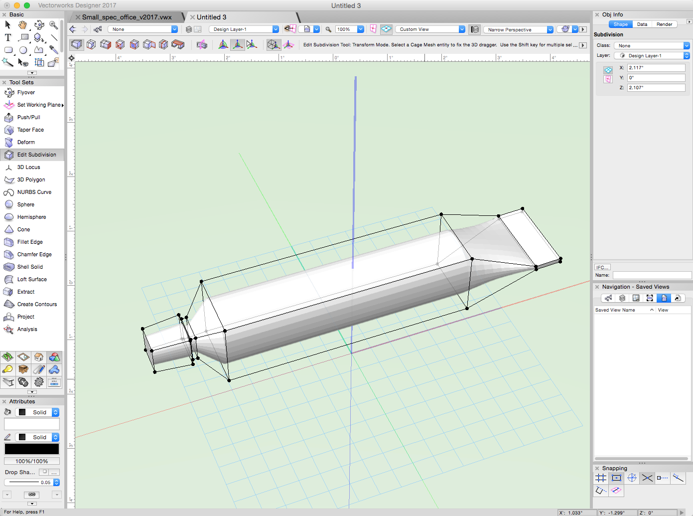
You can do this with lofts and a lot of patience, but a Subdivision Surface object (in later versions) makes this easy, editable, and fun...
-
Version 1.0.0
215 downloads
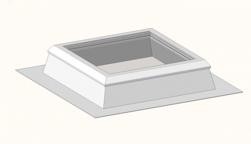
This Vectorworks file has a couple of variants of skylight object that are created with Marionette. The Marionette scripts for the skylights can be examined simply by double-clicking on the skylights themselves. This was my first attempt at using Marionette for parametric objects and I explored several topics: 1. The two skylight objects are different because one uses a simple set of parameters (height, width, curb height) to set the geometry, while the other allows you to pick from a predefined "catalog choice" on the Object Info palette. There is a Marionette node inside the second one that is called "Configurator' that takes advantage of a very useful data structure in Python called a "dictionary". For those of you interested in Python scripting, this is worth a look. 2. There are wrapper nodes inside the skylight objects called "Frame Profile" and "Curb Profile". These are essentially nested parametric shapes. Select either of these nodes and you will see a number of parameters on the OI palette. Double-click either of these nodes and you will see their internal scripts as well as a picture describing what the parameters mean. (You can paste anything you want into wrapper nodes as informal documentation.) 3. These objects write and maintain proper IFC data, including height and width, with every reset. -
Ah, so you're saying you want the Hyperbolic Paraboloid (HP). OK. (I wasn't sure, because the visual effect was so small.) If you want that, then I would loft a profile of beginning 'barn profile' to the end 'barn profile'. Then I'd shell it. Now you have your main shape. To get the frames, draw a number of extrusions across the 'barn shape' and do a model:intersect solids (using a duplicate of your barn shape). It's easier to do than to describe. I've attached a sample file. You are correct that you won't be able to get an HP using a roof face. Roof faces are strictly planar. HP_shell.vwx
-
Hi Christina, the two roof faces do in fact appear to be hyperbolic paraboloids. This is because the pitch at the beginning of the roof (let's say 'small end') and the end of the roof are not the same -- or at least it appears that way from your elevation. I'm not sure how you have modeled this. There are two general approaches to doing this: Approach 1: Use "pure" solid / 3D modeling. Make the closed shed shape in elevation, taper-extrude it, extract the outer surface, and shell it. Approach 2: Use architectural objects. Start with a roof plane. Draw it the way you want it in plan, set its pitch and play with its base-line to get the eave slope you like (you'll spend time in trial and error looking at this from various points of view). When you like it, mirror it along the sloping ridge. Then draw a couple of walls and use "Fit walls to Objects" command to get them to slope. You'll have to embed them in the roof objects to get the seamless look you want. The advantage of this approach is that you can use the Roof framer to get your rafters, etc. Good luck and check back in!
-
Stephan, most impressive. (I loved the fact that you had a Karl May collection!) Could one move examples from all the collections into a "general random" folder and get a truly randomized collection of books?
-
The Marionette icons are sized to work at 1:1 scale, if you have a large scale project, my recommendation is to have a saved view (at 1:1) that takes you back to the Marionette script.
-
One of the nice things about Marionette is that it's integrated into the design environment. This means that it can interact with the existing model. One example of this is shown in this example. This Marionette script looks for a Heliodon in the file, then draws a photovoltaic panel optimized for the orientation and latitude given by the Heliodon. The optimized angle is in a little wrapper node called "Tilt Optimizer". Challenge: It wouldn't be too hard to turn this one photovoltaic panel into an entire array of photovoltaic panels using the "Range" node found in the "Data Flow" section of the Marionette library.
-
This Vectorworks file has a couple of variants of skylight object that are created with Marionette. The Marionette scripts for the skylights can be examined simply by double-clicking on the skylights themselves. This was my first attempt at using Marionette for parametric objects and I explored several topics: 1. The two skylight objects are different because one uses a simple set of parameters (height, width, curb height) to set the geometry, while the other allows you to pick from a predefined "catalog choice" on the Object Info palette. There is a Marionette node inside the second one that is called "Configurator' that takes advantage of a very useful data structure in Python called a "dictionary". For those of you interested in Python scripting, this is worth a look. 2. There are wrapper nodes inside the skylight objects called "Frame Profile" and "Curb Profile". These are essentially nested parametric shapes. Select either of these nodes and you will see a number of parameters on the OI palette. Double-click either of these nodes and you will see their internal scripts as well as a picture describing what the parameters mean. (You can paste anything you want into wrapper nodes as informal documentation.) 3. These objects write and maintain proper IFC data, including height and width, with every reset. Enjoy digging in to these objects and post questions about these objects to this thread. skylight_demo-1(param).vwx skylight_demo-2[catalog].vwx
-
Dieter, Marionette scripts are strung together in a method similar to Grasshopper, Dynamo, Generative Components, etc. However the difference is, Marionette objects (called "nodes") are just sitting in the design layer. They create geometry there also. The script is associated with the results it creates so that if you modify and re-run the script, the old results are deleted and new results (geometry) take its place. BUT, you can also "wrap up" the script into a first-class parametric object (what we often call a "plug-in object".) By "first-class" I mean that the object can have parameters on the Object Info palette, and that it can (if you wish) be based on a path (poly, NURBS surface or other geometry). The difference is, a Marionette parametric object doesn't require installation in the workspace, because it always "carries its script with it", so to speak. You can put it in a symbol definition if you like and reference it to any project or share with colleagues. We are very excited about Marionette.
-
The entourage vehicles are hybrid symbols, which can't be rotated about the X or Y axes. What you should do is convert it to a 3D-only symbol, which can be freely rotated in 3D. (I recommend doing this on a copy of the original symbol.) Edit the 2D portion of the symbol, select all, then Cut. Exit. Now you have a 3D only symbol. Rotate it as desired. I'd like to know more about the "Double skins" you mention...
-
There's a script on the Knowledge Base: http://kbase.vectorworks.net/questions/1276/Reset+Wall+Peaks+Script
-
Vectorworks 2015 , 64bit and other technical questions
Robert Anderson replied to PVA - Admin's topic in General Discussion
Patrick, you will need to duplicate / modify wall styles to do what you want. I'm pretty sure. We are also introducing new templates for Architecture and BIM in the "New..." command. The BIM templates have some advanced (constrained) wall styles embedded in them. -
Vectorworks 2015 , 64bit and other technical questions
Robert Anderson replied to PVA - Admin's topic in General Discussion
I have to correct Jim on an earlier point. He said: The new layer-less story levels do not allow you to create multi-story walls that display correctly on all interposed floors. They DO create a lot of flexibility, and accuracy in modeling wall materials, and some over-lapping from one story to the next that was not possible before.