Robert Anderson
-
Posts
3,233 -
Joined
-
Last visited
Content Type
Profiles
Forums
Events
Articles
Marionette
Store
Everything posted by Robert Anderson
-

Link Text to Record Across Multiple Sheet Layers
Robert Anderson replied to ckrueger83's topic in Architecture
Is it safe to assume you're using Vectorworks Architect 2018? If so, all you have to do is make a "Title Block Border" style using that tool, identify which fields you want fixed (by project) and variable (by sheet) in that style, and you're off and running. More can be found here: http://app-help.vectorworks.net/2018/eng/index.htm#t=VW2018_Guide%2FSetup%2FConcept_Using_Title_Block_Borders.htm -
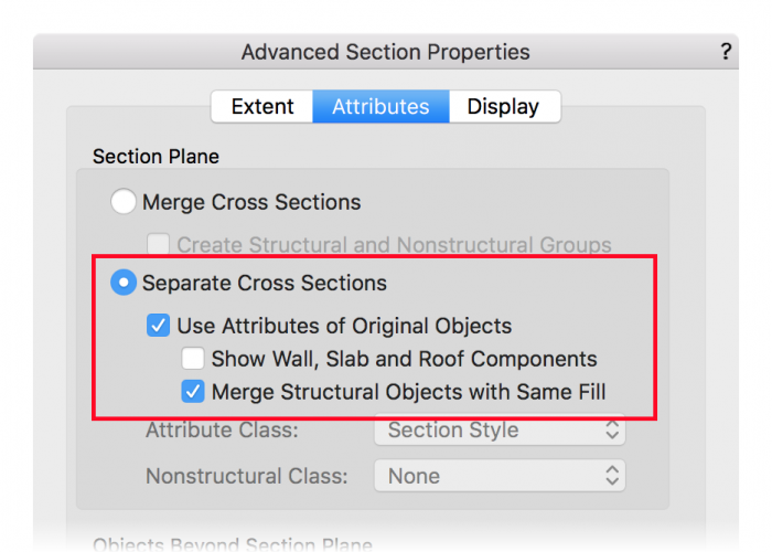
Hi Rcanhao, Try the following settings in the Advanced Section Properties dialog (see image below).
-
Hi, tjxj, Lineweights, arrowheads, hatch scaling, all those things that you have to do all the time in ACAD, Vectorworks handles for you. It is all about Layer Scale. What is Layer Scale? The "Layer Scale" used by VectorWorks comes primarily out of "WYSIWYG" drawing, pioneered on the Mac (and therefore part of Vectorworks' history). "Layer Scale" exists to allow graphic properties of the drawing or model to be represented properly, as though you were drawing at a particular scale on a piece of paper. It is a scaling value used to allow proper representation for PAGE-SCALED (as opposed to WORLD-SCALED) attributes: -Line weight; -Line style (e.g. length of dashes); -Marker (arrowhead) size; -Text size; -Hatch scaling; -Page symbol scaling; In "WYSIWYG" drawing, in order to properly display these attributes, there has to be an intended output scale so you can see how the drawing will look at that intended format. The practical upshot of all this is that you should set your "layer scale" to be the same as the predominant output scale of your project. This will necessitate the least amount of attribute-scaling in viewports. But in all design layers, at all times, you are drawing in world scale. An inch is always an inch, a foot is always a foot, no matter the "Layer Scale". "Layer Scale" serves only to set page-oriented graphics. Note also that you can scale some or all of these attributes in individual viewports as you wish.
-
if you are on a Mac and want to see invisible files, you can use a utility like Funter.
-
It looks like you are trying to insert the door object on the wall face. Insert the door in the wall centerline and use the "offset in wall" property to move the door to the face.
-
Multiple extrude may work, but is difficult to control for faces and faceting. Taper Solid should work. Subdivision tool likewise will work (and be very malleable!) The main advantage of the NURBS surface-to-shell approach is the easy control of getting a uniform thickness of the shape. (This may or may not be a requirement, though).
-
Create two vertical curves in the starting and ending profiles, use the Loft tool to connect them (this will create a NURBS surface), then shell the result.
-
If your file involves a large amount of imported 3D geometry, try going to the resources to simplify, particularly large or complex meshes, which can really bog down a hidden-line displayed viewport. Complex 3D meshes can be modified using the Simplify Mesh command. It has a preview so you can tune your simplification to be visually correct. If your file involves a lot of 2D imports from AutoCAD, often time very "deep" hatches or inefficient line styles can slow down the file. Try modifying these to simplify in the Resource Browser.
-
"one or more operations were aborted due to lack of memory"
Robert Anderson replied to Marsh's question in Troubleshooting
I can't answer that question, as I know very little about your specifics. You are running a 7-year-old application on a 5+ year-old OS. As projects grow in maturity, size, and complexity, sometimes you hit the wall. We don't like to see our users hit the wall. This is why we did a major re-engineering effort back in 2013 and 2014 to move Vectorworks to a 64-bit platform. Is there any way you can break the project into multiple independent files? This may be the only way for the short term. (I say "independent" because Vectorworks file referencing may not reduce file size nor memory footprint.) -
"one or more operations were aborted due to lack of memory"
Robert Anderson replied to Marsh's question in Troubleshooting
Please see the FAQ below: -
The bottom of the door opening should be at Finish Floor level. So, in the Story Level settings, set your Finish Floor and Top of Structure to the same level.
-
Are you using Fundamentals? If so consider upgrading to Spotlight or (alternatively) look at the ConnectCad add-on.
-
Referencing global orientation in a Plug-in Object script
Robert Anderson replied to Arshan's topic in Vectorscript
Hi, Arshan, You are certainly correct that it is crucial for a plug-in object to know something about its environment, not just its own local coordinate system. There is a crucial call, GetCustomObjectInfo() that gets a handle to the container of the current executing plug-in object. For experienced plug-in developers, it is usually the first or second call in the Main() routine of a plug-in. It returns: The PIO record name; A handle to the PIO parameter record; A handle to the PIO object (container) itself; and A handle to the wall (if any) that the PIO might be inserted in. With these handles, you can do things like find out where the PIO is using e.g. GetSymLoc() and the PIO's rotation using GetSymRot(). (Don't worry about the fact that these two calls say "Sym" instead of "PIO". They will work.) I recommend making http://developer.vectorworks.net/index.php/VS:Function_Reference one of the default tabs on your browser if you're going to start using VectorScript or Python to develop plug-ins. Best of luck, and let us hear! -
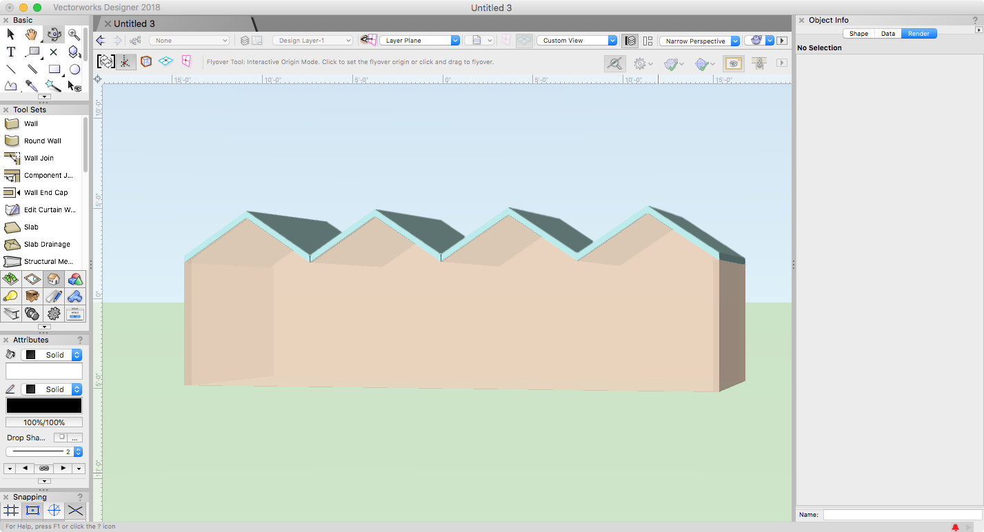
Draw the walls. Draw and position the roof objects. (I used four roof objects, but you could use an extruded zigzag or whatever). Select the roofs and choose "Fit Walls to Objects" from the AEC menu.
-
Shiyu, I had to look up "septated". Are you looking for something like this? This wall line is achieved using "Fit Walls to Objects" command.
-
Hi Shiyu, are we looking at a section here? When you say "in a closed room" do you mean this is a ceiling feature?
-
Marionette / activation - installation of marionette
Robert Anderson replied to ArnoXz's topic in Marionette
You can certainly use Python as a scripting language with the Vectorworks scripting API. See here . -
there's a super secret technique for this. (I'm pretty sure it still works..) In your MarioNetwork, draw a 2D locus over input ports that you want to hide. Let me know if this still works. (Sounds almost too simple to be true...)
-
Hi all, I thought that I'd try and put in one place some diverse Marionette resources for you who are new to Vectorworks' algorithmic / parametric modeling tool: Basic Tutorial in Vectorworks documentation More Advanced Tutorial in Vectorworks documentation Marionette on YouTube (thank you Jim) Marionette Developer Wiki (for Pythonistas)
-
Marionette can do procedural geometry like GH or Dynamo, but you can take this further and "wrap up" the geometry into parametric objects to use in your projects. Also, you can traverse the model by various methods (e.g. a query like "give me a list of all the masonry walls on the second floor") and perform operations, including querying and modification. Py knowledge is not necessary to use Marionette, but it will be very useful if you wish to create custom nodes, which almost any advanced user will want.
-
Vectorworks Architectural to read others Autocad files
Robert Anderson replied to Mark Pigott's topic in Architecture
You can import both Revit and AutoCAD files to use as backgrounds for your design. You can then add layers and draw additional information. If you are doing AV system design, you really should look at Connect-CAD, a plug-in to Vectorworks Architect. https://connectcad.com/ I think this could be a good fit for your needs. -
Take a look at your "printer setup" and make sure you have the "Scale" setting at 100%.
-
Yeah, I agree about the NIL handle thingie. Don't have time to search the VS Function Reference, though...
-
Pat, to get the handle to the default object or tool settings record, I think you don't pass a NIL handle, instead pass a handle obtained by GetObject() and the universal name of the PIO or command. For example, to set the default top shape of a door to a Gable, use the following one-line script: setrfield(getobject('Door'),'Door','TopShape','Gable'); HTH.
-
Clicking existing callout changes to random angle
Robert Anderson replied to Sue C.'s question in Troubleshooting
Were these callouts placed in Rotated Plan mode?