Robert Anderson
-
Posts
3,233 -
Joined
-
Last visited
Content Type
Profiles
Forums
Events
Articles
Marionette
Store
Everything posted by Robert Anderson
-
Hi antonf26, Do you mean you want the text size of the scale bar to change? The scale bar itself, of course, is necessarily drawn at world scale. The actual disstances and markings on the bar ought not to change!
-
 ThreeDot, that is true, if you want to dimension in an isometric view. You will need to use planar graphics and dimension on the cardinal planes. But anything projected onto the sheet plane can be dimensioned, of course, 2D or 3D.
 -
Version 1.2.0
58 downloads
Added an Image Scale factor, just to aid tweaking.... -
Font sizes for dimensions / note objects can be set in Advanced Viewport Properties. I do not know the effect on witness lines. A good general rule for dims and notes is this: If the dims / notes show up on more than one sheet, then they belong in a design layer (and may require a class to control their visibility). If they show up on only one sheet (as in e.g. a detail view), then they belong in the Viewport annotations, which are instance-specific to the viewport.
-
Version 1.0.0
26 downloads
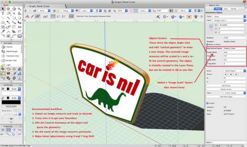
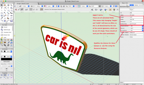
This is a path-based MariObject that creates a panel with image graphics. Can be used as a wall hanging, etc. The boundary can be any shape. The object scales an image resource to fit the control geometry. Also, it attaches a record that reports on area, overall height and width, etc. NOTE: this is all standard Marionette nodes, but uses a Fill node that is not standard (at least until next service pack). I found some bugs in the script of that node and we've got them in the buglist. -
Hi Julian, not sure why this is happaning. Make sure you are in Top/Plan and not Top view.
-
The most straightforward way to do this in Vectorworks is using Classes (e.g. Existing to remain, Existing to Relocate, New Construction, Demolished, Relocated). Give each class a separate set of class attributes (e.g. for US standards, Demolished would be no fill, red dashed lines) and set them all to Use on Creation. Then just assign these classes to your walls / doors / windows / slabs / etc. as you go. You can also use class overrides in viewports to handle additional visibilities. Then a set of saved views / viewports covers the various phases: Existing conditions: Existing to Remain, Existing to Relocate, Demolished visible and class-overriden to look the same. New Construction, Relocated hidden.) Demolition Plans: Existing to Remain, Existing to Relocate, Demolished . New Construction, Relocated hidden.) Construction: Existing to Remain, New Construction, Relocated visible with differentiating class attributes. Demolished and Existing to Relocate hidden.) Not rocket science, but it covers 95%+ of conditions. You seem to ask not so much about "Renovation phasing" but about phasing in general (Concept, Planning, Construction). These are not so much construction phases, as they are phases of increasing design development (at least I infer this from the names). I'm pretty sure that if you wanted you could use Classes in a similar way here.
-
coloring symbols background depending on database value
Robert Anderson replied to Arb's topic in Marionette
I think the approach would be to assign the colored boxes to a special class that is used only for that purpose. Then your Marionette command script could start by deleting all (old) objects of that class and re-run. The other approach is a little different, and it allows automatic updating, but a change in workflow. In this approach, you would make a Marionette plug-in object that incorporates both the symbol instance and the colored background, and it reassigns colors based on the record value. The problem with this is that I assume you want to work from existing drawings, i.e. existing layouts of symbols. I think the first approach would be more practical. BUT... (and it's a big "but"...) I would be doing you a mis-service if I didn't also mention Live Data Visualization. Built into Vectorworks 2020. If you're a Service Select customer especially, you will be able to do what you want to do without scripting. -
coloring symbols background depending on database value
Robert Anderson replied to Arb's topic in Marionette
The problem here is that you seem to be asking Marionette to do something that Vectorworks itself cannot do, and that is, to color symbol instances based on class. All instances of a symbol are 100% reflections of the symbol definition, including class and attributes. I think what you want to do can be achieved using Marionette, but you'll have to think about this particular limitation. You could for example draw a box behind each symbol in the desired color based on the symbol size, the symbol location and the value of your database field. That's pretty straightforward, but you'll have to think about things like -where- to draw the boxes, etc. -
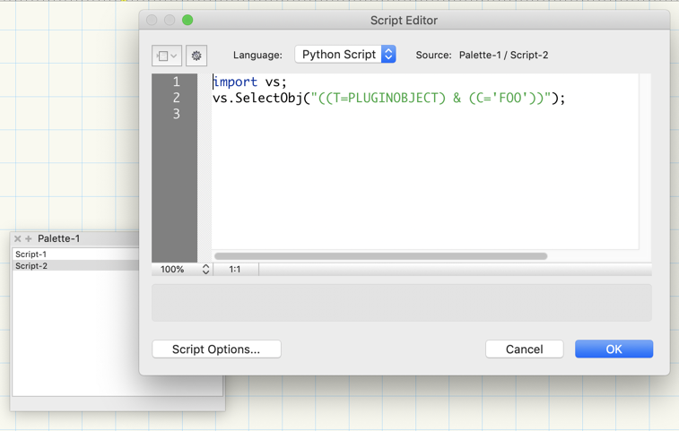
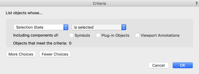
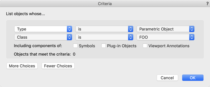
Hi arquitextonica, As to your question, "I have the feeling coding will be required to "complete/fine tune" the capabilities of the nodes, am I right?", maybe or maybe not. It depends on what you want to do. I think the secret of using Marionette effectively is knowing how to leverage your knowledge of the Vectorworks API. I kjnow you're new, but this will come with time. You speak of a filtered list of objects. The most efficient way to do this is (as I suggested earlier) using Criteria and the Objects by Criteria node.This is extremely flexible and powerful. Look here for more about Vectorworks search criteria. Foe example, suppose you wanted a list of all plug-in objects that happened to be in class "FOO". You could write the criteria to do this from scratch, but there's an easier way, and that is to have Vectorworks do it for you. You can do this using the Custom Selection... command to create a Python script that you can then copy and paste the criteria string from the Script Editor dialog to be the input in your Objects by Criteria node (select the node and paste into the field in the OI palette). See the screenshots below. You can use this technique to build filtering of virtually any complexity. Without breaking a sweat. If for example you wanted to operate only on selected objects, well, there's a criteria for that: SEL = TRUE will let you operate simply on selected stuff: To respond to your second question, I'm not sure what you mean by "generate a quick list of numbers". Can you elaborate on what you are trying to do here? Are you wanting a count? What "numbers" are we talking about?

-
Hi arquitextonica, Welcome to Vectorworks and Marionette. The key in doing successful customization is, as you correctly imply, knowing the right data structures and workflows to get done what you want. This may sound obvious, but is really anything but. For newcomers especially, there can be pitfalls. As an example, the Object Name field where you want to write the data has its own namespace, and all entries are required to be unique. You may (even probably) won't find this a useful constraint. So one way to think the process is, inputs and outputs. Inputs: where is the data coming from? The class of the object, an object name, an object property or location, a user dialog, even (gulp) a web page? (You can conceivably do all these); and Outputs: where is the data going? An existing object property, an IFC property, a new record field you want to attach, a class? I think the mandated-uniqueness of the Object Name removes it from contention. But that's just me. To generate the list of objects whose data you want to alter, use the Objects by Criteria node. Very simple. To read and write classes, and record and IFC data fields, use the nodes in the "Records & IFC" folder in the Marionette library. You've asked for not too much hand-holding, and I respect that. But feel free to ask if you get frustrated. This is a straightforward task (and well chosen for a learning project because it's about traversing objects in the drawing.) regards, Robert
-
From a blank document (with only "None" and "Dimension" classes), do this: Open the Classes dialog from the View bar button or the Organization dialog tab; Choose "New..." In the dialog that opens, choose the "Import Classes" radio button. In the pulldown at the top of the list, choose VW Arch (Imperial).sta In the list, choose an entry and hit command-A to select all Click OK You should now have the Vectorworks Standard Architect classes created in your file. You can save it as a template.
-
What about the standard Vectorworks (as opposed to Vectorworks UK) system? It's pretty basic and straightforward. Have you talked to support at Design Express about this? They may have some templates also.
-
When you say, "I need a class naming template that will correspond to ISO", I'm afraid that doesn't narrow it down very much 😀. Can you provide a little more information as to what you are trying to do?
-
I can't edit Records in the OIP like I used to
Robert Anderson replied to hihosilvey's topic in General Discussion
Try hiding the Nav palette. -
I can't edit Records in the OIP like I used to
Robert Anderson replied to hihosilvey's topic in General Discussion
I"m guessing here because I'm a Mac user, but I'd bet the field-list part of your Data tab is hidden. Point at the bottom of the "record formats" list area and drag up. -
buying vectorworks fundamentals online?
Robert Anderson replied to Kristell's topic in General Discussion
You can start with a 30-day trial from CADTEC to get going: http://www.cadtec.com.br/index.php?redirect=http://www.cadtec.com.br/internas/vectorworks/ -
When you placed the truss symbols, they include several classes that come in to your document along with the content. Turn off the class "Rigging-Truss-Simplified" and the masking rectangles will be hidden to expose the full glorious truss geometry.
-
Sean, I'm trying to understand the workflow you are trying for. The Detail Callout by definition is a region (polyline, if you will) of a drawing that is linked to the crop of a viewport. So not having a region seems to be kind of beside the point. What is your arrowhead pointing at?
-
Export multiple site models into an IFC file
Robert Anderson replied to aheimann's topic in Site Design
Glad to help, Anna. Often when default conversion resolutions are set to "high" or "very high" and you are importing spline data for topos, it's possible to get topographic geometry that can have 3000 or 4000 vertices for a single topo line on a feature. The site model works with the data it has, and doesn't simplifiy. This can bog down the model and also anything that depends on the model (like IFC export). You can reduce the vertices by a factor of 20 (and speed up by MORE than a factor of 20) with no discernible difference in the visual quality of the site model. That's why we have "Simplify 3D Polys" in the Terrain menu. Again, glad to help! -
Is there something like dynamic blocks in Vectorworks
Robert Anderson replied to mvandercruyssen's topic in Architecture
Thanks, Pat! -
Is there something like dynamic blocks in Vectorworks
Robert Anderson replied to mvandercruyssen's topic in Architecture
No problem. You create a Record format with a popup field containing the desired text values. Now you create a symbol definition with a piece of text that will show up with each instance (each insertion) of the symbol definition. Next you use the "link text to Record" command to get instance-specific text. -
Export multiple site models into an IFC file
Robert Anderson replied to aheimann's topic in Site Design
How big is the file in Vectorworks? Can you post a copy of the VWX file? -
Export multiple site models into an IFC file
Robert Anderson replied to aheimann's topic in Site Design
What version of Vectorworks? -
Export multiple site models into an IFC file
Robert Anderson replied to aheimann's topic in Site Design
What version of Vectorworks are you using to export, and are you exporting to IFC 2x3 or IFC4?