scottmoore
-
Posts
673 -
Joined
-
Last visited
Content Type
Profiles
Forums
Events
Articles
Marionette
Store
Everything posted by scottmoore
-
I would really like to see some improvement in rendering directly on the design layer using Renderworks. For the longest time this worked exceptionally well. Over the past several years it has become buggy and unpredictable. Interestingly enough, the common response is “you shouldn’t render directly on the design layer. You should use a viewport on a sheet layer.” Frankly I find that a terrible solution. Of course I use sheet layers to output designs but during the design process? What a huge waste of time and it completely takes one out of the design head space. If you want to see how that new texture you created looks, or check the lighting you just added, you should simply start rendering. Since you are probably centered up on the item you want to evaluate, you only need the render to run for a moment and then cancel it once you’ve seen what you needed to see. The idea that you have to create a viewport and then set your rendering and lighting options and then render it from a sheet layer seems an absurd workaround. The render bitmap tool is not much better. You have to wait for entire thing to render before it displays anything. If you set the dpi to something slightly better than 72dpi, so it looks halfway decent it takes far longer. I get that I only should draw out the bitmap to the size I need to see, but it still takes longer than a quick keystroke to start a render. Rendering on the design layer used to work great all the time. It would be really helpful if that were the case now.
-
The trick is to simplify the geometry to give you enough detail to know what the item is but not so much that it ruins your processing. Avoid curves, arcs, circles and all the connection fittings. If you need that level of detail then create two versions, one simple, one detailed and class them prior to creating your symbols. That way you can choose the level of detail for output purposes.
-

Extrude along path not working 'as expected'
scottmoore replied to hollister design Studio's topic in General Discussion
I often find that I have complicated paths that I just cannot get the correct result in an EAP process. Items like compound curved paths in three dimensions. My solution has always been (after a few attempts anyway) to divide the piece up into useable sections and then perform the EAP process. Typically that means I am creating the objects in a similar fashion to how they would be created in the real world. Often that process is quicker than trying to make the entire EAP work correctly. -
Working on a project file and I find that I am constantly switching back and forth between Imperial and Metric dimension standards. No worries with that, I do it all the time as we Americans cannot seem to wrap our heads around the far superior Metric system..... I have an annotated sheet layer where all the dimensions, which were absolutely created in an imperial standard, have changed to metric. Changing my document preferences back and forth, re-loading the sheet layer and even re-loading the file did not help. The only solution was to open the annotation and and manually reassert the dimensional standard in the OIP. According to Service Select, this is not normal behavior as dimensions should always follow the standard with which they were created regardless of user preferences. Checking with other users of the file, the dimensions were indeed imperial. Has anyone else seen this behavior?
-
Also, saved views don’t have to save the page (screen) orientation. You can select your first saved view on either your laptop or descktop, orient the view to your liking; perhaps by selecting the sheet outline and executing cmd+6, and then all your saved views will be correct regardless of the device on which you are working.
-
3D geometry invisible in Ampeg Vectorworks Library File
scottmoore replied to ajpen's topic in General Discussion
Here you go AJ. I added the 4x10 cabinets. Edgelightrgb_Ampeg.vwx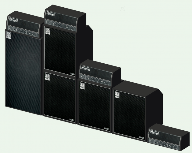
- 11 replies
-
- 2
-

-
- 3d geometry
- missing
- (and 2 more)
-
Favorite/Most used shortcuts?
scottmoore replied to hollister design Studio's topic in General Discussion
Cmd + A then Cmd +6. Find anything that ended up some odd place in a hurry. -
3D geometry invisible in Ampeg Vectorworks Library File
scottmoore replied to ajpen's topic in General Discussion
Well played AJ, well played! much appreciated by the way. An Ampeg 4x10 should go on my list for sure. -
As mentioned, I recommend using the symbol method for title blocks. Works like a champ.
-
3D Printing - Mesh versus Solid/Generic Solids
scottmoore replied to MaleXLR's topic in General Discussion
I don’t know that I can answer your question per se but I never convert my print files to mesh. I add and subtract solids a lot! always export to STL at the highest resolution and it seems to work quite well. -
3D geometry invisible in Ampeg Vectorworks Library File
scottmoore replied to ajpen's topic in General Discussion
Or you could check out my backline symbol library at edgelightrgb.com. ok sorry, it’s a shameless plug, but you won’t have that particular issue. -
Ben, Those fixtures are really cool! I doubt that there is anything like this in the existing library but perhaps I am wrong. I think these would require you to model them. Ideally the second unit would be a plug in object where you could adjust all the angles parametrically. It depends on how accurately you need your control to be as to how complicated it would be to make these.
-
I don’t know that I agree with your last sentence but I agree with all the rest of it. It’s often good practice to model detailed and specific items in a clean file where one can absolutely track any classes you are adding. It’s not entirely necessary, but it can become a real issue when you create something inadvertently on an incorrect class. I think it is ALWAYS good practice to insert someone else’s model into a clean file to fix it up.
-
While not difficult to simply model spansets or Gacflex, I tend to think you would have to physically wrap a specific unit around the specific truss and then measure the outcome. You could mathematically calculate the resulting length and probably be close enough, but not as accurate as physically wrapping a truss. You also would want to consider just how accurate and realistic you want your wraps to look. Do you really need curved surfaces and realistic looking straps? You can do that, and even put the labels on them, but those become things that slow the program down. I created mine as pretty simple geometry and added a miniature “target” in 2D to line up with the rig point and a piece of text detailing the truss size, type of wrap and height of the hook above the lower chord so I know where to place a hoist. All that hides beneath a rig point symbol. That, of course, does not take into account any BraceWorks functionality.
-
It’s funny, but a colleague of mine and I were just talking about upping our section view game. I think this solves most of that. Brilliant!
-
That is a brilliant idea!
-
After looking closer, I’ll walk back my comments about OpenGL. It does work quite well for my usage, but I wouldn’t use it for detailed section views on architectural plans. For my purposes I need vendors to see how items fit together and get a handful of dimensions and call out text blocks and OpenGL works great and looks somewhat artistic, but not really for detailed architectural work.
-
I am not entirely sure off the top of my head as all my symbols follow a similar line weight preference. Worth experimenting though. I will say a decent SL DPI and ambient occlusion are what make OpenGL worth using.
-
I’ve started to transition away from hidden line renders in favor of OpenGL for most of my drawings. If there is a really close detail, I’ll use hidden line but otherwise, I find the performance and results are better using OpenGL; at least for my purposes. When doing this my sheet layers are set at a minimum of 300dpi, textures and colors off, shadows and lines on, and ambient light set to 100%. Once VWX added ambient occlusion to OpenGL, it was kind of a game changer. That’s just me though. if I were doing straight up architectural sections I would probably still use Hidden Line.
-
Magic Panels/ Magic Blades / Pretty Lights.....Individual bulbs.
scottmoore replied to bronski14's topic in Entertainment
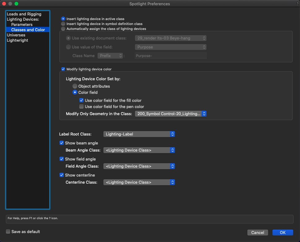
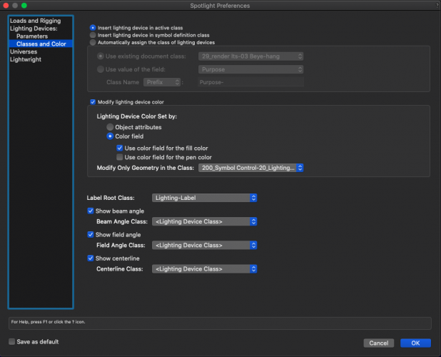
Here is an image of some lighting symbols using more realistic lenses. These are all my proprietary symbols, however, this is easily enough achieved with spotlight symbols as well. You will need to add a class to the standard set of spotlight classes for the lenses. I perhaps suggest calling it "Lighting-lens". In each fixture you can edit the 3D component from the Resource manager. Once in the edit window, click on the body of the fixture. The body of the fixture should be grouped so double click on that to now edit inside the group. In most cases a fixture will have a physical lens in the model so you should be able to select that. Once selected, you can add a texture to it as I have done and that texture should have a glow shader included and receive its color by the object fill (see below on creating those textures). You will also want to move the lens to the "Lighting-lens" class. Then exit the group and exit the symbol. In the FILE menu, drop down to "Spotlight Preferences". Select "Lighting Devices: Classes and Color." In the middle of the resulting pane turn "Modify Lighting Device Color" ON and then select "Lighting device set by color field" which means that the lighting device will respond to the color filed in the Object Info Palette or by directly editing the lighting information for that fixture. Select "use color field for the fill color" because we are wanting to basically change the fill color of the lens object. Finally select, "Modify only geometry in the class _________________ which is where you input your personal lens class. Note that my class is specific to my workflow so that will not be something that shows up in your file. So now the color filed for that fixture will modify the lens class for that fixture and the result should show up on your lens. As to creating the textures, I just snag a screen shot of a lens that I find online and make sure it is cropped nicely. - Create a new texture - Upload your image file in the COLOR shader. VERY IMPORTANT! Make sure that under the "Filter Color" pane that select "Use Object Fill". Once you do all of the above, Spotlight will adjust the fill of the object (the lens) based on your selection of color for the fixture. When the lens class changes, it will need to change the texture as well and this is the functionality that allows that. Very useful for any number of other things as well by the way. - Under the REFLECTIVITY shader, select GLOW. I would suggest an output of at least 100%, however, much higher than that will cause your colors to bloom. You can decide wether or not you want the texture to emit light. Frankly I turn that off just to keep rendering as efficient as possible. - Set the SIZE of the texture to the. size of the actual lens you are emulating. This will save time mapping. - Lastly, MAKE SURE that under the SHADOWS pane you turn off BOTH cast and receive. The way Spotlight fixtures work, there is a light source placed back and the yoke location and it has to shine THROUGH both the fixture and the lens. If the texture is CASTING a shadow, that basically means it s like throwing a piece of sheet metal where your lens is supposed to be. Not good. I hope that helps.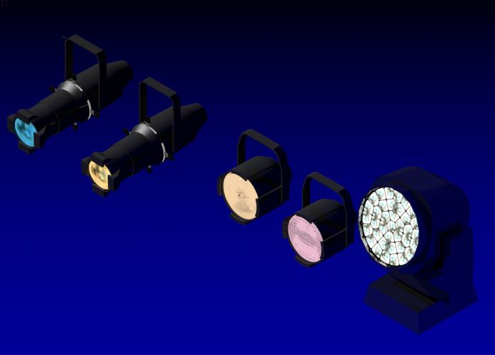
-
Magic Panels/ Magic Blades / Pretty Lights.....Individual bulbs.
scottmoore replied to bronski14's topic in Entertainment
I’ll scrounge up some images for you. To my knowledge, there is no new “magic” in the VWX department, though the ability to do this has been available for years. -
Kind of late to the party. All of the above suggestions are good ones. Indirect lighting (multiple bounces” makes a huge difference in the appearance of renders. Not having all the walls to reflect off of will impact the overall look. Otherwise, spending time adjusting light levels, possibly selecting various ies files, is critical. It can take a while to get right but usually worth the effort.
-
markdd "Something rather lovely about that lone shaft of light." Mies van der Rohe was correct in his assertions.
- 54 replies
-
- 1
-
-
- volumetric
- rendering
- (and 2 more)
-
Interesting view of an IES file in volumetrics just for the sake of conversation. This is one light source with all other ambient light off.

-
Just an update on the processes discussed in this thread: - Volumetric control has not changed at all which is not overly surprising but certainly disappointing. - The beam origination issue has not changed in Spotlight lighting devices. I am not really sure we should expect to see changes there either until there is some entirely new processes put into place. My solution is using my own lighting fixtures for presentations only. They are not "legitimate" lighting fixtures and have no records attached. That said, I find VWX performs really well and does not get bogged down at all when using standard geometry and not a bunch of plug in objects and symbols with records which has improved my overall attitude and sense of well-being whilst working in VWX. 🙂 But that is just for my in-house usage. - VWX did seriously step up their game in 2021 with the advent of vastly improved focus options which was part of the wish-list on this particular thread. My assumption is avoiding focus points as much as possible will improve the overall performance of the platform. Of course, now that I seldom use Spotlight lighting devices it's not that big a help to me personally, however, someone was indeed listening and I seriously appreciate that. Hopefully that is a marvelous improvement to others. - I have messed about with using IES files for lighting renderings and they can be useful to an extent in volumetric renders, however, performance is seriously degraded as there is a lot more detailed information that the CPU has to render. I find they might be best used for large format wash lights such as multi-cell 4-light, 6-light, 8-light units perhaps? None of this solves the "inverse square law" (as I jokingly refer to it) where the beam is basically computed as a piece of geometry; the larger it gets, the brighter it gets as there is more of it for lack of a better explanation. Continue on my friends.
- 54 replies
-
- 4
-
-
- volumetric
- rendering
- (and 2 more)