scottmoore
-
Posts
673 -
Joined
-
Last visited
Content Type
Profiles
Forums
Events
Articles
Marionette
Store
Everything posted by scottmoore
-
Sweet!
-
I ran into the “zip cord wrapped around the prongs of a PAR 64 rig” Over 200 PAR 64s each with an individual 18g piece of zip cord. I later peeked into the dimmer racks and found the incoming power was just bundles of zip cord to each pack. Ran an entire show off of two bus generators in a blizzard once....
-
My high school had red, blue and white border lights (remember roundels?) controlled by circuit breakers. Ugh. Now, can we get Spotlight symbols for Kliegl Bros and for Major fixtures? I’ll expect to see some dry rotted asbestos leads on the 3D portion.
-
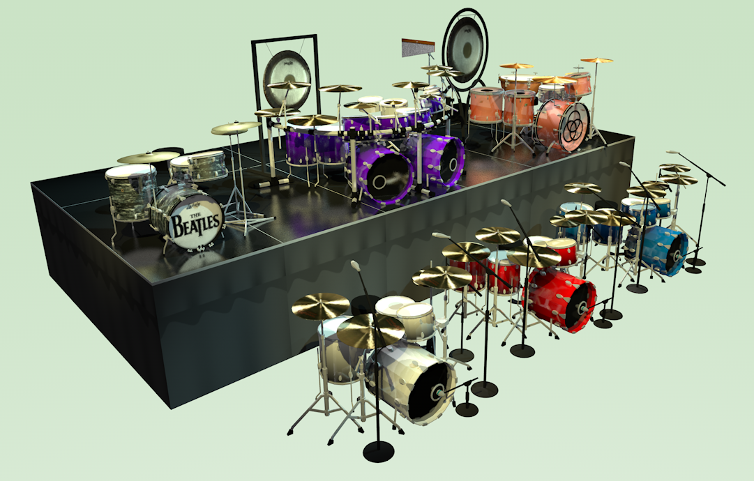
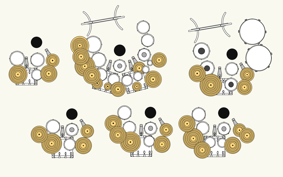
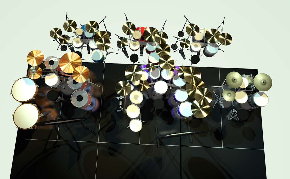
Thank you guys. I have created a substantial library of standard musical instruments (keyboards, pianos, drums, percussion, amplifiers and guitars that fit this same profile. I could spend a bit of time cleaning up line weights and sell a package if people are interested.
-
Just for fun I thought I would post some screen shots of the symbols (and cymbals for that matter) I've made for this purpose. All 3D elements are pretty simple. All circles are 12 sided polys, and hardware are all 4 sided polys which minimizes render times significantly. All are accurately sized. The finish on the standard kits is a white fade and it is set up so that I can edit the 3D component and select any shell which will select all of them in a group, change the color in the attributes menu and you can immediately change the color of the entire kit. These are the things I do when I need a break from real work....


-
Another consideration would be to use a Design Layer Viewport. Draw the turntable and all associated scenics on a dedicated layer and then Viewport that I to your Design Layer. Create classes for each necessary iteration of the turntable. Assign the viewport to the appropriate class. Then duplicate the viewport and for each iteration and assign those to their appropriate classes. The advantage is that you only have to manage a single drawing set and the editing of those drawings is as simple as editing a drawing and not having to go into editing symbols. That said, I usually create scenic elements as hybrid symbols so that I have a nice element to display in plan view. In this scenario you only need to address specific scenic elements as symbols and not having to turn the entire turntable into a symbol. Once you get used to DLVPs you will find they have a lot of functionality besides a “workaround” for angled lighting positions.
-

Vision & VW Design Layer Viewports
scottmoore replied to LJ TMS's topic in Vision and Previsualization
Agreed. -
Vision & VW Design Layer Viewports
scottmoore replied to LJ TMS's topic in Vision and Previsualization
LJ, Understood on all counts. I suppose the “hope” would be that you wouldn’t be exporting into Vision until all the design and re-design is done. Of course we never live in a perfect world and it may be that Vision will reveal some issues that need to be resolved back on the drawing board. It seems like the quick solution for Nemetschek would be to make the rotations of groups of objects in Vision very simple. The way I recall dealing with moving trusses (it’s been several years for me) was to import everything associated with the moving truss at one time before importing anything else and all those items became a “node”. Perhaps it was called something else but you get the idea. Regardless, you could easily grab an entire node and manipulate it. Once I understood that, automation processes were really quite simple; it just required multiple exports from VW > Vision. I am just wondering if that might be a faster workaround if rotation functionality works for entire nodes? Additionally, I don’t recall Vision having really accurate CAD control of any type so I would probably create some dummy markers in VW and export those into Vision to allow for some quick line-ups of rotated objects. Just spitballing. -
Vision & VW Design Layer Viewports
scottmoore replied to LJ TMS's topic in Vision and Previsualization
Can you rotate objects in a Vision? It’s been a long time sense I’ve used it. -
“Find Replace” functionality in VW?
scottmoore replied to scottmoore's question in Wishlist - Feature and Content Requests
I tried the “find replace text” command and unfortunately it did nothing that was useful in this scenario. It occurs to me if we did have that kind of a powerful find/replace feature, it would allow one to solve the currently arduous task of renaming parent-child relationships in classes pretty simply. That is something many have been asking about for quite some time. -
I am going to check out Pat Stanford’s script as that could be really useful for a lot of things. Assuming that would work, I would create a handful of symbols, all with differing insertion points so that they could all be placed in seating locations but have adjusted X, Y, Z coordinates. I would keep the geometry really extremely simple (extrudes rectangle) as bracelets really tend to look like a point of light in photos regardless. The only exception might be if you had a floor camera position with people in the foreground, but at that point, you would be much better served with a modeling program. Also, rendering the effect of bracelets is not well served in close-ups anyway.
-
You could place a ton of simple extrusions (square) around the arena, assign each a glow texture that has been set up receive it’s color from “class”, create several classes for wristbands, assign sections of the extrusions to those classes and there you go. Change class colors to change colors of the various selections. Adjust to colors or even use black to adjust intensity. The most time consuming part would be making them look fairly random.
-
If this is for rendering purposes, I would recommend a masked texture on a simple extrude or a pair of textures on two extrudes. It should significantly cut down on render times though I’ve not actually compared textures vs physical geometry. Textures will also let you create exactly what you want. You can approximate it with the LED tool by making each panel the width of one “spine” of your LED panel and then adjust spacing to account for the gaps. That will only give you vertical ribs though. For rendering purposes, this is a great example of doing something that “looks right” as opposed to trying to make something that is exactly like what we would have in the real world.
-
Justin is correct. It also occurred to me that you could install the custom gobo I to the existing strip light symbol. Just because you can’t put a gobo in an LED strip light doesn’t mean you can’t put it in the Spotlight Lighting Instrument. The same is true for any lighting instrument.
-
“Find Replace” functionality in VW?
scottmoore posted a question in Wishlist - Feature and Content Requests
I produce various awards shows and festivals and as such have a specific template to utilize for artist stage plots. In this template there are the following items associated with each artist and I will use the name “Artist 1” to help clarify: classes: Artist 1 spike Artist 1 saved views: print-Artist 1 working-Artist 1 sheet layers: Artist 1 symbols: drums Artist 1 keys Artist 1 It would be fantastic to have a “Search and Replace” function that allowed me to search “Artist 1” and replace that with “XYZ Band”. If this exists, I am unaware of it. Thanks -
I often say, “If you can’t fix it, feature it.” Just discover what the program does and leverage that to your advantage. Tips and tricks, tips and tricks.
-
Looks like you are making really good progress. What you will find is that renderings are an art form unto themselves. You generally need to treat renderings keeping in mind the speed at which you wish to render, the abilities and limitations of the software and how you want to present your images. Creative usage of textures and ambient light are probably the first place to start. In other words, we often “fake” surfaces and lighting to make the renderings work to our advantage. There are tons of tips and tricks available here and other places. As to the striplights, VW Spotlight Instruments currently only have a single lighting source embedded within them (unless this has changed in 2019). As such, any large format fixture or, in this case, linear fixture, will only emit a single beam of light which is a major source of complaint for many. That said, to create a 6’ wide beam of light effectively would require several lighting sources which then become serious resource hogs. Instead of Renderworks computing one beam of light per fixture, it might now have to render 12 times that. Not ideal; especially if you are not using volumetrics. (Haze). If if I am following this correctly, the circular downlight on the tables should be the output from a linear LED fixture. A simple solution would be to create a gobo that is a soft edge rectangle that is scaled appropriately for the output of your linear fixture. Replace your striplights with an ellipsoidal or automated fixture with the custom gobo, adjust the beam and field in the OIP to taste and that should look like what you want. Basically, don’t worry as much about how these things work in a real production environment; just leverage the tools you have to produce renders that appear like you want them to.
-
Projecting onto a curve with no image correction
scottmoore replied to Andrew Davies's topic in Entertainment
Basically, we just need a suitable projector “instrument” that would allow for the basic functionality of a projector; lens, zoom calculations, orientation, etc. Whether that becomes part of the plug-in tool or, more likely, a separate device probably doesn’t matter. -
I am with you on this Sean. I am 20+ years into this with having 2 and sometimes 3 licenses. It’s really difficult to consider moving to another platform, but VW has become quite painful on a regular basis.
-
Fair enough. I get that.
-
Brandon, I am curious as to why you think that. Not critical, just curious. I do like learning new things and gathering better practices. I use glow textures quite a lot in my presentations beyond the typical video display options. Pretty much anytime I am backlighting something, that is how I do it.
-
Good responses thus far, however, the question needs to be raised as to what it is you are hoping to accomplish. If this is just for rendering purposes you would probably best be served by creating a texture that approximates the effect you want by using both image and reflectivity. Set reflectivity to “Glow” and then you can have the lantern emit light or not depending on your need for rendering speed vs realism.
-
That is the reason for Braceworks.
-
Tips for creating model of theater as a templet
scottmoore replied to j4nier's topic in Entertainment
I would suggest spending a few hours learning or brushing up on simple drawing skills. If you want a 3D model of your space then brush up on that as well. Learn how to add and clip surfaces, use of the wall tool, understanding extrudes, etc. Also, think about the classes you would like to use to control your model. What do you want to to be to turn on or off? What might be helpful to separate even just to simplify the initial drawing process. Consider the class nomenclature. For instance, perhaps every class name starts with “theater-___________” so you can quickly isolate all parts of your model visually in the Class Palette. Utilize fill color, pen color, line weight and texture by class so you can quickly change things however you might like. I would also create the 3D model as a separate entity from a plan view. In other words, draw the 2D plan separately using standard drafting techniques. That 2D plan should be on its own class. Keep that drawing as a separate file file and reference it into every new drawing to cut down on the size and complexity of your show drawings and also avoid someone messing up the theater model. -
It seems that most people don’t really understand the huge potential of something so simple.