scottmoore
-
Posts
673 -
Joined
-
Last visited
Content Type
Profiles
Forums
Events
Articles
Marionette
Store
Everything posted by scottmoore
-
Really, all you need to do is double click on the VP and select “crop” from the pop-up menu. Make sure your selection tool is not in the first mode (which constrained). That will certainly mess you up as it just won’t work. This was probably your issue. By the way, you can use the “U” key to navigate through the various iterations of tools. That is a big time saver.
-
I am pretty sure t would have to import the symbols into a new drawing and update the 2D portion and thereby create a custom library that you would utilize moving forward. Also note that that information is available in the text field; best used when displaying simplified truss. I always print a page that is nothing but truss displayed that way so the shop knows exactly what type, color and length truss to use where.
-
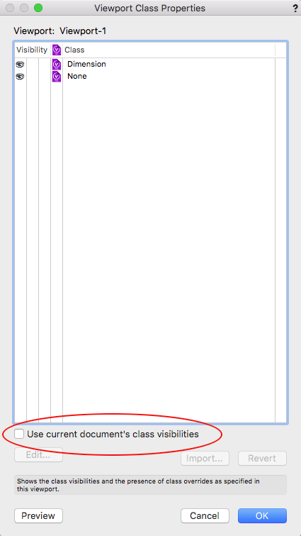
One other note: When you create your viewport, go find it on your standard design layer (whatever layer that might be), select it and in the object info palette, select CLASSES. At the bottom of the window there is a little check box with a tag that reads "use current document's class visibilities". You will ABSOLUTELY want to check that as it then allows your viewports to behave like every other piece of your drawing. Turn off the truss class and the VP truss turns off. Turn on the lights class and the VP lights will appear (or maybe the won't, but that is a "REFRESH INSTRUMENTS" issue that can happen to anything....I digress). When I first started using DLVPs I never noticed that one little check box and I was frustrated ALL the time. Once I figured that out, all was right with the world.

-
Each truss will need to be on an individual and specific design layer. Create a viewport of each layer and place that on your standard design layer. When you are done you should have five specific truss layers and five viewports on your standard drawing layer. Now go to to your standard drawing layer, select each view port, one at a time, rotate, and position regarding X, Y and Z values. That will create your model. For your plan view, there are two ways to do this: 1- layout all your truss objects in their respective design layers exactly as they would be installed on site. If you do that, you just need to add these specific layers to your sheet layer viewport. Simple as that. Quick tip if you are using this method; draw everything (or at least your trusses) on your standard layer exactly as installed first. Once completed, simply select each truss and move to it’s respective viewport via the object info palette. Easy. 2- draw the various trusses however you want on their design layers. Create a second plan view viewport of the structure and put that in your output sheet layer and then slide them about for your printing purposss. The first way is often the best, however, it is not unusual that you would have to do individual VP into your print outputs regardless because one production piece being above another, that sort of thing. Hope that helps.
-
The issue is that each truss has to be on a dedicated DLVP. Imagine the viewport as a picture (a very smart picture no doubt) of the contents of another layer. You cannot manipulate the objects in the viewport, you can only manipulate the viewport. I your case, you would need five DLVPs. This is exactly why I set my template file up the way I do. There is really no impact on my workflow. Draw the truss and lights on a dedicated layer, go to my main layer, turn on the necessary classes, rotate them and move them into position. Done. Probably quite a bit faster than trying to rotate a truss, and rotate fixtures to install on them and infinitely more flexible in terms of editing, exporting to paperwork and being able to manipulate the final object. There was a comment earlier about an issue with Lightwrite. I wonder why that would be? There is only one instance of any particular lighting fixture or any other symbol for that matter. I can’t imagine that LW can draw data from a viewport.
-
Sure Paul. I actually name the layers and associated classes by color. This may sound odd, however, when a shop preps a rig, they generally color code the trusses so why not start there. You can always change it later. So my DLVP layers are: red truss yellow truss orange truss etc. I then have DLVP classes that reside in my rigging master class with the same “red truss” naming convention. You could simply use DLVP 1 etc for both layers and classes. If I have an automated piece that needs to show a structure in multiple scenes, I just make duplicates of the associated classand send a duplicate of the VP there.
-
When you are layering objects, you generally have to include those physical layers, however, you can still cheat. For instance, you can pre-light a cyc or a pleated curtain object in another drawing, export the image and create a texture from that. I don’t find myself using cycs too often, but have certainly done that a lot with pleated drapes, stone, brick, stucco textures, that sort of thing. It can take a while to get the look you want, but once you do, rendering times drop dramatically and if you are like me, rendering quite often to see the outcome of new geometry, new set pieces, object placement, etc., you will find the increased speed of renders invaluable.
-
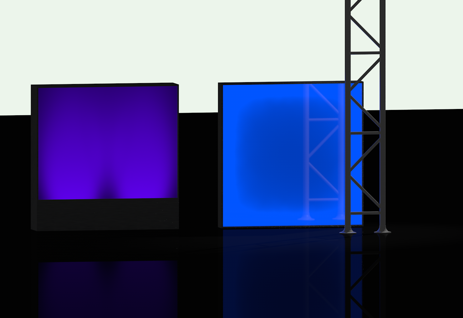
Here are a couple of examples of textures that "appear" to be backlit but instead are simply textures. The one on the right is a backlit piece of plastic where the back side is frosted and the front side has reflectivity. It would appear to be illuminated around the perimeter with something linear such as LED. The one on the right is a matte finish plastic with two lights uplighting it. This is also just a texture. The only light in this rendering is the one that is back lighting the truss so you can see the reflection. A few things to note: - Both textures were created in Vectorworks; the one on the left by simply focusing two spot light objects on a 4' x 4' white or possibly gray extrusion. I don't recall as it has been a long time since I've created these textures. The one on the right was also a 4' x 4; extrude and then I added a piece of geometry surround it to which I applied a glow texture that was emitting light. I adjusted the height of the extrude and the brightness of the texture until I got what i wanted. In both cases I just did a screen grab of the 4x4 to create the texture. While it may be easier to create these kinds of things in a program like Photoshop, we all have VW and you can, in fact, create these in VW so..... - Both textures are brought in as white and I select the "use object attributes" to assign colors. If you place all of your plastic on a class and assign the item;s fill to class color, then it is very quick to change colors globally in a project. - I have a ton of these textures in my texture library so I do not have to constantly create them. Hope this is helpful to someone.

-
You can do that by dragging the symbols into a blank file, making sure they are actually in the drawing and not just the resource browser. Then edit the class names. Note that every symbol you want to use would have to go through this process. The upside is that then they work as you are used to working. The downside is everyone else will be used to working with the original class settings so if you are sharing a drawing, an explanation is in order. I would like to know of there is any coding coding in the background that might be negatively impacted by changing class names. Any issue with Braceworks, worksheets, etc.?
-
I highly recommend NOT trying to light a surface like you would in the real world unless perhaps the only thing you are rendering is the set piece itself. Otherwise, this can prove to be a real resource hog in your renders. I’ve found it much better to simply create a texture that “looks” like it is supposed to and allow that to work for you. Your rendering times will increase dramatically, and making color changes is pretty instantaneous. You can create those textures in a drawing program like PhotoShop, Pixelmater, etc. or you can do them directly in VW.
-
SCParker, I believe the video in question was yours. Well done. It’s a shame that BraceWorks can’t calculate hinge blocks. That is a pretty common bit of functionality. I may just stay with my symbols until BraceWorks becomes a fully functional product. I certainly have found that my drawings slow down considerably using Spotlight truss symbols.
-
Thanks Brandon. It does seem like creating hinges as two symbols (like we have done for decades at this point) would be the solution, however, perhaps Bracworks can not calculate trusses assembled in that fashion. I’ve not looked beyond the 12” symbols. Are you saying that other sizes do ha e hinge symbols that are only one sided so you can put a pair together in any configuration?
-
After twenty some-odd years of using my own truss symbols, I am slowly starting to integrate the truss symbols from Spotlight. The reason is simply to have functionality for riggers using BraceWorks. Yesterday was my first run at things using some 12” truss. I needed an articulating hinge so I added that. From what I have been able to tell, there is no functionality to rotate a hinge. I found an online video that described how to create a duplicate symbol at a specific angle. (Very informative video but what?!?!) Is this how we deal with hinges now? I am assuming there is a much simpler method and I am just missing somethings. Any thoughts?
-
To clarify the “why” I do some of the things I am proposing: if if I have a piece of automation that is moving during an event, I need to be able to depict that in renderings to sell the idea to a client and in drawings to clarify what I need from my vendors. This is especially helpful to automation technicians as they will already know the cues we need prior to load-in. All of this is critically important to me and now instantly do-able by selecting which classes are on in a particular sheet layer viewport. With this scenario, any changes I make to the original structure (in simple to edit plan view by the way) will automatically track to every iteration of it in the drawing sets. 3D drawing will not accommodate any of this. As to scenery/sets, I am not necessarily thinking in terms of a theatrical set, which would be easily accomplished with layers and/or classes, but more in terms of scenic/set pieces that might travel about the stage in different locations at different times. You could, of course, turn the entire piece into a symbol and then insert that into various locations. That would work fine. Any changes you need to make to the piece could be accomplished by editing the symbol. The option that I often employ is to create that piece on it’s own layer and then create multiple DLVPs to move the piece around, including where it goes for storage when not in use. It’s just another way to handle those things that I find to be quite useful and why I suggest learning the use of DLVPs because it is far more than a simple work-around.
-
Agreed. That said, and I have said this before, DLVPs do offer quite a lot of flexibility beyond simply raking a truss. Let’s say you have some lighting pods that are automated at different trims and different angles throughout an event. No problem. Make duplicates of your initial DLVP, class each seaparately and move/rake to your heart’s content. Have a piece of moving scenery that travels about on stage? Same thing. DLVP’s are really quite versatile and those are just two examples of uses that could not be accomplished by simply rotating geometry. Clunky? Yeah probably, however, my solution to avoid the clunky aspect is to do the following in my template file: - I have ten design layers already set for creating DLVP’s. - I have ten classes already set up for DLVP’s. - I have already created the physical viewport for each design layer, assigned it to it’s appropriate class and turned on the “use current class visibilities” option. For me, all I do is start drawing in the pre-defined layer, go back to my standard drawing layer, turn on the appropriate DLVP class and rotate into position. Done!
-
To me, the big selling point of this process is not simply the ability to rake production structures, but that it allows you to print plan views without the raked truss. Avoiding wireframe 3D geometry in a 2D print is a huge deal to me. It also allows you to go back and add to or modify the structure very simply without changing working planes and whatever else.
-
Note: When creating your Design Layer Viewport (DLVP) insert whatever symbols and draw whatever geometry you might want on this new layer. Class it just like you would any other part of your drawing. Very important....add lighting element(s) on this layer as well. Without a lighting element, you will not be able to rotate the viewport on your standard drawing layer. Quick tip; once you’ve created the DLVP and placed it on it’s requisite layer, go to that layer, select the viewport, go to the OIP and select CLASSES. At the bottom left there is a check box that says something like “use current class visibilities”. Make sure to select that as then your viewport will act just like the rest of your drawing. Very important. I also seriously suggest adding a class specifically for assigning your DLVP so you can turn it on and off independently of your primary drawing.
-
Actually yes to both. I see a lot of guys that have files for specific types of similar items. You might have a file of “lighting instruments” or a file of “Martin fixtures”. In my case, I have one file with everything. I find that it makes managing updates much simpler since more than one person uses and adds to these symbols. When I open the file, the first thing I see is text that explains what updates have been made, when and by whom. In that file there are folders and sub-folders. In our master drawing template there are duplicates of all those folders (empty of course). When I import symbols from our library, they maintain their folder locations in the new drawing. If I have to grab a symbol from some other source or create one on the fly, then I still have the correct folders to use. I have recently become more focused on making sure any new symbol I create or snag from a third party gets placed where it belongs in my master symbol library. That way I can avoid the whole “now what project was it that I created __________ symbols?” nonsense.
-
If it is a dwg file or other file type, that is indeed a file > import scenario. If it’s a vwx symbol, it will come as an actual VectorWorks file. Then you can use the resource browser to import or drag the symbol into a drawing. I would edit the 2D/3D portions to your liking first however. Drawing and modeling of most simple objects is actually pretty quickly learned. It’s not as daunting a task as you may think.
-
If a manufacturer supplies a .vwx file for a symbol(s), you can import that directly into a drawing. Keep in mind that it might require some manipulation such as line weights fill colors and classing to work better in your drawing formats. Otherwise, you will need to spend a few minutes learning how to create hybrid symbols as you will probably have to import both 2D and 3D .dwg files. Again, adjusting pen widths, line and fill colors and classing to work into your particular style of drawing. While VW has become a more or less a “plug and play” drawing solution, there is no substitute for developing some decent drawing and modeling skills. If you do that, you can have any symbol you could ever want.
-
I have a 2014 MBP and a 2018. The 2018 is very noticeably faster; probably faster than my stupid expensive Mac trash can. What I have noticed is that the 2018 really throttles down when you put a heavy load on it. For instance, if I am rendering a single viewport on a sheet layer, it rocks along quite a bit faster then my 2014 and possibly faster than the tower. However, if I opt to render several viewports at the same time, it hardly works at all while the 2014 unit chugs through it eventually. I’ve not done any actual testing, but that was my observed perspective.
-
good point!
-
I believe that is part of the Braceworks functionality. Others will clarify.
-
I've not tried this, but Middle Atlantic might have a starting point for you. https://www.middleatlantic.com/resources/technical-drawings.aspx
-
Perhaps looking for symbols of connectors for rack panel drawings? If so, it’s pretty simple to find detailed drawings online and make them yourself. There may be a source for VW symbol library, but I’ve always just made my own.