scottmoore
-
Posts
673 -
Joined
-
Last visited
Content Type
Profiles
Forums
Events
Articles
Marionette
Store
Everything posted by scottmoore
-
Copy that. Ugh. All these tools that “sort of” work. It’s quite tedious and can certainly cause errors. Imagine the actual cost in labor and time if someone moved the origin, didn’t remember or even know they needed to refresh all the hoists, printed a coordinate sheet and hung an 80 point show completely wrong. Certainly within the realm of possibility.
-
Thanks guys. I’ll look at the first piece of advice from Andy and see if that sorts out labeling. I am pretty sure the second issue is indeed a bug. The XY fields did not calculate initially until I toggled the relative dimensions on and off. Likewise, when I moved the origin I had to toggle the relative dimensions back on and off to get the correct data.
-
I am trying out the Spotlight hoist tool for the first time and have some questions: 1.) Trying to use the Spotlight numbering tool. Selecting the “Hoist Number” field, setting the prefix to “L-“ and the start to “1”. When selecting hoists, the tool displays L-1, L-2, etc as one would expect. Once completed, all hoists still display “0” on both the hoist and OIP. The only way I can change the hoist number is to do it manually in the OIP. Also, it does not allow a prefix at all. 2.) I figured out how to remove the X,Y arrows so I am pretty thrilled about that. Now I am displaying the X, Y values from fields which I seriously prefer. The issue I now have is that the only way I can get the rigging point to display their actual XY location is to turn on “relative X,Y on plot” in the OIP and then turn it back off. otherwise I just get a value of 0. Any thoughts?
-
My apologies. I am returning the same results as you. Class overrides impact the lens, but not the light source. Adjusting the actual class attributes will change the light source, but not in a viewport override.
-
Attached is a test file. My assumption is you may still be relying on some bit of Spotlight functionality for lens and lamp coloration. This particular symbol is created from scratch and created on the specific classes that will line up with my design template. Basically, they are designed to be used specifically for rendering purposes. test.vwx
-
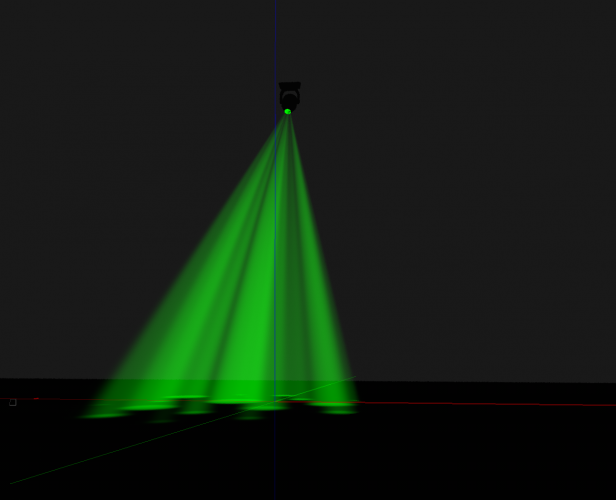
If I am following you correctly, yes I can adjust the color of the instrument lens and light in a viewport by class, independently of the actual class setting. I have duplicated two viewports on a sheet layer. In one, I have a set of wash fixtures I have manually set to yellow by editing the class of the viewport. In the other, I have set them to green. On the design layer, the class in question is still blue. So, I am assuming that is what you are hoping to achieve,
-
Actually no, I've not tried Class overrides. If I can keep VW from crashing every five minutes, I will give that a shot.
-
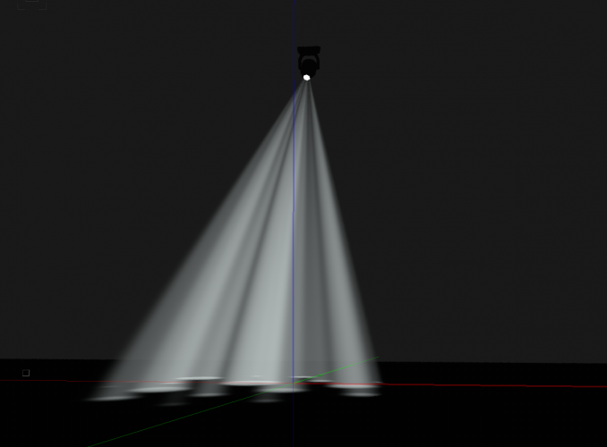
Here are some screen grabs. I avoid anything to do with Spotlight symbols so all of mine are custom geometry. Very simple to draw but how they are drawn and textured makes all the difference. In the instance of this gobo fixture, I create the body as a hollow object and a generic texture, not using a translucent texture. The lens is translucent and by building it this way, I can place the lighting object where I want to optimize the beam spread across the lens. Any additional spill is captured by the shell of the fixture body.
-
2020. Mine are purpose built symbols NOT Spotlight symbols.
-
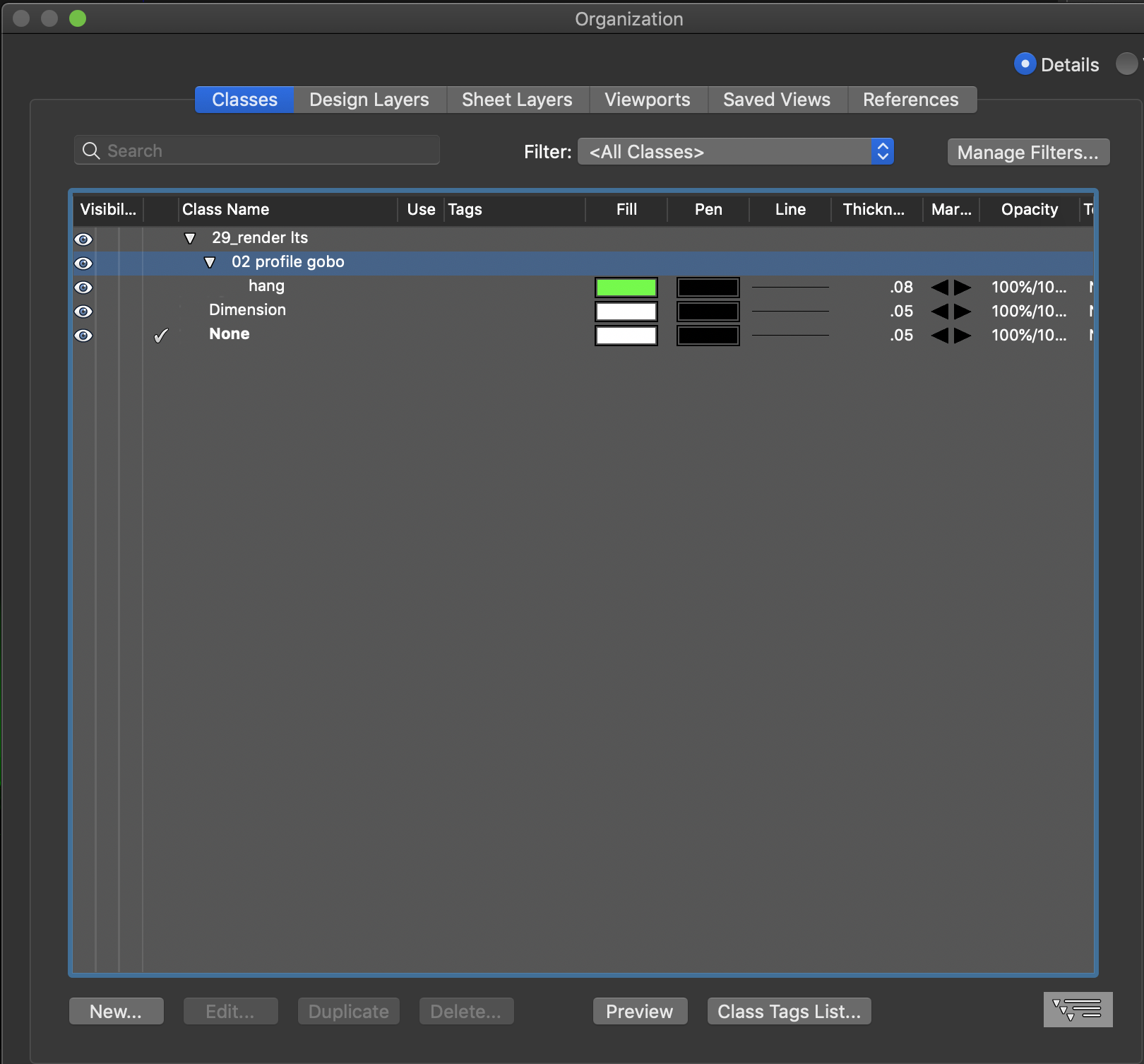
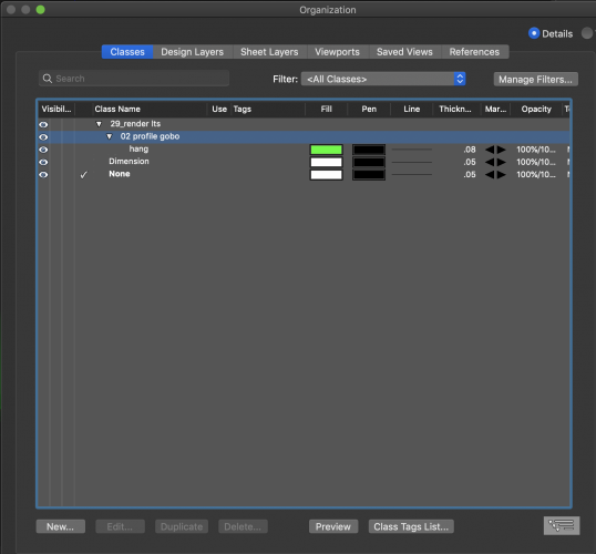
I build my own symbols for rendering purposes and create them in individual classes per type of light and it’s orientation (floor or suspended). The lenses and lighting objects all receive their color by being assigned to “color by class”. Works like a charm. The 2D element also changes fill color to make it easier to track changes.
-
I ran into a similar situation except directly on the design layer in 2020. If OpenGL is set to not display textures or colors, then Renderworks would not display them either. That does not make sense to me as I’ve always understood the OpenGL and Renderworks engine to be independent of one another but it was absolutely the case.
-
Make sure you are on at least SP2. Either SP1 or SP2 fixed most of these issues. I am still seeing the occasional oddity, but for the most part, this texture issue is resolved. I have noticed changes to reflectivity setting in textures. I have some lacquer finishes that had a reflection percentage of 25% that now need to be dialed back to 5%-10% to look correct. Not necessarily a bad thing as that gives us more latitude with reflection settings, but it is definitely different. Agreed with your beta tester comment!
-
This is all quite interesting to me. Seems like schematic view has a lot of potential. It is always disappointing when features are released before they are completely functional but that seems to be the case with many things. I don’t necessarily agree that drawing an item in 3D is “better” as that can often involve changing working planes but that may simply be a personal preference. After reading this I tested focus positions in DLVPs and sure enough, that no longer works. Rather disappointing.
-
An image prop is probably the quickest way to create a facsimile of an Edison lamp unless you need a close-up.
-
These tools are indispensable.
-
“Master Snap”? I learned something new! Thanks J!
-
The simplest solution here is to create a polygon and map your images to it. Ideally you would make sure all your content (textures) are the same size so when you map the initial image to your surface you can then simply replace the image. If you need to show various images in your renderings, then simply duplicate this surface multiple times and place each iteration on its own class. Then you can change images simply by toggling classes in various renders. Of course, you can also have the displays default to the class texture and swap images in the Nav palette. While having some additional functionality in the LED tool would be great, drawing polygons is pretty simple and easy enough to manipulate.
-

Curved Lighting Pipe with Roll Angle uglyness
scottmoore replied to Steve Boone's topic in Entertainment
I would assume that once you rotate the arc, VW is abandoning the 2D geometry in favor of 3D geometry by default. If that is the case, I would suggest creating a hybrid symbol. -
Perhaps it is just me, however, from a design mindset, it is important to get ideas out of one’s head and into the computer as quickly and accurately as possible. It seems like the initial design process has become overly complicated in service of simplifying the details required after a design has been approved. I find it frustrating and typically just avoid it altogether.
-
Curved Lighting Pipe with Roll Angle uglyness
scottmoore replied to Steve Boone's topic in Entertainment
Possibly check your VW system preferences? I am not at a computer currently but you can define the level of detail. Also, assuming you are using the sweep function, make sure you have your segment set low enough. -
It appears that the issue has been corrected in SP2 on both my desktop and laptop. I appreciate your hard work VW engineers!
-
The problem seems to have been rectified in SP2. Thank you VW engineers!
-
Indeed. That showed up when I upgraded to SP2 which means now I have additionally functionality that I do not want nor have any need for that will do nothing but slow down my drawings. Thanks for the info though Mark!
-
Updating to SP2 seemed to fix the issue. Now I have a loci in the middle of each symbol after I have used the numbering tool. Odd, but certainly not as big a deal as what I had earlier.
-
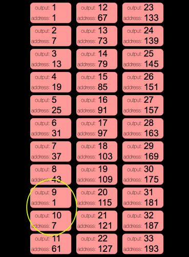
I've created a series of symbols used to identify cables for a specific use. Each cable has a label legend that identifies the DMX address and User #1 which, in this case, is the output to which the cable is patched. The color of the symbol denotes length. The information assigned to the cables is that they have a DMX footprint of "0" so that I can utilize the actual DMX footprint of the fixtures being used. For this instance, every cable has an offset of 6 for the DMX address and 1 for outputs so that cables should be output #1, DMX address 1, Output #2, DMX address 7, and so on. This all works great. I have the numbering set up to restart at 512 and that works as expected as well. The issue is that, for some reason, the auto numbering scheme cannot enter the numbers 49 or 55 in DMX address fields. See the attached image. As you can see, it picks right back up at 61 and then continues on as one would expect. When selecting those "fixtures" the data next to the cursor indicates 49 and 55, but that is not the data that is entered. Once entered, the OIP denotes 1 and 7 for those two symbols. If I start the numbering tool at 49, the first two symbols are numbers 1 and 7 and then it continues on to 61. The ONLY way I can get a 49 or a 55 is to directly enter the data in the OIP. As you can see, this is not a recurring issue every 48 channels as the subsequent symbols all behave as expected. I have run this with all iterations of this symbols package and have gone far enough up the address chain to get the units to reset after reaching 512 channels. I have also restarted VW. I am on VW2020 build 508509. Any ideas where to look for the issue?