
MaltbyDesign
-
Posts
257 -
Joined
-
Last visited
Content Type
Profiles
Forums
Events
Articles
Marionette
Store
Everything posted by MaltbyDesign
-
Moved question to Renderworks section. Moderators, please delete if necessary.
-
@Wes Gardner Thanks so much! It never occurred to me to use the drainage tool for this.
-
I found this post from early 2015 and was wondering if any solution has been found? Had hoped to be able to create a roof assembly using a slab and then rotate it to give it a 2% slope for a low slope roof. Since the create roof tool won't allow such a shallow roof, I was hoping I could do it with a slab, but apparently not. It may be that the only solution is to model the roof by its individual components.
-
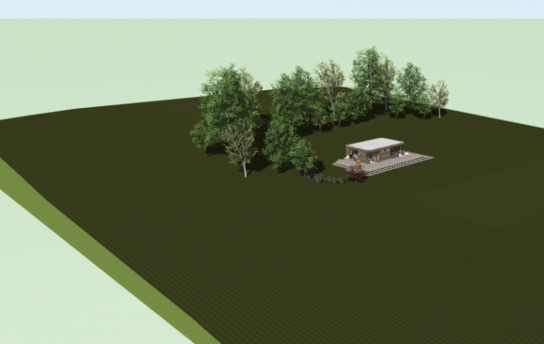
Hi Wes, Adjusting the 3D Fill didn't seem to work, nor did adjusting the 3D Triangles. I then decided to try deleting the dark grass texture from the resource manager for this model and the drawing updated to show the lighter grass texture. I got the result I was after but not sure how! Thanks for your help!
-
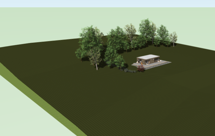
For some reason when I change the texture on my site model, the texture only changes on the 'skirt' and not on the surface of the ground itself. The attached screen shot shows the lighter grass on the skirt, which I can't seem to apply on the surface, which is stubbornly remaining the dark green gras texture. The texture is in my class "site-model" and I can't think of any other place to look to try and change the surface texture. What am I missing? Thanks in advance.
-

Doors with Sidelights Width Determination
MaltbyDesign replied to MaltbyDesign's topic in Architecture
@Wes Gardner Thanks very much! Is it possible to do something similar for transom lights as well? When matching windows with transoms and doors with transoms, using the same rise height doesn't present the same results. Once again it falls to trial and error to get them to match. When you sent the head height of the window and then add a transom, the head of the transom sits under that head height, rather than above it. Ideally, the window head would sit at the defined head height and the transom would extend above that, as they do for transoms applied over doors. -
Is there a way to draw doors with sidelights based upon an overall (say, rough opening) width? It would be nice to set an overall width and then the width of the door with the rest left for the sidelight. As it stands now, I can set my door width but setting the sidelight width appears to be based on the glazed portion of the delight. So, to get the whole thing to fit within an overall width, you need to go by trial and error or do a bunch of calculation based on jamb and stile widths, etc. This is a pain in the neck when you want to experiment with different stile widths. It would be nice to just set a door width and overall unit width. Is this possible? Thank kindly!
-
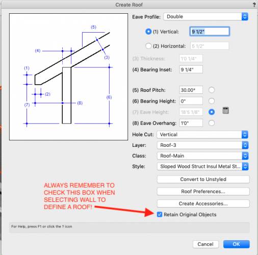
@Wes Gardner I was looking for turned off classes and all sorts of things before I clued in about checking that little box at the bottom.
-
@Wes Gardner I hope you can help me. I used the Two Storey Split Level Trainer that you posted above on Posted November 9, 2018 with, what I thought, was some success. I understand the process that you illustrated in the training but when I applied it to my own small project I've come up against a hurdle. I created walls, slabs, foundations, etc. per the trainer but as soon as used "Create Roof" the exterior walls below the roof disappeared. I used all the same settings as in your exercise so couldn't't figure out where I went wrong. So I thought I'd try an experiment and went into the Two Storey Split Level Trainer and deleted to roof in that drawing and as soon as I applied the "Create Roof" tool, the walls below the roof disappeared as soon as the roof object appeared. Is there a glitch or a setting that I'm not seeing? Any help would be appreciated. Edited to add, I thought of the answer while walking the dog. Embarrassed at how simple the solution is.
-
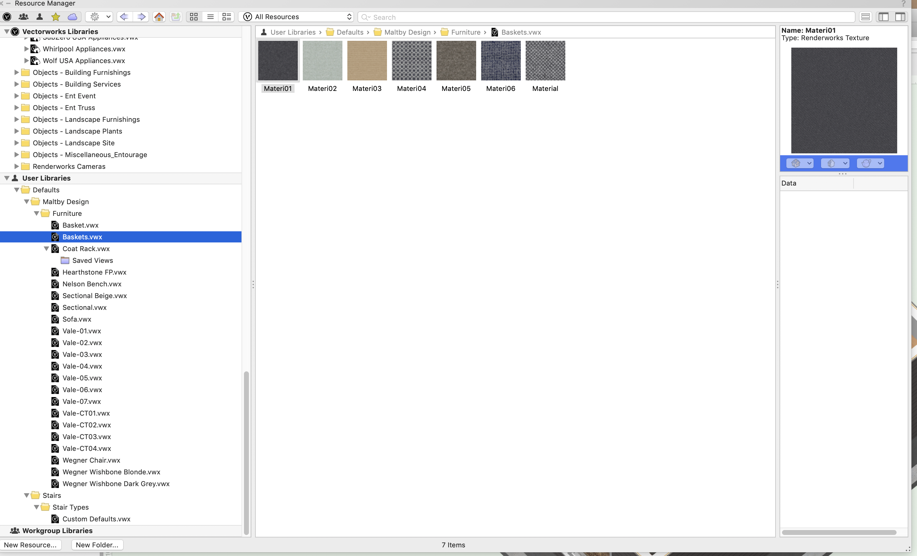
@Boh I worked through your instructions and managed to get things working properly. What I discovered was that I could rename one of the models "Furniture" and once in that VW file, convert the model into a symbol and define its view and render works style. This file showed up in my User Library in the RM. I then opened each individual model, converted it into a symbol and, once I set the view and rendering style, I could drag it into my "Furniture" VW drawing in my User Library where the new thumbnail became viewable. I did this for each of my furniture models and all worked as expected. Thanks again for taking the time to explain the process.
-
Thanks for the detailed reply, Boh. I'll work through it and see if I can get it figured out.
-
All of the files in my 'Furniture" folder are 3D objects that I had converted from SketchUp at some time. So if I open each file I'll see the model of the particular piece of furniture. So should I convert the models to symbols? Is there a way to get these to shop up in the manner that the regular objects appear in the RM? For example if I click on the Kitchen Appliances and Accessories in the Objects - Building Equip_Appliances folder in the Vectorworks Library, I see multiple symbols with the textures in a separate folder. If I convert my furniture models into symbols will I be able to do something similar?
-
Thanks, Boh. I found that and my files loaded on startup. However when I click on one of my objects in this file, all I see are the textures and not the model itself. So I have no way of bringing the model into my drawing like on the standard VW menus. I notice the standard VW menus have multiple objects in a sing VW file. Should I be doing this and if so, how do I do this?

-
Thanks Boh, but I don't see a user folder anywhere and am wondering where to locate it so that I can access it from the resource manager.
-
I'm a bit confused about where to create a User Library to store various 2D and #d objects/symbols that I've collected along the way. I want to have a folder that won't be overwritten each time I update to the latest version of VW. From what I've read it goes into the Libraries folder but all I see are the default object folders that I see in the Resource Manager. If a add a folder here, won't it disappear when I install VW 2020?
-
Finished Floor Slab and Structural Slab on separate Layers?
MaltbyDesign replied to MaltbyDesign's topic in Architecture
Hi Wes, thanks for that. I think it was in one of your videos or other tutorials on setting up stories where you recommended not including the finished floor in the floor slab, which makes perfect sense to me, as a separate finished floor slab or slabs allows for easily varying the materials. Say, tile in on room and hardwood in another. I was looking for a z-offset for the whole door, not realizing there was one in the Threshold dialogue. Thanks very much for the tip! Edited to add: I think this is a great idea for the interior doors and allows me to have the finished floors terminate against the thresholds on my exterior doors, as they also have a 1" thickness to them but still have widths and depths, etc. -
I'd like to create a separate slab for my floor finishes as they may change from room to room, while my structural slab (sub-floor and joists) will be uniform throughout the building. At present, the top of my structural slab is set to elevation 0' with all of my walls and doors bound to this. I created a 3/4" thick slab for my finished floor (hardwood) and presently have placed it on my First Floor Layout layer which is where all of my first floor objects are placed (walls, doors, windows, millwork, furniture, etc). The first problem I see is that the doors are bound to the structural slab and are, effectively buried in the finished floor slab. The only way I can see having the doors sit on the finished floor slab is to place the finished floor on a second slab layer with it top surface set at elevation 0' and then set the top of the structural slab below the thickness of the finished floor slab. In this case, -3/4". But if I do this, then I think the walls would be bound to the finished floor slab rather than the top of the structural slab. How do others handle this? Thanks in advance for your thoughts.
-
@bgoff That potentially creates a lot of headaches keeping track of storey and layer elevations, etc. If possible, I'd like to keep my first floor at 0'.
-
@bgoff I'll give it a try. Thanks for the info.
-
@bgoff Thanks! I'm muddling my way through learning to draw in 3D after years of drawing in 2D. I'll figure out where everything is eventually.
-
@bgoff I think that would result in the contour elevations notations to adjust to the new elevation, no?
-
@Boh Thank you for the description. I'll spend some time today and work through your instructions and see how it works.
-
@bgoff Thanks ver much. I wasn't aware of the difference between Image Props and VB Visuals. It sounds like I could find images of trees in plan and add them separately to my site model to be viewable when in plan and if I put them on a separate class I can turn them off in 3D views so that all I see are the Image Prop trees and their shadows.
-
Hello, I've been trying to use some Image Prop files of trees available through the Resource Manager Vectorworks Libraries and they appear fine i various views except Top View. In Top/Plan they appear and a grey cross. Is there any way to get them to appear in the rendered Top View? There are VBvisual Plants available in the Site Planning tool set (Vectorworks Architect) but none of the plants on offer really match what actually grows in my area. Thanks in advance for any suggestions.
-
Adding a Building to a Site Plan Questions
MaltbyDesign replied to MaltbyDesign's topic in Architecture
Thanks, Boh.