
MaltbyDesign
-
Posts
257 -
Joined
-
Last visited
Content Type
Profiles
Forums
Events
Articles
Marionette
Store
Everything posted by MaltbyDesign
-

Detail Viewport don't show information drawn in annotations
MaltbyDesign replied to MaltbyDesign's topic in Architecture
@Tom W. @line-weight I wasn't even aware that components could show up in the sections. Checked the boxes in the OIP and now my walls show the components. Thanks to you both. -
Detail Viewport don't show information drawn in annotations
MaltbyDesign replied to MaltbyDesign's topic in Architecture
@Tom W. this sort of goes back to my earlier discussion about how far to develop a model. I've created wall types that show all the components but those components don't show up when I create a section viewport. For a job of this size, I'm not sure it's worth building a model stick by stick. The framing tool would save some time but I'd still have to model siding, air voids, insulation, sheathing, drywall, etc, etc. I'd have to double my fees just to take care of draughting. -
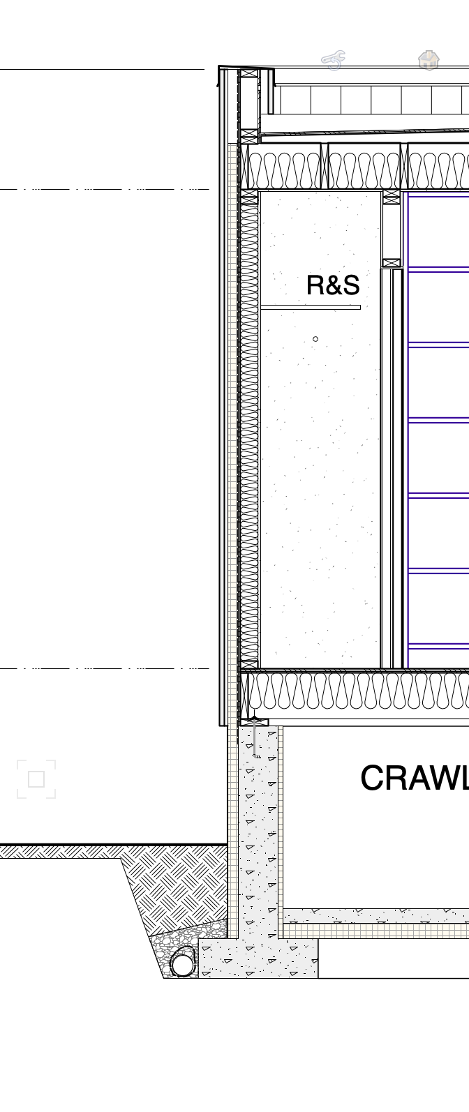
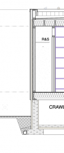
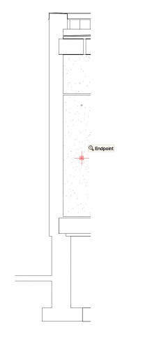
Hi All, I've created a couple of building sections, onto which I've added a lot of detail information such a framing insulation, etc. in the annotation viewport. When I create detail viewports from these sections none of the detail information I drew appears to have been carried over to the detail section viewport. I just see the empty wall, floor and roof outlines. Am I missing something or is it really necessary to draw all this information again on the detail viewports? For reference, the first image shows the section with the additional information added in annotations and the second image shows the bare section before any fill was added. This is also what the detail viewport shows.
-
@Wes Gardner That's what I was afraid of. It's a style of dimensioning that I've never cared for and would love for there to be an option to not include it that doesn't involve going into the annotation viewport and physically masking each incidence.
-
@Tom W. hmmm, I’m not at my computer so will have to explore it when I’m back in my studio.
-
@AlanW thanks. I’ll have a look and see if this will work.
-
@Boh I seem to recall doing it several years ago. I don't like the look of it and wish I could find an option to turn it off like you can for leaders.
-
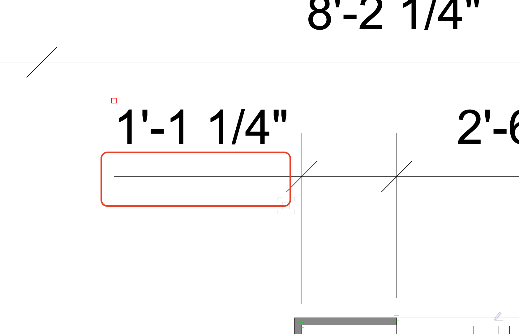
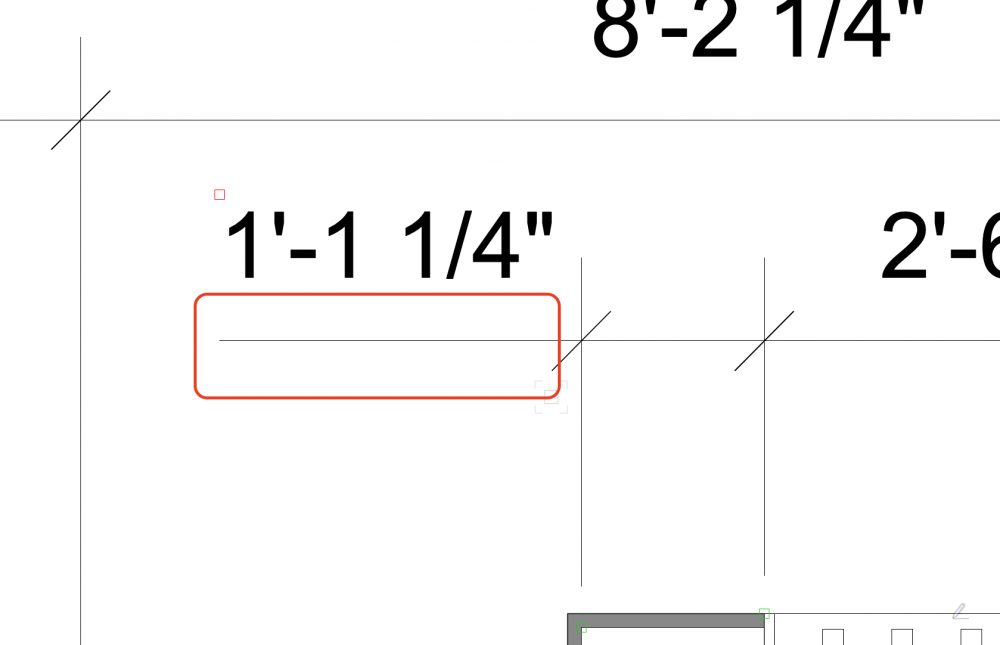
I know I've done this before but I can't see how it's done. When I move a dimension outside the dimension lines, VW automatically creates an extension to the dimension line which I don't want to see - see sketch with the line in question highlighted in red. How can I remove this from dimensions where I manually place the dim value?
-
@Tom W. Thanks very much. I've loaded that to my tool sets and will play around with it.
-
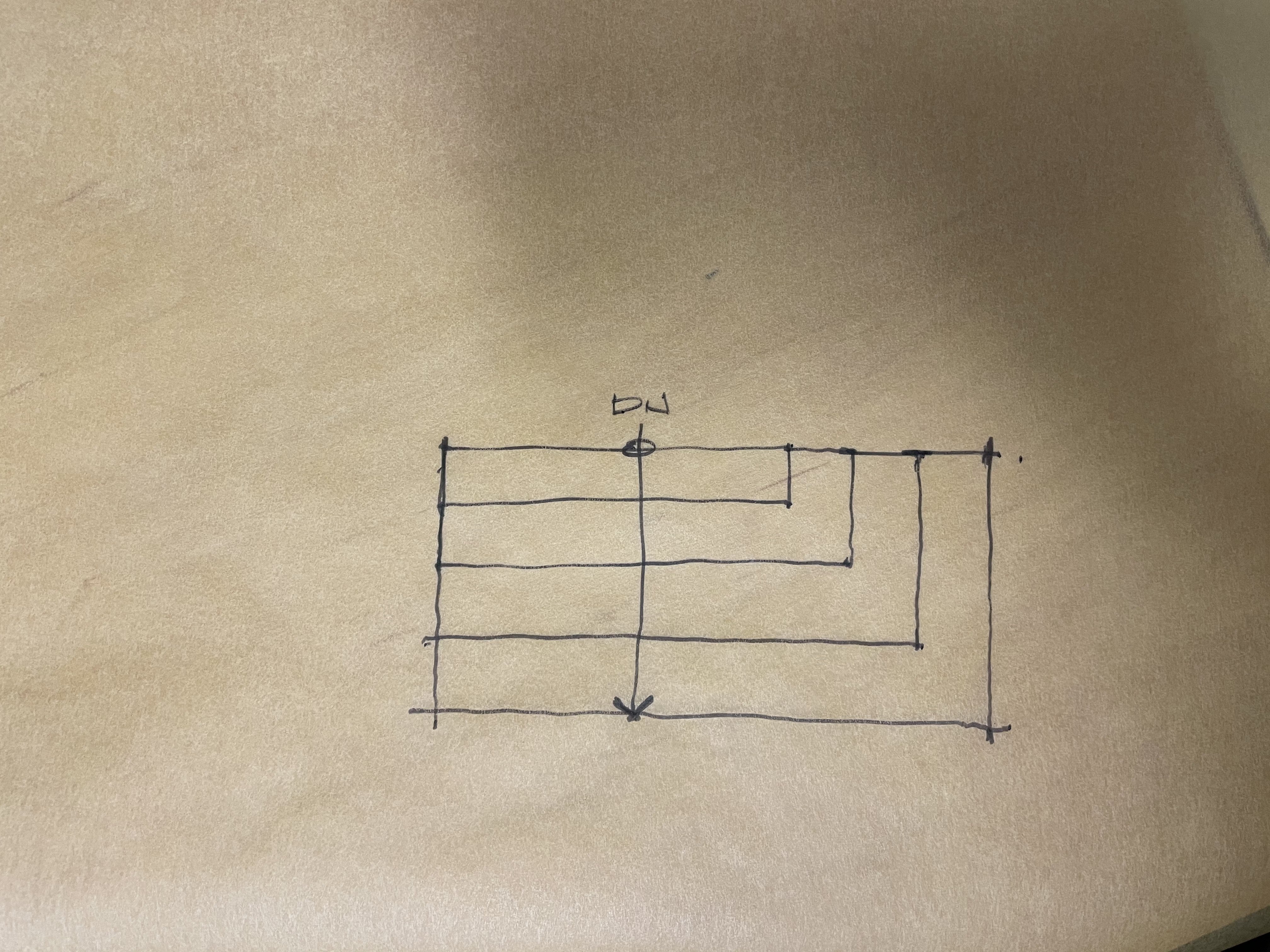
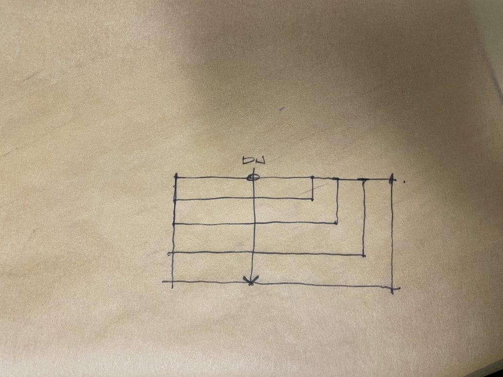
Using the stair tool, is there any way to have stair treads turn corners as they move down a flight like in the attached sketch? I don't see this as a possibility in the stair tool so am assuming I'd have to model the stairs myself if I want to do this.
-
@The Hamma Thank you for explaining the process. That worked.
-
@Dave Donley I work in the Architect Workspace and it doesn't show the option to Export to Unreal Datasmith. It does show up in the Architect-BIM and Fundamentals workspaces, though. How can I get this to show up in the Architect workspace? Or do I have to go into a different workspace when I want to export a file?
-
Ability to give 3d objects "2d" line types
MaltbyDesign replied to billtheia's question in Wishlist - Feature and Content Requests
Bumping this request again. Is anyone listening? -
@Tom W. you're much better at getting search results than I am. I try to search for these things and never seem to have any luck!
-
@Tom W. I was hoping there was a way of doing this that I was missing other than having to go in and "fudge" it in the annotations. I wonder if anyone who develops this software has actually had to produce a set of construction documents? Very frustrating to be always having to find workarounds for things that are, in my mind, fundamental to the task of drawing production.
-
Hello All, I have demolition items that I've assigned red dashed lines to in their classes. Walls, Floors, Roof Faces all show dashed lines in plan but when I view the model in elevation, they all show red solid lines. The Roof Face, in elevation, shows as a black solid line, not red per class. Is there anything I can do to show these items as dashed lines (per their classes) in elevation just as they appear in plan view? Thank you!
-
Metal Parapet Flashing (Extrude along path) Visibility Question
MaltbyDesign replied to MaltbyDesign's topic in Architecture
@Pat Stanford Thanks very much. -
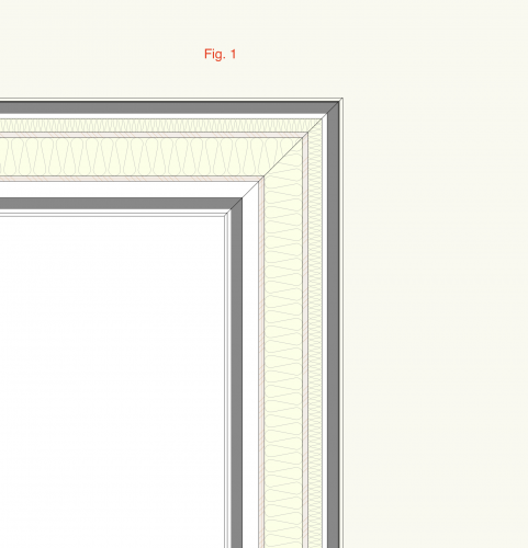
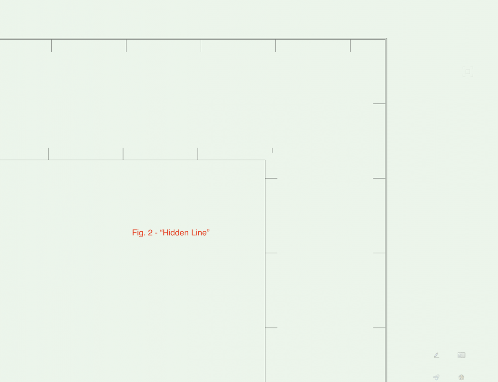
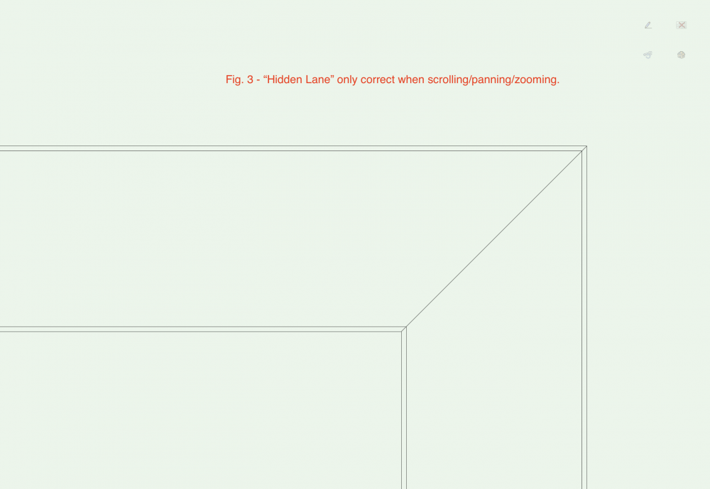
Hello all, I've created a parapet/cap flashing that shows up as planned in 3D views however in Top Plan it appears that I can't apply a solid fill colour so that it masks the visibility of the wall below. Is there a way to give "Extrude Along Path" shapes a coloured fill? The class texture works fine in Open GL and other rendering styles. See Fig. 1 I then thought, okay I can apply "Hidden Line" render to the plan, which does conceal the wall information below but it doesn't appear as it should in plan. I just get a set pf parallel lines with short perpendiculars. See Fig. 2 Fig. 3 shows what it should look like in plan, but it only appears this way briefly if I use my scroll wheel on the mouse to zoom in and out, or pan the screen. It then returns to how it looks in Fig. 2 Any thoughts on what might be causing this? Thanks in advance
-
@Dave Donley Thank you. That helps.
-
@Dave Donley Thanks for the explanation. Are there instructions available that explain this new process step by step?
-
@elepp This is, I think, what I was getting at (my term "real-time" may not be what I intended). When I watched the presentation for Enscape it looked to me like it was capable of live rendering directly on the model and you could make changes to the model and those would be reflected on the rendering. It seems Enscape is only available for Windows.
-
So how will this work? Will Twinmotion be bundled with Vectorworks like Renderworks is? Will it allow us to render our models in real time? As I understand it now, one needs to export a file to render it in Twinmotion. The problem that I see with that is that if the model changes, then you need to start from scratch and re-render the model to include changes. If rendering could happen in real time that wouldn't be an issue. I've never done rendering outside what's available within VW itself, so don't even know what I don't know. I've seen Twinmotion demonstrated and it looks pretty cool. Enscape also looks cool but isn't available for the Mac OS.
-
@Tom W. I hadn't thought of that. I don't see why not. Either way would work, I think, depending on whether one models using storeys or design layers.
-
@Tom W. I see what you're saying. What about having a different fixture and fitting layer for different floor finish thicknesses in a project? One for spaces with hardwood, with a 1" bottom offset; one for spaces with tile (bathroom and/or kitchen), with a 3/4" bottom offset; one for spaces with carpet, with a 3/8" bottom offset, etc. So each layer becomes a container for the various fixtures and fittings associated with a spaces floor finish. Is that too over the top? BTW, I'm okay with imperial. In Canada, I think the only people using metric are those doing work for the government.
-
By the way, thanks to everyone for contributing to this discussion. This is the sort of exchange of ideas I was hoping for.