Tom Lightbody
-
Posts
11 -
Joined
-
Last visited
Content Type
Profiles
Forums
Events
Articles
Marionette
Store
Everything posted by Tom Lightbody
-
Thanks Mark, that solved it. Still doesn't explain why it behaves differently in schematic views mind 😉
-
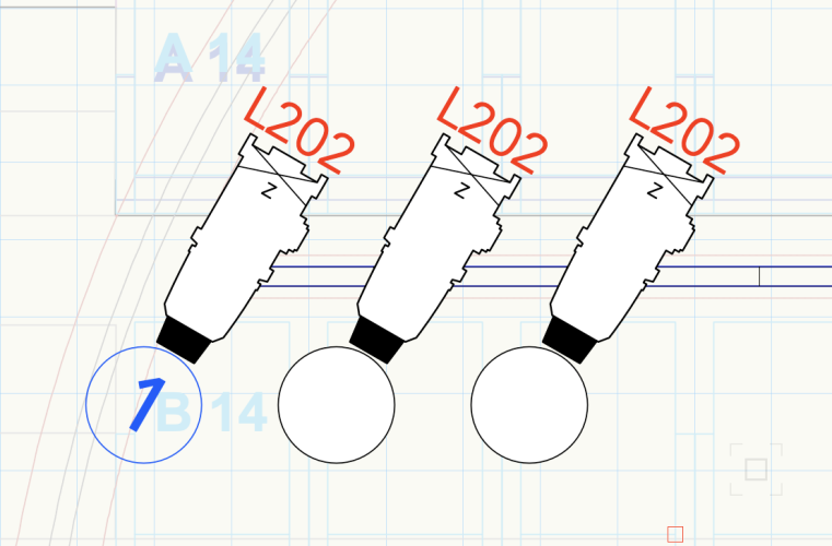
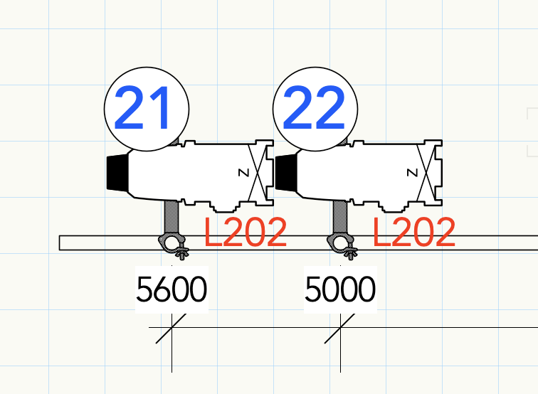
I'm trying to use Containers as part of my label legends but they're not doing what I'd expect. When I have no channel information on a unit, they seem to behave - ie I have a filled circle where the channel number would be (nb I've created the fill in the "Circle" container symbol). As soon as I add any channel info the container follows whatever the style is that I have set for the Channel label itself. In this example blue, with no fill. I've tried following Class Style, and manually setting all the style parameters, but it makes no difference. What's particularly strange is that in Schematic views it shows up exactly as I would expect - namely the text does whatever I've told it to do in terms of style, and the container displays exactly as it is in the Symbol.
-
I am forever battling to draw booms that work the way I feel like they should - which is quickly and simply. I want to be able to draw a simple vertical pipe which I can then use to rig units from using Doughty Boom Arms. In a perfect world I really just want to be able to keep a stock of symbols that I can deploy for booms of various heights. I've tried attaching the arms to the units as accessories, which is sort of fine once you figure out how to move them to be in the right place in relation to the unit in question This feels clunky but not impossible. BUT when you then come to make a schematic view, the boom arms are all visible alongside the unit, which just looks really messy. Is there a way of hiding the accessories on the schematic? I tried deleting the 2D element of the symbol but then they disappear in regular plan view as well which is not really what I want. The other option I've tried is positioning the boom arms onto a vertical pipe (which necessitates removing the various records from the default symbol in the VW library, which wants you to use it as an accessory...) before then making the whole thing into a single hanging position. Again this is fine, BUT when you come to make a schematic and want to do it in TOP view, it gives you a top down view of the whole thing (I think this is because it's a hanging position rather than a lighting pipe), rather than laying it out flat as it does if it's just a vertical pipe. I've got round this in the past by using a front view and creating 2D representations of the units for the "Front" view as well as the "Top" view, but frankly this is a pain as well. So what am I missing? What's the way to do this that doesn't involve extra manipulation? TIA, Tom
- 1 reply
-
- 1
-

-
Yes! I have exactly this problem. Doesn't seem to matter how I set the database criteria it doesn't seem to want to recognise attached accessories. -TL
-
Update: this appears only to be an issue when using symbols with Light Info Records attached. I’ve tried removing the Light Info Records from the symbol and it works exactly as expected. Anyone got any idea what’s causing this or how to get round the issue? Thanks!
-
No joy 🙁 The 2D elements are now all polygons, but the problem persists. I have both “Background Render” and “Foreground Render” set to “Hidden Line” in the OIP, and “Display 2D Components” selected.
-
Thanks guys. I have 2019, so hopefully that’s not an issue. The 2D component is made up of polylines though... I’ll try making a polygon instead when I’m back at my computer.
-
I'm struggling to get 2D renderings to appear when using viewports, and can't work out what I'm doing wrong. I've edited an existing hybrid symbol to include 2D representations for each of Back, Front, Left, Right but no matter what I do I only ever seem to see only the 3D object in the viewport. I honestly have no idea what I'm missing so any help would be appreciated. Thanks. I've followed the workflow here: http://app-help.vectorworks.net/2019/eng/VW2019_Guide/Symbols/Workflow_Using_2D_Components_of_Symbols_and_Plug-in_Objects_in.htm#XREF_17531_Using_2D
-
Amazing. Thanks so much. I'm sure I used to know how to do that but it's 10 years since I used VW.
-
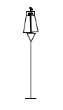
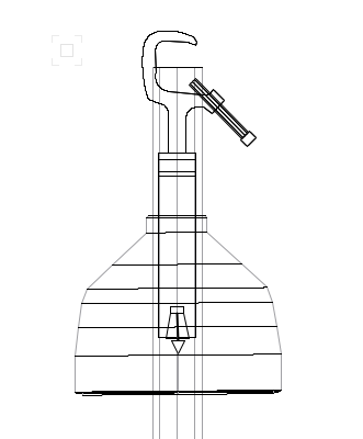
Hi all. I'm trying to set up some viewports to get everything I need on to one page from a larger lighting plan, but for some reason in any 3D views, all of the lanterns are showing with the light source (which doesn't scale - two pics attached; one zoomed in and one zoomed out) and I can't for the life of me get rid of it! The same issue is not present where viewports are not involved. Any help much appreciated.


-
I'm fairly new to architect (been using Spotlight for a while) so am working on a few projects to get me going. I've got the basic model of my house drawn up, and have constrained the walls to each other on the 1st, 2nd and 3rd floors, and have put in associative dimensions for all of them as well. My issue is that when I alter the associative dimensions, I either get an error message (not compatible with other constraints already in the drawing), or the program just crashes and quits. If anyone knows what I'm doing wrong, then help would be most appreciated. I seem to be coping with everything else just fine but this is killing me as I have to reload the program each time I try something new to resolve it! Cheers. -- VW 2010, Mac OS 10.6 Snow Leopard