


Josh NZ
-
Posts
406 -
Joined
-
Last visited
Content Type
Profiles
Forums
Events
Articles
Marionette
Store
Everything posted by Josh NZ
-
Can anybody advise how to set up the wall components so that they will not show when that class is turned off?
-
I don't know how may times I have changed the plane mode to screen only, but I'm still having to continuously go back and keep selecting screen only. There was a post last year sometime that there was an issue where editing the crop of a viewport would cause this to happen but surely that has been fixed by now. Is this a bug or am I using this wrong?
-
Any ideas why this is happening? I have a hatch (grey background) that can only be selected by click on the edge or very center. Was able to duplicate the hatch and change background from grey to yellow, this is now selectable. I can't seem to see any setting in the hatch that won;t allow selection by clicking on surface.
-
Thanks for the info, next time it occurs I will reply here if the restart works or not. If a restart does work is there any additional info I can provide that would assist?
-
Hi Jim, have experienced on several files and on three computers. I have just re-opend this morning and once updated they have come right again. Next time the issue occurs I will try a VW restart and see if this is enough to resolve again.
-
This vid might also show whats happening, bit of a wait in the middle while wireframe renders sorry.
-
Any ideas what would cause the below to happen.
-
Thanks for the info guys. For the project we are working on at the moment there are about 6 unit types (A-F). There are then about 20 Blocks, each block comprises different combinations of the units, eg ABABA, ACFCA, etc. Was thinking the best approach would be to have a separate file for each of the 6 units. Then have separate files for each of the 20 blocks. Each block file would have several referenced viewports that look at the respective unit files. From that point was hoping to use the sheet layers to set up the working drawings, eg ground floor plan has than layer on, roof has class override so dashed and no fill etc. If that is not possible I'm guessing you will need multiple design layer viewports, eg one DL ref VP with roof on solid no dash (for use on site plan), another with a class override so dashed and no fill (floor plans). Does that sound like the best way? Hope that makes sense.
-
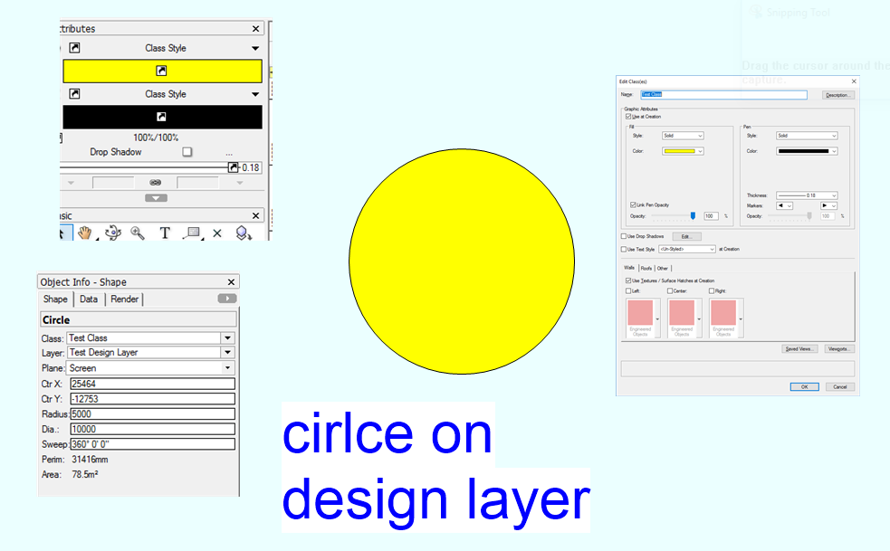
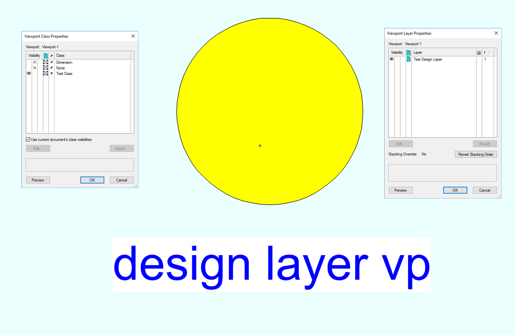
I'm having a bit of trouble with some referenced viewports not showing the class overrides as desired. I suspect its a combination I'm getting wrong with respect to "use embedded..." In the examples below, I have a circle assigned to a class with attributes set to class. In a separate file I have a design layer reference viewport which only looks at the layer and class of that circle. I then have a 3 sheet layer viewports, 2 of them have class overrides to adjust the fill. As you can see in the last image there is no change to the fill. The design layer viewport has "use current document's class visibilities" ticked, as not concerned about the settings in the referenced file. The sheet layer viewports have "use embedded design layer viewport settings for class overrides" unticked, as is the sheet layer class settings (overrides) I want to use. Hope all that makes sense. Thanks in advance to anyone that can shine some light.

-
 The fit walls to objects command can be a bit limited as you don't have any control as to which objects it is trimming to on the chosen layer. The main example being for renovations when there is say a section of roof being removed and therefore classed as such. Once the new roof is created and walls trimmed to the roof layer, the walls will still trim to the removed roof even if that class is off. The workaround is to either temporarily remove the roof , or put the removed parts of the roof on another layer which is against the "layers = where", "classes = what" method. Would be handy if there was a way to say trim to objects on layer, and maybe tick visible classes only.
 -
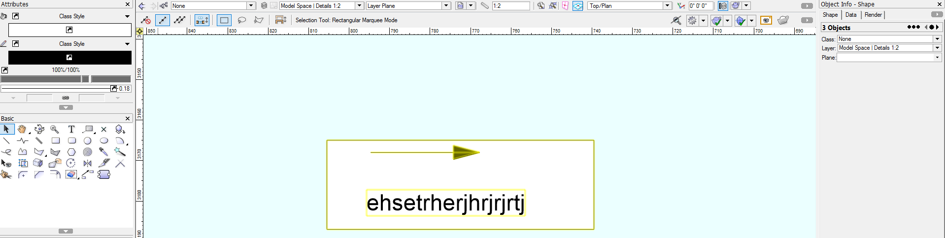
I'm having a bit of trouble getting the Text and leader line positions I am after. The text and arrows in blue in the below image are what I am trying to achieve, eg Text alignment left with arrows off the end. Have tried the 4 combinations of "Horizontal Position" and "Horizontal Text Alignment" as shown in red and not getting any success. Any ideas what I am missing.

-
3D Sectional Viewport (not perspective)
Josh NZ replied to Josh NZ's question in Wishlist - Feature and Content Requests
Altering the height range got it to work. The section line instance didn't appear to have any effect. -
Thanks for that Itchy, will give that a try.
-
3D Sectional Viewport (not perspective)
Josh NZ replied to Josh NZ's question in Wishlist - Feature and Content Requests
Ive had a little bit of a play around with the settings but not having too much luck. In the image below I have two VPs. The left one for some reason has the view set from quite far below the building. The one to the right is better but not 100% what im after. I can;t seem to find anywhere to alter these views. First check was to right click and hopefully edit camera but that option isnt there. There also doesnt seem to be anything in the OIP. Im sure its right in front of me but not having any luck.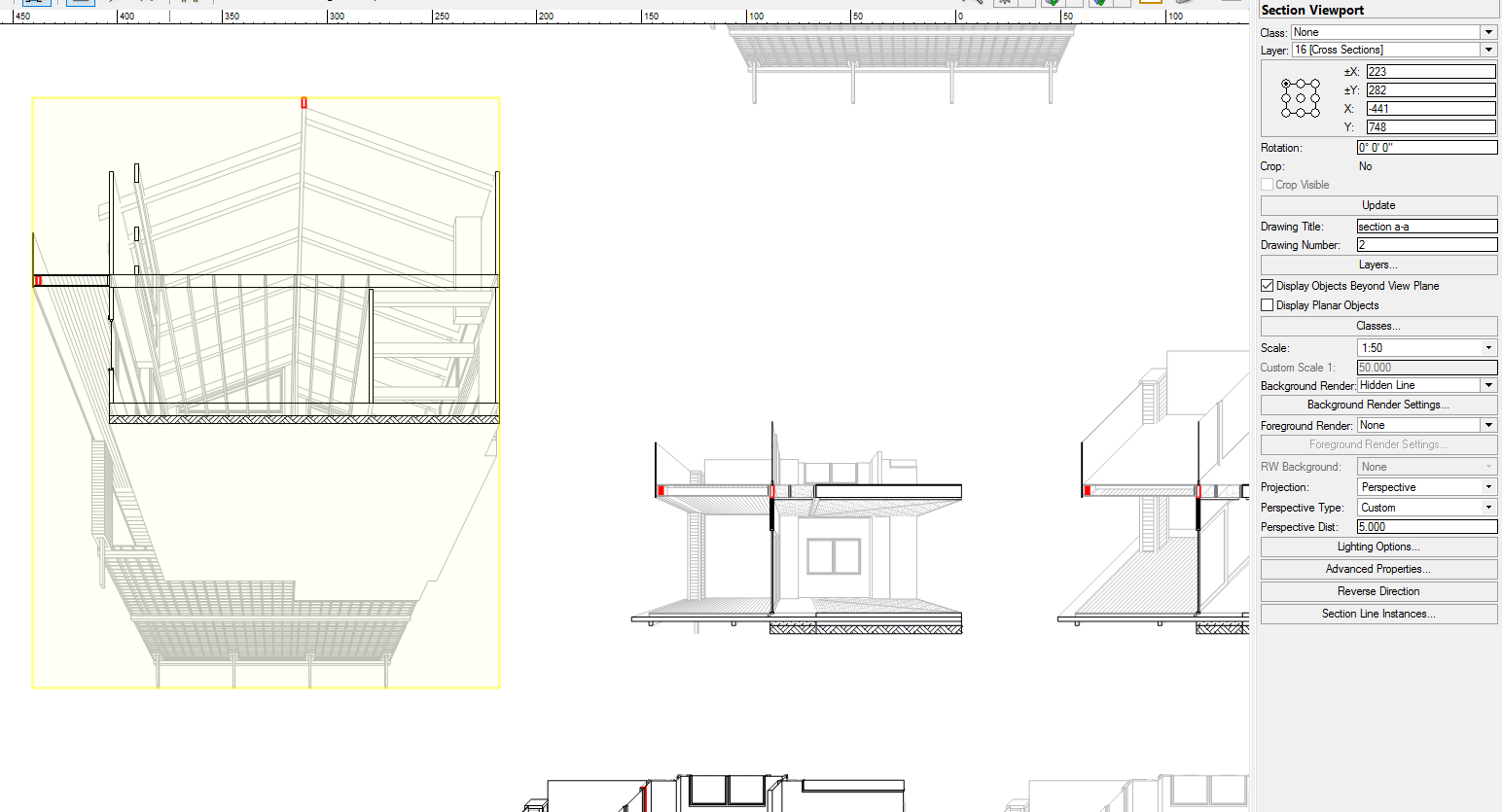
-
3D Sectional Viewport (not perspective)
Josh NZ posted a question in Wishlist - Feature and Content Requests
-
Thanks Alan, the option was there before but now not present. Will try a restart.
-
3D Sectional Viewport (not perspective)
Josh NZ posted a question in Wishlist - Feature and Content Requests
Is there a way to show a 3D sectional viewport similar to the image below? I have used the clip cube. If I create a viewport is say right isometric then the VP shows the entire structure, note the cropped view as in image. If I use the create sectional viewport then the view is either perspective or if using oblique cavalier then only one direction of view.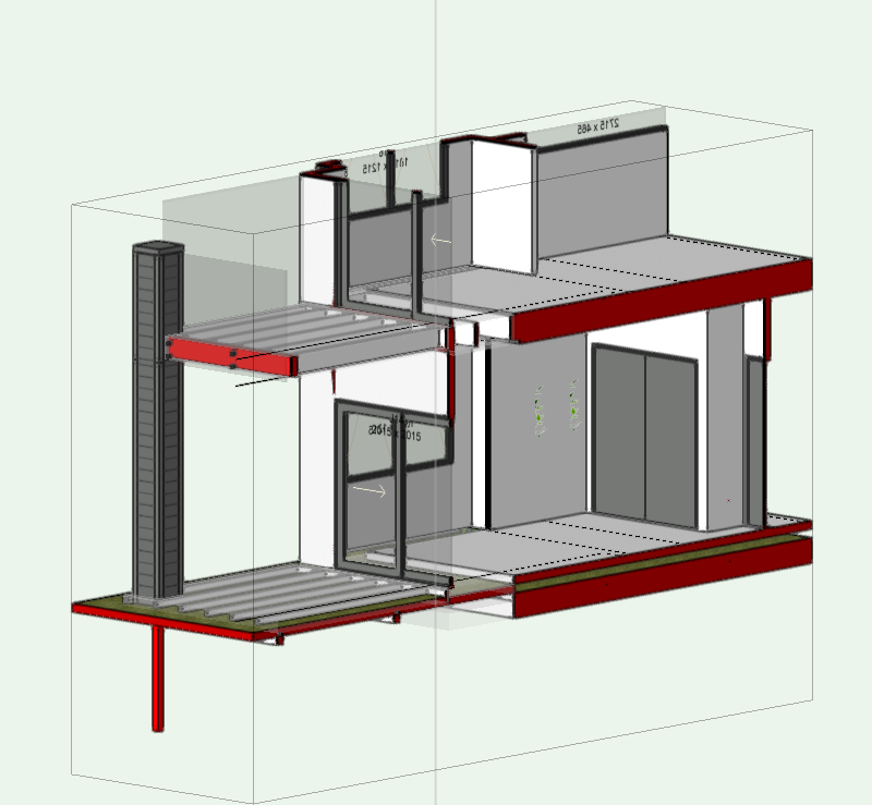
-
Also I seem to have lost the ability to add a shadow?
-
There is an option to add a box to the text of a dimension. I haven't seen the same option for text. Have looked in the OIP and Text menu command. At the moment we are having to draw a rectangle underneath the text and sometimes group. Is there an option to do add a border to text?
-
Many years ago a few of us in the office tried as well but never had any luck so gave up. The new version seems to be quite intuitive. As far as the physical VW camera object question goes, this is beyond my knowledge. I'd be keen to find out also.
-
Thank will try that. Yeah had the R2 on the edge of table but skewed incorrectly. Nudged it down a bit so more accurate.
-
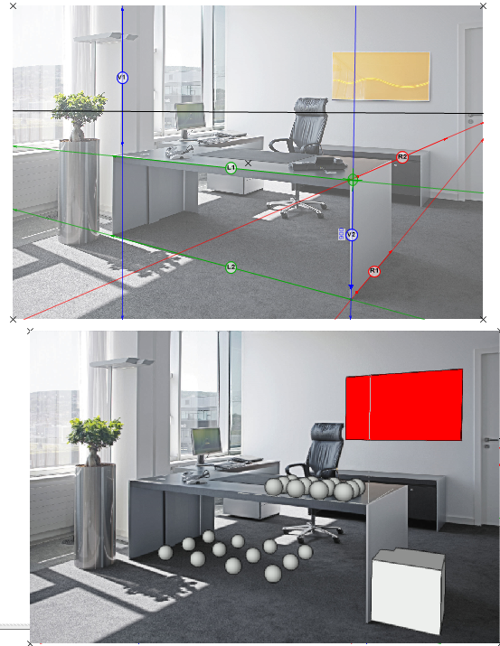
Have just watched the camera match tutorial, what an awesome tool, had never seen it before. My only query is that it shows fine in Open GL and hidden line, as soon as I change to final quality the objects disappear. In a couple of attempts with copying and pasting VP and changing the render type, I got it to show but then showed all the vanishing point lines. After ticking and unticking planar objects, the lines disappeared but so too did the objects.
-
I forgot to mention the most painful one for me. Adding Fields to the Space label. Almost all objects have an "add" component field tab. Examples being walls, roofs slabs all have add component tab. Hatches have add level. I think records etc have add field. With the space tool in order to add a field you have to edit the LAYOUT, copy the text which says #1#, rename it #2#, exit the settings... re enter now you can assign info to the 2nd line. If there is an efficient way to to the above pplleeeaaassseee let me know.
-
Great, thanks for the update Itchy.
