


SCParker
-
Posts
592 -
Joined
Content Type
Profiles
Forums
Events
Articles
Marionette
Store
Everything posted by SCParker
-
 Thanks. That worked.
 -
Greetings, I have dozens of lights that I've placed using various methods including Mirror, Duplicate, etc. These have duplicate Load ID numbers. Short of having to re-insert all these units, how do I renumber this field? Thanks, Scott

-
Vision 2017 - Service Pack 3 (SP3) Now Available
SCParker replied to PVA - Admin's topic in Vision and Previsualization
Does anyone have a copy of the demo file you could share? I can't find it. Thanks, Scott -
Getting the Mode to stick to a symbol?
SCParker replied to SCParker's topic in Vision and Previsualization
Thanks Edward. I was afraid of that. -
I have a unit (lots actually) that I want to always use in mode 1. How do I get the mode to stick to the symbol in the resource manager? Thus, having the mode already set each time I insert the symbol...
-
Rob, I re-imported the stock symbol from the VW library and it's fine. I tend to edit the symbols a bit and I likely did something strange to the record. Now that I've fixed the record issue, I'm re-editing the symbol imagery to match my liking. Thanks for checking in. Scott
-
Found it. Inconsistent parts records. Though most of the units are in the same family of brand, the parts records had different mixes of settings.
-
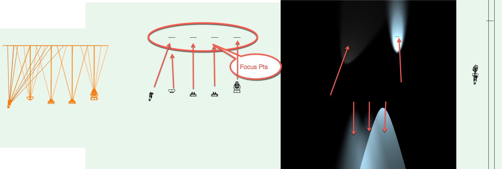
Has anyone seen this? If so, did you find a solution? I'm sure it's something I've done to muck something up. I have a set of four focus points above my lights. In wireframe, with beams turned on, the beams draw towards the focus point. But, when rendering, some point in the opposite direction.
-
Nicely done Dom. Thanks for putting this together. Scott
-
Check out "sketch" styles in the help file. Makes lines seem like they were sketched using an ink pen. You can also make changes to transparency to change the lines to seem like pencil. You have a bunch of settings to make the lines more or less rough/sketchy, etc. Hth, Scott
-
When drafting light plots I use viewports and design layers thusly: A viewport can reference external drawings. I reference my set designer's drawing via a viewport on a layer specifically named “REF-version 1“or 2, or 3, etc. this is particularly valuable when working in repertory as you can simply turn on and off the different drawings the set designer has created and have each one appear underneath your lighting equipment when needed. I have more than one layer for my light plots. One for overhead stuff, another for items that sit on the deck, etc. when I place my dimmer racks on the floor backstage, I place them on the "deck" layer. I need to know where the dimmers are in relation to the overhead stuff so I create a viewport cropped to just the layer area where the dimmer packs are. before doing it this way, I would simply have a duplicate of the dimmer pack on each layer. Since I've started using reports extensively, this gave me multiple counts of the same dimmer pack. Using the viewport method, my reports now show me accurate counts. As you know, layers and classes give us two methods of visibility control. Using an embedded viewport increases this to four methods. The layer and class of the of your current design layer plus all the layers and classes controlled by the viewport itself. It's a terrific rabbit hole to explore. Best, Scott
-
Save palette positions across multiple screens
SCParker replied to John Whyte's question in Wishlist - Feature and Content Requests
Do you do any work on just the laptop without the 2nd screen? I have the same thing happen when I've done work on a single screen and then open with the external screen attached. VW remembers the last screen used (most of the time) so using one screen resets the palette locations. Also, do you have your second screen set as primary, when connected, in your mac settings? -
Saved views are also particularly fantastic when working with others over the phone. Trying to get both people to have the same view is a challenge. Simply choosing "save view #7" and we both see the same thing.
-
I use the cable tools to figure voltage drops. I use Lightwright for power/phase info.
-
Editing 3D truss item, can't select the blue lined simplified box shape
SCParker replied to SCParker's question in Troubleshooting
Thanks Rob. Hmmm. I had all classes on, etc. I had to turn off and on the Simplified class to get it to show. It's working now. Go figure. Thanks, Scott -
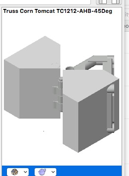
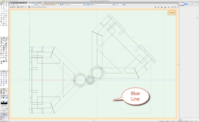
Greetings, I'm creating a few versions of the Tomcat TC1212-AHB symbol at different angles. I duplicated the symbol and edited to make a 45° version. There is a simplified shape that I cannot seem to select. In Edit 3D mode, the outline of the box is in blue. The second screen shot is what I have at the moment. How do I select the blue line shape to edit? Thanks, Scott
-
Not yet. It's in Sam's (the developer) wish list bin. He and I, among others, have chatted about it. I'm hoping he and John, from Lightwright, can figure out a way to link cable info, etc.
- 8 replies
-
- 1
-

-
- cable
- cable tool
- (and 1 more)
-
Instruments in 3D Facing Down (?)
SCParker replied to preston bircher designs's topic in Entertainment
Updated link location: http://www.vectorworks.net/training/2015/getting-started-guides/spotlight/Gsg-2015-s09-custom-lighting-instrument -
Thanks Edward. This is very helpful as I'm writing an article about theater dimming and how sinewaves are involved. Scott
-
Worksheet of Classes in a File
SCParker replied to Pat Stanford's topic in Resource Share - Vectorscript
Pat, This is a great help. One of the hard parts of the power of classes is remembering what we have. I don't know how many times I've created a new class for an object just to find later that I should have placed it in an existing class. Thanks, Scott -
Hello All, I'd like to be able to have a "cut list" be generated automatically from my extruded polygon items. I create construction drawings for stage scenery in 3D. A flat (fake wall used on stage) consists of 1'x3' lumber framed and covered with either cloth or plywood. Each 3D object has an X, Y and Extr value. How do I get VW to compile a list of all my (selected) items and these values? The attached file is a construction drawing I send to my scenery shop for building. Each piece of lumber has the sizes shown. But, it would be dandy to generate a spreadsheet list to place on the sheet. Furthermore, it would be helpful to compile a wood order for the lumber yard. These fake walls come in all sorts of shapes and sizes, so the wall tool doesn't really serve with ease. Thanks, Scott