RDS Casa
-
Posts
202 -
Joined
-
Last visited
Content Type
Profiles
Forums
Events
Articles
Marionette
Store
Everything posted by RDS Casa
-
Hello. Can anyone help on the velfac windows included in the library? I tried just dropping in the Velfac windows from the libraries. They don't look anything like the 200 (very popular) series. To me, they just look like some generic Lego style window which is named as velfac? I can't get the catalogue thing to work at all? any pointers? So I tried making my own simplified version. This has been better, but still frustrating. If you look at the attached file you will see two approaches. The one on the west wall is the best so far. (to understand the issue here, its important to understand the velfac geometry, where the opening sash sits in line with the internal timber frame. https://velfac.co.uk/domestic/technical/velfac-200/ ) See attached VW file. West wall. This was created using the settings and the offsets. Its a simplified version of the Velfac geometry. BUT for some reason it continues to want to sit the wrong way around in the wall. I don't know why this is. But if you try to add a cill, it wants to put it on the inside, so I know I have something wrong here. When I "reverse" in the settings, It seems to want to take a big chunk out the Jamb. Presumably because it thinks this is some kind of inward opening unit, so auto cuts back the jamb? So I'm currently having to use these the wrong way around with no cills. The one on the north wall is trying to use an architrave for the internal timber frame. This looks ok in plan, but only applies the architrave to the jamb and head, missing the cill member out. On the south wall is another version, based on the first. Here I tried to set it as a fixed casement (even though in reality it needs to be a side hung). The fixed casement options stops the configuration from automatically taking the chunk out the jamb. BUT I can't get this to sit the right way around in the wall? Any advice on where I'm going wrong, or better how the proper Velfac windows should work from the library? Thanks velfac window test.vwx
-
I was just looking for the simplest way to have repetitive elements in a wall build up. The complex line types combined with wall styles almost enable this in a really simple way. I've not played much with the framing tool to be honest, but yes, that looks potentially a better way of doing it (certainly for head plates and sole plates in the wall, and trimming out opening etc). But it's just another process and set up, that's all. At the moment I still take the sections vieworts when they are pretty much right, then when I'm ready I convert to group and edit the fiddly bits all in 2D. I know that's a archaic, and I'm left with a static section, but it works for me currently. Its the shortest way to useable output - until the design changes of course. Thanks for the suggestion - I'll look into the framing tool in more detail. If you know any good tutorials, do please post them.
-
Thanks But not in 2D? or will it? I found another work around for the complex line type approach. For one element, such as the insulation@90mm, I make 3 components. - one at 45mm with nothing in it - one at 0.01mm with the complex line type (which is 90mm geometry - I also put 44x90mm cls studs in it @ 450mm centres) - one at 45mm with nothing in it. This effectively put the insulation line and its complex geometry in the middle of where its supposed to be. So works sectioned either way. The result is ok. A stud wall in 2D. The stud positions are a bit random but no one cares about that. They put them where they want them anyway. The bad thing is that when using offsets and stories to bound them, you have to set up 3 components. and everything is 0.01mm out (but I'm ok with that now!) You also have to make line types for each stud thickness, but that's not so bad. This strategy also works for any repeat components. Like Stepoc Blocks in a wall. I had thought I could do beam and block floors this way, but then realised its only correct if sectioned them one way! I've put in a wish list for wall types to allow for a centre line (rather than just a left or right) in a component. This is useful for membranes also. I'd also like the hatch editor to be as simple as the complex line editor! which is not that complex Thanks for the suggestion.
-
I've been using complex line types to allow for repeating elements in wall styles. So for example I define a simple stud, with a repeat of 450mm as a line type. Then I use this in the left or right pen in the wall component. Works fine in plan. The stud spacing is off a bit at the termination, but no one cares. Also works well for putting insulation batts in a wall style. HOWEVER. this does not work when you use a section viewport... It works when sectioning the wall one way ONLY, but when it sections the other way, it renders the complex line geometry on the wrong side of the line. All this could be avoided by having a centre option AND this centre option would be better for placing dashed membrane line in the centre of a membrane zone, rather than bunching it up against the adjacent component. There are a few work arounds... one is to make a left/right and right left version of the wall style. The other is to create multi components which have no content to space things out. But neither are great. This might sort out these questions from 2012,
-
Ah... just discovered an issue with my approach. When sectioning walls, the left/right option for the complex line types does not work.... or at least it only works for any single direction of a wall. When sectioning the opposing direction, it renders the complex line geometry on the wrong side of the line. One work around is to duplicate the wall styles so there is a left/right style and a right left/style... but this is not great. frustrating, as if there was a centre line options, this issue would go away. Also could be used for a simple stud in wall approach.
-
Hello, Just searching for finding a better way to do this.... Maybe there is not one.... But its 2018 now. So I just make a complex line type (using world geometry scale) and make a repeating line type of the batt. Then when I make a wall style, I put this is on one side of the component edges and turn the other side of the component edge off. Works ok, not ideal rendering at junctions but no one seems to care on site. 2D only I guess. Please let me know if there is a better way. Thanks
-
Hello, Can anyone point me towards some videos/tutorials on making windows using windows styles etc. I have the basics, as per the std tutorials I can find. What I'm trying to do is to put a 2D symbol in at the jamb (only needs to be visible in 2D mode?), There does not seem to be any comprehensive videos about this, and about wrapping the wall components around at the wall termination. This one on doors is useful, because the same applies to windows. https://www.youtube.com/watch?v=vjb2sS1ESDY So this sorts the wall components.... And there are a few tantalizing options in the window style settings, but I can't get them to work as I need them. When I use the settings > general > use symbol geometry, it uses just inserts a symbol in the centre. Fine if all the windows are the same size. But they never are. I'm thinking there must be something that allows me to have one symbol on one side, and a mirror of it on the other, and stretches some lines between... I thought this might have something to do with the 3d hole in wall symbol type definition, but if it is, I can't get it to work. Is it because I'm not defining the symbol correctly? Can the parametric / associative geometry work in symbols? to lock end points of lines together and mirror etc? These can work making an object, but I don't know how to define it as a symbol that does what I need it to? (the more basic geometry from the std window tool is fine for the 3d, its just the 2d I want to enhance) The same question will come up for cill and head I guess. Thanks
-
Dear all. I have this. I guess its not fixed yet? Does any one know if there is a way to put a more detailed 2d symbol in at the jamb / head/ cill? (the system is fine for 3d, but not the required detail for 2d drawings) or is it a case of floating a more detailed symbol over the top where you need it? Slightly disappointed by the limits of this tool to be honest Thanks
-
Thanks. Scale using modify > scale factor?
-
Thanks cberg. 3d really. where are the image prop trees? in the subscriber libraries? I can find landmark trees, bring them in, but can't change their properties in any way.
-
Hello. Never really needed them before, but I have a question about trees in VW Architect (2018, VSS). Am I right to think I have very limited options with out generating the content myself? Either the VBvisual plant, with limited choice and no manipulation of spread, limited manipulation of height to set sizes only? Or the VW library content as a VSS user with no ability to change the std sizes at all? Is there a tool bar I need to turn on, or is this all a limitation of architect, with out the full landmark capability? Thanks
-
Also the terrain modifiers applying to proposed / existing option does not work. It applies the modifiers regardless if the modifiers are selected to apply only to existing or only to proposed, and the site model is set to the same option. The only way I can get optional modifiers to work is to put the modifiers in separate layers, then within the site model setting, ensure its only apply modifiers in selected layers and then select the right layers. VW Developers, can you look at this please?
-
No Answer posted for this? I have the same question. and another? how come when I take a snap shot it seems to offset the snap shot 5m ish in the z plane?
-
Thanks as always.
-
Hello all, I fear the answer to this is no.... But is there any way that a Boolean tick box input can launch/activate/or grey out additional input variables in the OIP? Like, include top member? tick, which un-greys a slider or user input box? or something Thanks Rob
-
Thanks everyone. I got the script working for what I need. I had not noticed the undo bug identified. I hope you swat it!
-
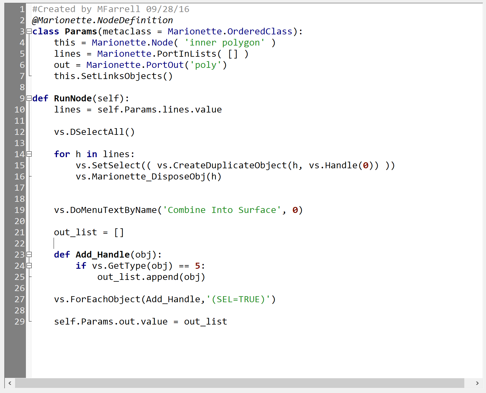
far too curious so tried it this morning. It works, thanks. So very helpful. I'm trying to improve my script further, so have tried to add a DoMenuTextByName command to put in "Combine in To Surface". I've ripped this from @Marissa Farrell compose node in another discussion. Which activates the tool, but also (because I grabbed it from a compose node) duplicates the objects and puts them in a group, which means I can't click inside the polygon. I tried taking out the bits I don't need, or at least I thought were bits I don't need, and the tool no longer activates. What am I missing? Thanks again.

-
awesome. I think this might work, I'll try it tonight. Thanks again, you have been a great help.
-
Hello, I need a script that take a lot of lines, and extends their length slightly. I'm not that far away I think. I hope there would be a set line length node... i.e just like if you select a single line, go to the OIP, put it on the polar display, keep the centre line fixed and put + 10 or whatever in the length. This keeps the centre in the same place, keeps the angle the same, but extends the length. So I can find a get line angel node, get line centre node, But the set line node is based on an start point and and point. I guess its possible to set the new points based on a trigonometric function from the centre point and the angle? but it must very close to 20 years since I did trigonometry!!! any simpler suggestions gratefully received. The reason I'm doing this is I need to tidy up a messy output drawing where hundreds of shapes are made up of lines and arcs BUT some of the lines don't quite touch (.0001mm) so I can't use compose. My plan is to make the arc sweeps longer (I've got this working thanks to some fantastic help from @Kevin McAllister on a different but similar problem) and make the lines 1% longer (keeping their centres and angles), and then create a closed polygon using the combine into surface paint bucket tool. The last stem is manual, but that's not the end of the world. If I'm missing any tricks, do please let me know. Thanks Rob
-
Answering my own questions again. I just found this Hopefully this will be useful to other searching in the forum. Thanks
-
ah, visible!!! I think it means visible! Perfect thanks
-
Hello, Easy one I think... I have a script that works, I need it to run on a range of selected objects. Whats my node? Thanks
-
Thanks so much. Can you explain the & (V) bit in the criteria?
-
mmm, bit trickier than I thought! This is the code in the "get layer visibility" node @Marionette.NodeDefinition class Params(metaclass = Marionette.OrderedClass): #APPEARANCE #Name this = Marionette.Node( "Get Layer Visibility" ) this.SetDescription( 'Returns the visibility of the referenced layer' ) #Input Ports obj = Marionette.PortIn( vs.Handle(0), 'hLayer' ) obj.SetDescription( "The input layer object" ) #OIP Controls #Output Ports visibility = Marionette.PortOut('iVisibility') visibility.SetDescription( "The visibility index value. Normal - 0, Inivisble - 1, Grayed - 2" ) #BEHAVIOR def RunNode(self): #inputs h = self.Params.obj.value #script vis = vs.GetLVis( h ) #outputs self.Params.visibility.value = vis This is the code for the "Objects by Crit" node @Marionette.NodeDefinition class Params(metaclass = Marionette.OrderedClass): #APPEARANCE #Name this = Marionette.Node( 'Objs by Crit' ) this.SetDescription( 'Returns a list of objects meeting the input criteria' ) #Input Ports #OIP Controls crit = Marionette.OIPControl( 'Criteria', Marionette.WidgetType.Text, '') crit.SetDescription('A text string defining the criteria, entered in the OIP') #Output Ports obj = Marionette.PortOut('h') obj.SetDescription('The list of objects in the document that match the criteria') #BEHAVIOR def RunNode(self): #inputs crit_ = self.Params.crit.value #script out_list = [] def Add_Handle(obj): out_list.append(obj) vs.ForEachObject(Add_Handle,crit_) wordTofind = "SEL=TRUE" searchInlist = crit_ searchInlist = searchInlist.replace(" ", "") if wordTofind.lower() in searchInlist.lower(): new_list = [] parents_list = [] for e in out_list: p = vs.GetParent(e) if vs.GetType(p) == 11 and p in out_list: parents_list.append(p) pass else: new_list.append(e) for g in parents_list: if g in new_list: new_list.remove(g) #outputs self.Params.obj.value = new_list else: #outputs self.Params.obj.value = out_list It feels like I should be able to adapt the latter to be, ONLY get objects specified in the OIP controls which are also on the layers which are visible in the organise dialogue??? How do I start? via multiple marionette nodes, or adapt the code in the crit node? Thanks
-
Very helpful, thank you. The drawings are cutting patterns which have come out another piece of software, and are going to a CNC workshop. They need circles because of the way their machine software distinguishes drill holes from pockets or routs. So the circle thing is technical, not aesthetic. One marionette problem I did have is "applying the script to selected objects" node???, which I know is simple but I can't find the solution. I've seen it done before but can't find the example. Hence I used the Object by Crit node to get the arcs as handles for the script. I'll try hacking the script in the node next, ideally I'd like it to apply to all visible Layers only, this way I can use it with the most flexibility. I should have thought of the purge command! simple Thanks so much