


Kevin C
-
Posts
158 -
Joined
-
Last visited
Content Type
Profiles
Forums
Events
Articles
Marionette
Store
Everything posted by Kevin C
-
Robert - I am sending you a typical file, which I have attached. It was upgraded directly into 2018 - I have only corrected the bugs that can be fixed (all as highlighted above) including word wrapping which for some reason has gone completely bonkers in 2018. This is highlighting quite a few features with the new title block - which could be really good, if they worked. Also, when I have created title sheets previously - I have always centred them on the page (0,0) Vectorworks has had a habit of changing the origin of a drawing whenever it suits itself (I think this only started to happen in 2017). When title blocks were attached to the border - this is not an issue, but it definitely is now. I am unable to use the title block until this 'bug' is fixed. The title block should work, wherever the title sheet is located. A perfect example is now having the revision No (or issue number) included as part of the overall drawing number, however the system as it currently stands does not allow an unrevised drawing to be issued - unless you want to have the word "none" appended to the end of the drawing number. Where there is no revision or issue - the title block should assume that the field is empty and not have a value included. Type_D_(House)_2018_(Test_file).vwx
-
The easiest way is to put an over-ride in the worksheet. In your door schedule worksheet switch on the database headers the select your door jamb column. It should be this one "=('Door'.'JambDepth')" then simply add on the thickness of the skim coat. Eg. if it a 3mm skim either side, you would add 6 and the field should then read "=('Door'.'JambDepth')+6". It will then add 6mm to each of the door jamb thicknesses, no matter the thickness of the wall - It will also just appear in the worksheet, as you are just over-riding the worksheet data and not the dataset. PS remember to switch off the database headers when you are finished. Kevin.
-
Additional window sash types required
Kevin C replied to Christiaan's question in Wishlist - Feature and Content Requests
Could I also ask for custom test markers to be made available for windows and doors. You could add to the 2D and 3D display options - "Custom text", or even better, add a line to the data tab that will display in 2D or 3D if filled in. An example would be "FEW" - Fire Exit Window, it is common for Building Control to require windows to be annotated with "FEW" on elevations and/or plans / also "FE" - Fire Exit for doors. The list could go on. -
Can I also ask that when reviewing any door and window tool that you take account of how doors and windows are placed within walls and that there is more than one way to generate a window / door reveal, which VW is very bad at doing. Also, if this is a Wishlist: When setting out a window or door it should be set out in relation to a specific component of the wall which we should be able to choose. My own preference would be to attach the window or door to the inside face of the outer leaf of the wall, so that whatever the internal wall make-up is, the door or window would be set out correctly and I wouldn't have to keep manually adjusting the offset to make it sit correctly. We should also be able to select a check reveal of a size which can be set in to the OIP You should assume in the first instance that when a multiple component wall is created or selected that the designer actually wants detail a project and the rendering is secondary (I think that you will find that is the case with the majority of users). If someone wants a beautifully rendered project, let them do it with a basic wall - but don't let difficulty in rendering prevent producing competent working details and drawings. Information for statutory consents and actual building is still done in wireframe drawings conveying the information to the contractor etc. There is no point producing beautifully rendered images and drawings if competent working drawings cannot be produced. IMHO, the only way to sort this is to think out of the box in relation to how we create models and present information. Allow the user to create a custom profile which can be simply attached to the door or window object and is in effect a 2D symbol with whatever customisation the user wants, creating in effect a hybrid door or window. This should also be able to be created in plan and section form so that we can add custom cills / lintels / thresholds etc. without having to navigate the current system that is not suitable for purpose. The holy grail and the best modelling solution is to be able to fully model each component and for VW will assemble correctly (or as instructed by the user), but as we have found time and time again, if the VW engineers are not given the correct detailed information at the time of creating a module, they will create to the best of their abilities at the time - or at worst, just make assumptions and once the module is created it will be working as 'designed' and very little can be done as it confirms to the parameters that were given at the time of production (no matter whether they were right or wrong). What is being proposed would create a simple functionality within the door and window objects that would allow users to attach the correct detailing parameters to each object. In relating this to BIM levels 0, 1, 2 & 3 - which is something that VW seems to champion at every opportunity BIM Level 0 - 2D Drafting with collaboration by paper or electronic means. The majority of the industry is well ahead of this. BIM Level 1 - Typically a mixture of 3D CAD for concept work, and 2D for drafting of statutory approval documentation and Production Information with an element of CDE, usually managed by the main contractor. The is probably the stage at which the majority of the industry is at just now. BIM Level 2 - This is distinguished by collaborative working – all parties use their own 3D CAD models, but not necessarily working on a single, shared model and all design information to be shared through a CDF - the only CDF for 3D models currently available is ifc or COBie. Note that detailing is not a requirement of BIM Level 2, although detailing must link to the building model - this can be done by simple referencing. The is where governments have said we should be at right now and where only very few VW users are, because of the apparent misunderstanding and difficulties that VW ( and all the other 'minor' design software providers) has because other suppliers are again championing their workflow and selling it as the only solution and from what I have seen, is no better than VW, but what they do, is listen to their users and admit when something doesn't work - throw it away and start again. They have is the ability to join up their components (roofs/walls & floors etc.). If VW is to try to remain a player in the BIM market, VW must look at its overall workflow and realise that there is no point having all this connectivity and fantastic modelling and rendering functionality if it struggles to get basic technical functions. BIM Level 3 - Currently seen as the holy grail, this represents full collaboration between all disciplines by means of using a single, shared project model which is held in a centralized repository. All parties can access and modify that same model, and the benefit is that it removes the final layer of risk for conflicting information. Again, detailing is not specifically mentioned, although it would not be too much to expect that each discipline would still be creating details (2D and 3D) within their own systems and have the project model make reference to them, as the ifc file format has a long way to go before it will be capable of supporting 3D models at that level of detail. It is also extremely unlikely that the 'Open BIM' model will be required to have the detail hard coded into it, but to have it referenced. VW has the capability to be a main player in this, but it must get its house in order. Things like automatic mapping to ifc are going to be critical / importing and exporting revit files - with full functionality (the import function loses all object data except the graphics) and the manufacturing and supply chain have already decided that rvt files are the file format of choice for objects (irrespective of BIMstore as the vwx and ifc object are almost non-existent). Taking this to the next level, detail hybrids could be attached to many of the standard junctions which VW struggles with and although the principles would be set out (as they currently are), when producing sections etc. the correct detail would always be displayed. The next stage would then to the details to be create the details as 2D/ 3D hybrids and attached as part of the overall structure. This could get round a lot of issues that users are currently wasting a lot of time trying to overcome.
- 25 replies
-
- 5
-

-
- window tool
- window reveals
- (and 3 more)
-
Better functionality of the Revision Box
Kevin C posted a question in Wishlist - Feature and Content Requests
Can we please have the facility to access the current drawing revision and display it in a title box at the same time as the Revision Block please. What I mean is that when using the Revision Block (and the Issue Manager), you fill in the current revision etc. that is displayed, but you have to manually include a revision edit to the title box. This should be automatic, but for some reason if you use the ":rNo" tag in your custom title box, it can only appear once - In the revision block, but not in the title block as well??? Also can we have some control over the format of the revision box. Ability to change the Headers from Date / Approval / Zone to something of our choosing - Like E.g. Date / By / Approved / Checked / etc. and choose whether to display or not -
This would be a great idea. The problem occurs whenever anyone mentions that they have a 'workaround'. This just means a bodge, not fixed or working properly, just a bodge. I am getting tired of 'workarounds'. Can VW please try and produce tools that represent actual construction methods and not representations.
-
Staircase object
Kevin C replied to Piyush Sanghadia's question in Wishlist - Feature and Content Requests
+++++++ Please please -
Housing layout plot numbering.
Kevin C replied to Dexie's question in Wishlist - Feature and Content Requests
Depends how your drawing is setup. I insert all of the house blocks as symbols into the layout The plot number (along with floor Area / bedrooms / In-curtilage parking / Handing / External finishes / Garden areas etc.) is contained in the attributes and displayed as part of the symbol on the layout. I use that to generate the accommodation schedules. I have a "Plot Report" worksheet in my resource manager which creates a simple spreadsheet that chronically orders the plot numbers. Any plots which get added or removed away, show up very quickly in the spreadsheet and the plot numbers can then be updated on the spreadsheet and they are updated in the layout. The 'plot report' is used really as a checking tool as for my last layout (426 units) would have stretched across about 2 A0 sheets vertically!! - VW still cannot 'word wrap' spreadsheet. Shame on you. -
Doors (and windows) are parametricly incorrect
Kevin C replied to P Retondo's question in Wishlist - Feature and Content Requests
Could I ask that if looking at the windows and doors then can you reassess they way that doors and windows are inserted into walls and how they interact with openings as they are sadly very poor. Solid wall construction went out with the arc - why do VW still assume we build solid walls. Allow us to determine the insertion mode and insertion position of a door / window. What I mean is allow us graphically to chose where the door frame snaps to: The outside face of the frame snaps to the inner face of the outer leaf and is inserted using the outer edge (frame) as the insertion point etc. (My preferred option) But to do this in VW you currently have to place the object then move to suit - very time consuming. Also when inserting the object, VW takes the entire wall thickness only - doesn't matter how many components make up the wall but to have an object positioned properly in a wall, it has to be inserted then manually adjusted by using the 'offset in wall' tool, which is fine, but beware if you change anything later as your offsets will all be wrong and have to be updated. Fix the internal and external wall detail components - work OK in 2D - but in 3D they do not (never have done) Sidelights in windows - Does not work whatsoever when you have any wall detail components selected Thresholds - Does not work whatsoever when you have any wall detail components selected Window cills - Do not work at all (Never have done). Again VW seems to assume that wall constructions are solid. THEY ARE NOT. Lintels - I mean structural lintels (what holds up the inner and external leaf of a wall) Openings adjoining multiple wall types - It is not uncommon (actually quite often) for a door or window jamb to be placed at a split in a wall construction, or a change in construction. The jamb tool does not allow for different LH and RH jambs and head detail - It is (wrongly) assumed that the same detail exists of all sides of the opening. This is just not true Could go on, but then you would just loose interest. -
Realistic Road/Grading Tools ??
Kevin C replied to nca777's question in Wishlist - Feature and Content Requests
Would ask that any improvements to the roads tolls be made available to Architect and Landmark. Have mentioned in previous posts that the ability to define filled polylines as roads would allow complex road geometries to be formed - similar to the 'create a slab' from 'create objects from shapes' but please remove the need to have pavements etc. just allow us to create the road with narrowing / widening, spaces for parking cars etc.. If we want to add a pavement or footpath - we could create it as a separate road object. Please please for the next release as none of the roads tools are of any use for creating anything but the most basic of shapes. -
It is really unfortunate that the road tools have never really worked properly. I tend to agree with Art V that not many people use the roads tools, as to be quite honest they are pretty useless, unless you have road pattern which contains no features and all junctions are a right angles to each other. I am also perplexed as to why the 'better' roads tools seem to be intended for VW Landscape (although I don't think that they are that much better). Can someone tell me if I my understanding of the design process has been wrong for the past 30 years. Example: Piece of land for sale - Client is residential developer. Say the site capacity is approx. 75 houses on a greenfield or brown filed site. Architectural, Engineering and client collaborate to determine best access to site, site constraints, existing wayleaves, SUDs location etc. Initial viability layout prepared - Architectural ONLY. (Either old fashioned set tip pen and tracing paper or VW - whichever feels best for site) Client signs off sketch proposals Bid Layout prepared - Architectural with engineering input (only if required for bid) Bid layout costed by client then submitted. Assuming bid is successful. the next stages are normally as follows: Detailed site design - Architectural and engineering ONLY Landscape Architect appointed - (but only if client deems it necessary for the development). It is not uncommon for landscaping to be conditional on a planning consent Planning consent applied for Planning Granted Building Warrant applied for Building Warrant granted Commence site works I have read on some replies to posts from people that they don't understand why people are constantly complaining. I have invested over £16,000 in vectorworks over the past 8 years. I cannot afford to go elsewhere. This is one of the biggest frustrations that I have with VW. There are now far better tools out there, but for me to change all of the licenses over would put me out of business so I am stuck. To make the system work all that really is required is the ability to convert a filled polygon to a road - without pavements, then attach pavements or service verges (or a combination) to the road. There will be people out there saying that what about road centrelines and stations etc. Simple, make defining a centreline (a simple polyline) part of the conversion to a road basis and that could then be used for generating stations etc.. Also if we controlled the location of the centreline, we (the engineer in this case) could properly model the cambers, gulley locations etc.so that a fully integrated DTM could be produced. It would also mean that the cut and fill could be more accurate - give the road the thickness of the make-up and any capping and it would then be included in the calculations. Sorry for the rant. I had roads sussed last month for a 35 unit site and the client loved it (unfortunately we didn't win). Went to do it again for another site and it just doesn't work as this site demands a more novel approach incorporating Designing Streets which means Have to just draw lines and arcs to form the roads. Kevin.
-
DWG import overwriting class definitions
Kevin C replied to Peter King's question in Troubleshooting
Peter, Just came across your post. There is a very simple way of importing dwg files without corrupting your VW datasets. First - Save your work and close the VW file (just in case the AutoCAD file is c**p and crashes VW) then do the following: Open a new black VW file (No template) Import the dwg file - You may have to try a couple of times to get the scales, geo-referencing etc. correct Go into the Organisation palette and change the fill and pen settings to what you want them to look like - As a rule I always switch the fill off and make everything a single colour (usually black). Change all the objects attributes to "by Class" - My preference as there is nothing worse than working in a file that has multiple objects with different settings in the same class. Save the file There are two options to import the data. Option 1 Open your VW file Create a new layer and make it active Go back to the file you created for importing the dwg file - copy everything (cmd+c) Tab back to the VW file and "Paste in Place" Option 2 Open your VW file Create a new layer by using the "import Design layers" function and choose the new file you have just created. Select the layer in the file (it will be the dwg file name - unless you changed it) Make sure "import layer objects" is selected Click OK Doing it these ways, you will be given the option of accepting or over-riding you VW settings for everything that you are importing and over-rides the undo lock that happens when you import a dwg file -
Snapping to geometry in referenced layers in rotated plan view not working VW2017
Kevin C replied to JJe's question in Troubleshooting
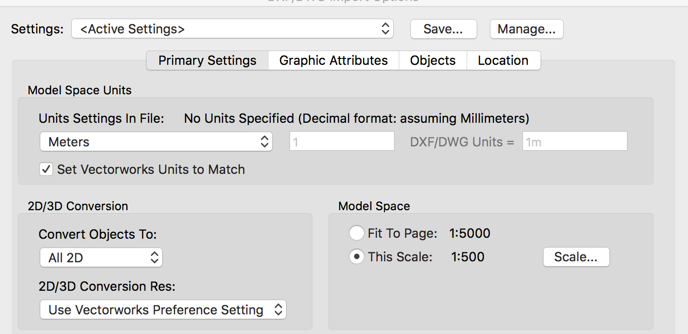
Just installed SP1 hoping that this problem was fixed - NO it hasn't. This is a serious issue. This problem did not exist is 2011,2012,2013,2014,2015,2016 - There has been a change to the graphics system. This is not as simple as a bug - there is a fault in the software. Oh and BTW - the "Update catalogue" problem is still there to. Jim, It has been assumed that we are working far from the origin - This is not the case, your response is based on the drawings being set up incorrectly. The drawings are set up correctly, the site plans (in my case) are either directly imported survey files or directly imported ordinance survey files. The procedure which is carried out each time is as follows: Create a new drawing (without template) Import topo survey or OS Map (settings as per Screen Grabs) - The topo would be imported in 3D if it is 3D, but VW seems to prefer importing as full 2D files (quite often the surveyor thought a few 3D blocks into the drawing, this just makes everything 2D). Go into the class settings and turn off the solid fill on every class (why are classes filled by default??) and then change pen settings to what I want Save file as a VW file That then becomes the base file for the site Create my layers for masterplanning and start drawing It is important to remember that the coordinates must match the GPS or OS coordinates in the survey files for the northings and eastings or I cannot generate coordinates or align the drawing with third party data (such as google maps) One of the great things about VW is to be able to rotate the view and work orthogonally, (so I am not having to twist my neck every time I look at the screen) and always be in a position to return it to normal with a simple click of a button - This is something that Autodesk does not have to the same extent. When I am working in a 2D environment and the site layout does not require the use of full 3D modelled files, I just use a symbol on the drawing to represent the house - this works fine, but when trying to work with a referenced viewport. Ie. referencing multiple model files to create a full model for client presentation / planning etc. I am unable to snap to points in the referenced viewport when the viewport is rotated. Please do not tell me that I am no longer able to work in a GPS coordinated environment. This is just the problem in this specific instance, it is endemic in 2017.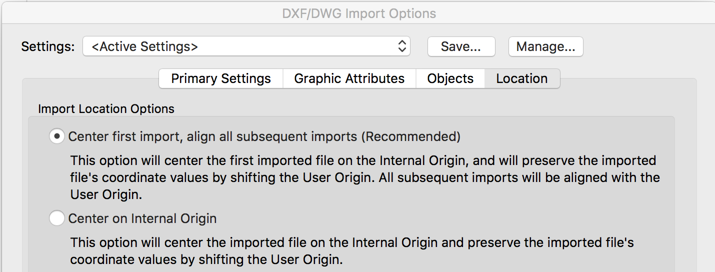
-
Snapping to geometry in referenced layers in rotated plan view not working VW2017
Kevin C replied to JJe's question in Troubleshooting
Just to hopefully finish this one off. None of my drawings are ever set up on a shifted user origin When drawing site layouts (masterplans), the base drawing is always brought in as a OS Map in its original location and using the original units - metres (which is coordinated to actual GPS coordinates). This will allow for a topographical survey to be directly reference in and it will be in the correct location. The house block symbols are inserted - These are drawn as close to the 0,0,0 as possible with the bottom LH corner of the block usually set at 0,0,0 It is common (and I would say good) practice to rotate the view so that offsets can be made and be sure that they are all on the same plane. also makes it easier for dimensioning and everything else if you don't have to skew your neck when looking at a drawing. By drawing this way - you can be sure that everything is in its correct location (relative to GPS) If I am setting up my drawings up wrongly - please tell me as I do not know how to set them up differently. -
Snapping to geometry in referenced layers in rotated plan view not working VW2017
Kevin C replied to JJe's question in Troubleshooting
@Art V The issue is with converted files - Ie live projects. I do not have the time to "test" scenarios - that is what the software development is for. For projects which are in an early design stage, yes workarounds are a possible solution as you do not need to get production information out to tender or site and have to worry about everything being coordinated. But for projects which are live and information has to be issued it is not acceptable for temporary solutions to be proposed. There are a couple of nice features in VW2017, but the bugs in the system at the moment mean to me that they are just not worth it. Take the resource browser for example, to use it to its full potential it it has to sit as a floating palette and take up a large portion of the workspace, but to use it on a day to day basis - it really has to be docked which means that access to the additional funtions is extremely limited - unless you have massive or multiple screens (I'm working of a 27" iMac). Also - what has happened to the startup interface - I don't want to see a hazed over desktop it is very annoying to the eyes - I want to be able to access my desktop when I don't have drawings open, leave it as clear space please or blank it out !! I was also very exited to see a specific handrail / railing tool as this is something which VW has been lacking for ever, until I tried it - it works well as a standalone tool but is useless for use inside a building if you want to link a stair and landing balustrade. Say you start at the bottom of a stair go up to top of the stair and continue along the landing and return into a wall, pretty standard stuff, but the tool does not attach between levels and stories, and will not go up a stair - WHY!!! I am very quickly coming to the conclusion that VW2017 in its current form is broken and I may have to export all my live projects back to 2016 and uninstall VW 2017 until this problem is sorted - Just as well the batch file conversion facility doesn't work this year or I would have been more angry with this upgrade than I am at the moment. -
Snapping to geometry in referenced layers in rotated plan view not working VW2017
Kevin C replied to JJe's question in Troubleshooting
I have the same problem as well referencing floorpans into a site layout and only being able to snap when the page orientation is set to 0 - This did not happen in VW 2015 or VW2016. I have checked and the site plan is geo-referenced (as it should be) and each of the houses are drawn at the origin points on their own file (or very close to). I could create a local coordinate system, but I am not convinced that that will fix an error in the software. Once you move off a grid, it is very easy to forget the transposed coordinates (especially if there is more than one person working on the project - as I have in my office). I would also be unable to issue setting out coordinates as the setting out coordinates are generated from the site plan which is based on the OS grid. Also when registering new properties with the keeper (Register of Scotland), I am required to issue a dwg file with all properties and boundaries located on an OS grid - so a local grid cannot be used. There is definitely a graphics problem with VW2017. -
2017 - Section viewport - component fill problem
Kevin C replied to Eric Mousse's question in Troubleshooting
I have this problem for all tiles and fills - problem still exists after changing display to best compatibility. If you switch between design and sheet layers, the sheet layer and output seems to be OK but the design layer is will change rotation all of its own accord. -
scheduled Unsupported Error when Importing rfa in VW 2017
Kevin C replied to rgcn's question in Known Issues
I am Stil unable to import any revit file apart form the smallest manufacturer's block. I have attached a standard file I received from a Revit trainer who I know but I still cannot open it - It just hangs at "importing elements - 99%" Can anyone else try and see if they can - Or is it just me?? (Included as a zip file as the uploader won't accept revit files. rac_basic_sample_project.zip -
Thanks Jim. Do you have an indicative release date for SP1?
-
Does that mean it is a Mac OS problem?
-
Jim In response: My account is an administrator No - Always standard install No errors during installation No Me - Read & Write / admin - Read only / everyone - Read only File attached iMac_-_Kevin_C.spx
-
Thanks, I will give this a go and let you know.
-
scheduled Unsupported Error when Importing rfa in VW 2017
Kevin C replied to rgcn's question in Known Issues
I haven't been able to import anything other than a manufacturer's product file as yet. The files I tried to import were around 15MB and VW just hung without importing them completely. What I have found with the graphics problem is that as soon as I seem to have an issue with odd fills and lines appearing and disappearing, losing zoom function - in other words complete hang-up of VW. I have to save the file, quit and restart VW and everything is OK. There is obviously a problem somewhere, and I think it is related to the graphics module. -
The libraries are the standard stock libraries stored on the computer. I haven't gone near the company libraries yet which are on the server so there are just the stock libraries which ship with VW.
-
Yes, quite a few bugs but there, but I wouldn't be getting the new Macbook Pro anyway. It is a lot of money for a glorified laptop and since my office runs full blown iMacs, there is no justification. I do have an ASUS N53S laptop which I use when WFH. Will see how 2017 does on that.

