Decoyman
-
Posts
48 -
Joined
-
Last visited
Content Type
Profiles
Forums
Events
Articles
Marionette
Store
Everything posted by Decoyman
-
That's the one! Thank you.
-
I have inadvertently changed the effect of double-clicking on a title block border so that the layout editor is opened. I can't find how to reverse this. IIRC the instructions are in the dialog box where the choice is made that no longer appears(!) Any guidance would be appreciated.
-
Thank you for your help, HE. "Clip Photo to Viewport Crop" worked (although it didn't clip properly until I closed and re-opened the file). For what it's worth, I also had to switch off the control lines ("Show Control Lines") to stop them appearing outside the borders of the crop. Rob
-
I drew a viewport crop and deleted the rectangle that Camera Match seems to create by default. I'm not sure I can crop the image itself from within Vectorworks.
-
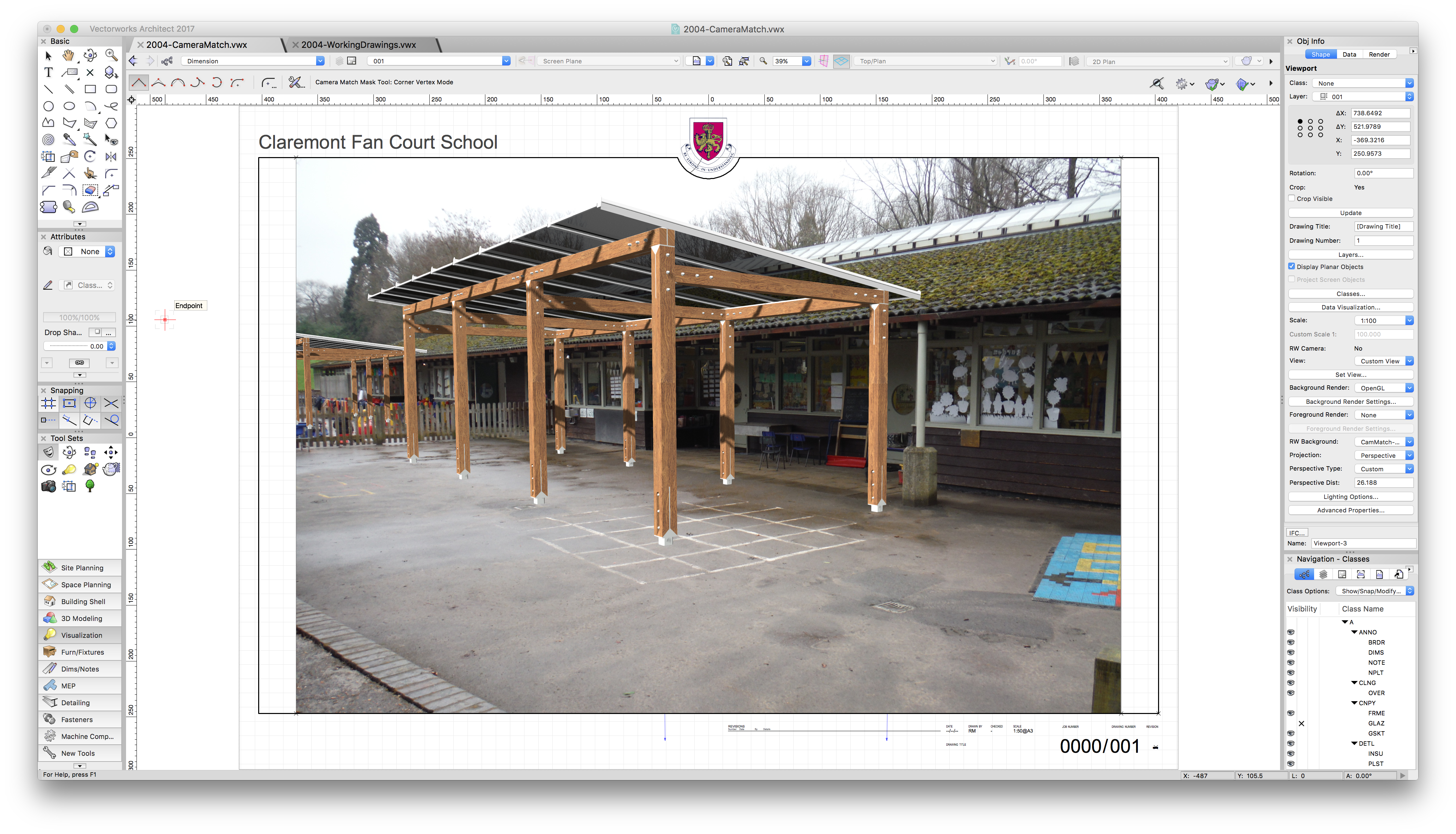
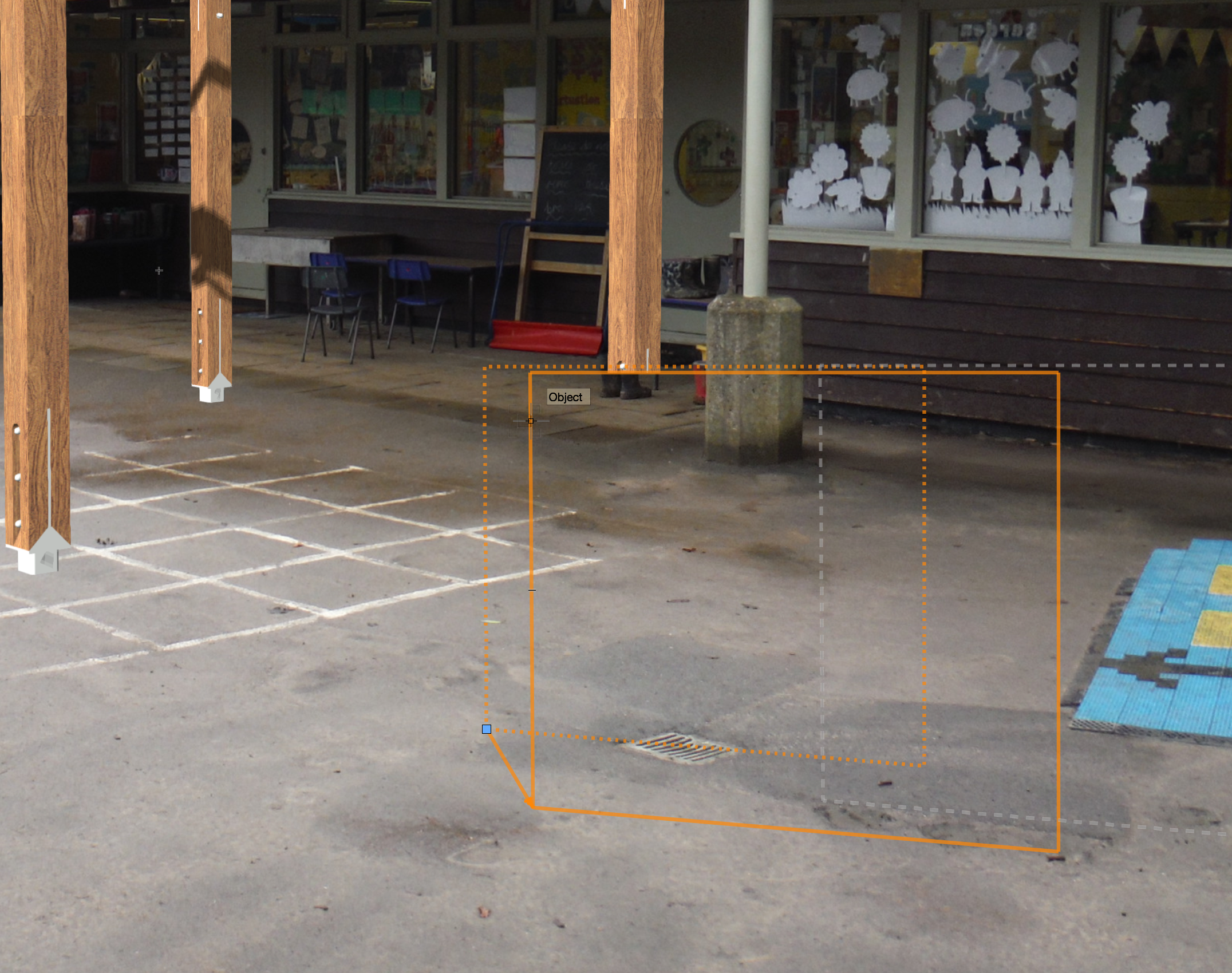
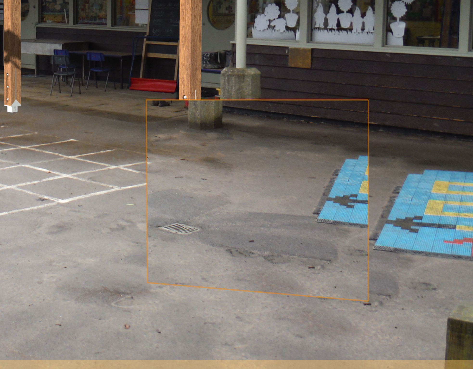
I have now made a new view, using a different image. This time I didn't scale it and the Camera Match Mask seems to be behaving itself. Strangely however, I now cannot get the image crop to work. You can see in the attached image that the crop is working up to a point, in that the area outside is fainter and the Camera Match guides are visible, but surely this should actually not be seen at all? Any thoughts? 2004-130-*.pdf
-
Thanks for the Acrobat tip. I managed to reduce a 38.4MB image to 3.1MB. Rob
-
If you mean have I adjusted the vanishing points and the target to get the drawn objects to match the photo then - yes. I haven't changed anything in this respect for some time, and certainly not subsequent to adding the mask. I did change the size of the image a couple of times early on and then "Set view to match" as necessary. This was also well before I added the mask. Perhaps this has confused Camera Match?
-
I've been trying out Camera Match on a small project I'm dealing with at the moment. The alignment tools are working very well - see my first attachment. However, I do seem to be having a problem using the Camera Match Mask. Drawing it is straightforward, but the resulting clip of overlaid photo is smaller than the section it's masking, and it's also displaced. I can kind of sort it out by converting the mask to a clone, scaling it by a factor of 1.2 and shifting the result, but this surely cannot be right. Does anyone have an idea of what I'm doing wrong (or is this a bug)? Rob


-
I get the same problem. Every time I render a sheet layer viewport using Open GL the out of memory error occurs. I'm working on an extension to an individual house - nothing complicated. There are three SLVs in the file which are rendered in this way, but it only takes rendering the first one of them to trigger the problem. Why?! I'm using VW 2014 SP2 on a 17" MacBookPro, 2009 vintage. Rob
-
I ran Cinebench R15 on my 4-year-old 17" MacBook Pro and got the following results: OpenGL 10.72 fps CPU 136 cb The OpenGL figure seems in line with Jim's test measurements, the CPU one completely at odds with them. Looking at the OpenGL result only it looks like I need a new computer! A very helpful thread, thank you.
-
DWorks said: This is interesting: do your clients/collaborators actually pay you to use your drawing as a base for theirs? I would love to be able to charge, after all, why should we do all the work, save everyone else money, and get nothing for it? However I have never come across an architect with the chutzpah to demand payment. What is other people's experience?
-
It's the Zoom that shows the problem. However, if you print the drawing you will certainly see it!
-
Attached is a screenshot of the file that you modified. It shows the section viewport and the ASP dialog Attributes pane. I have also turned on Zoom Line Thickness. I haven't applied any textures, other than the ones you have already added, however I note that the Background Render is set to Hidden Line, which is what I think one would normally use for this kind of drawing. As I said before, the class 'A Section Distance' has line weight of 0.05 and colour pale green. If VW was working properly all the OBSPs should be displayed using only these attributes. In fact you can see 'fat' dark green and pink lines, which ought not to be there.
-
Thanks Bryan! But you have the same problem that I (and, I think, Will) have: the 'Objects Beyond Section Plane' override, set through the Advanced Section Properties dialog has not replaced the objects' own attributes (which is what it's supposed to do) it has overlaid them. That is why you can see the pale green line through the middle of all the objects beyond the section plane. When I encountered this problem I was trying to show all the objects in elevation (as opposed to in section) in a common fine line. This is a common drawing convention, as I am sure you know. I couldn't achieve this, which I only understood when, instead of trying to replace the line weight, I tried to replace the line colour. This should be equally possible using the ASP dialog override, and this is what my example file demonstrates. The colour problem is more easily appreciated than the line weight problem, although it is the same (however, unless you have Zoom Line Thickness turned on it is difficult to appreciate on screen. Can you see what I am driving at? If you use the ASP dialog override, all the original colours and line weights of the objects in elevation should disappear. They don't. None of the do. Try setting the colour of the override class to white. If WVs is working as advertised and you are using a white background, all the objects in elevation should disappear. Instead you get a white line through the middle of the original colours.
-
Bryan, I've gone into this at some length. If you can show me how you managed to have no issues I would be very pleased to hear how you did it. The line weight of the class and whether the objects are set to use this is surely a red herring: the point of the exercise is to override all the line weight attributes for all the objects beyond the section plane using the Advanced Properties of the viewport. Therefore only the attributes of the overriding class should be visible in the viewport. In the file attached to my previous post the class 'A Section Distance' is used as the overriding class for objects beyond the section plane. This class has a line weight of 0.05 mm and a light green colour. The objects in the file have a variety of attributes (to test the problem), including some by class and some by object. In the screenshot attached to this post you can see the organisation dialog and part of a section viewport. The thin light green of 'A Section Distance' is clearly visible overlying the original attributes of the objects. See if you can make a new file without this problem and post it up here!
-
I think this is a bug. I've been having the same trouble with all objects (not specifically floor objects). What happens is that the objects beyond the section plane are drawn twice, once with the original attributes and again with the attributes of the overriding section style. You can see this if you set your 'objects beyond the section plane' section style to the finest line weight available (0.05) and a colour different from the original. Turn on Zoom Line Weights and zoom in. You should be able to see the fine coloured line overlaid on the thicker original lines. See the attached drawing to see what I mean.
-
It's on its way! Rob
-
Hi Tamsin, No - that only seems to work on sheet layer viewports. Rob (that one!)
-
I have referenced floor plans for a number of buildings into a master site plan using design layer viewports. All the buildings are steel framed and the floor plans show the structural grid with dimensions between gridlines. In the DLVs the text of the dimension is scaled to suit the floor plan, but the markers are scaled to the same size as the site plan. The result is absurdly over-sized markers. I can't turn the grid dimensions off because I need to show the gridlines and I don't want to separate the gridlines and the dimensions because this is inconvenient in the floor plan file. Surely there should be consistency in the scaling of referenced files? Does anyone have any suggestions? Rob
-
I'm having problems with wall features and end caps: if I add an end cap to a wall, give it the same class as the wall and set all its attributes to By Class the end cap doesn't show the same fill as the wall. If I then add a wall feature on the same basis the end cap miraculously acquires the correct fill, but the wall feature doesn't! Here are two attachments to show what I mean. Also: does anyone know how to get rid of the line between the cavity and the inner leaf where I have inserted the wall feature? Currently the wall feature is created by clip surface and the left side is set to wrap the cavity and the outer leaf. Looking forward to your helpful and edifying replies! Rob
-
To DWorks: no, not with Revit, with Vectorworks (of course!). To Vincent C and Christiaan: thanks for the kind words! The bricks are done using extract surface and applying a hatch. I tried using a tile, but it wouldn't show up in a Hidden Line render - not sure why. The 'siding', which is actually T&G boarding, was modelled in 3D. It's quite repetitive, so I was able to repeat panels as symbols to an extent. Each board has chamfered edges. I think it's the actual modelling of these elements which makes the render look reasonably believable. You might be interested to know that most of the building elements were modelled individually. I simply can't, for example, get windows and doors to look good using the standard tools. The road markings are 5 mm high extrudes to get them to look right(ish) in 3D. It seems like a lot of work, but once the bulk of it is done I can generate views from anywhere and have them look right. So far I've spent 140 hours on the project for everything, including several mind-numbing days wrestling with the Planning Portal (UK victims know what I mean!). Making the original model was probably a bit more than 100 of them. I am naively hoping that sections and construction details will come straight out of the model. We'll see.... Does anyone know whether Hidden Line can show cast shadows?
-
I modelled individual tiles on a recent project - textures and bump maps only work on Renderworks renders, I was using Hidden Line. What's more, modelling the tiles individually gives a more realistic profile at the verges. I discovered that you can perform a solid subtraction on a symbol without converting it first. perhaps everyone else knows this, but I didn't. It was a pain cutting tiles all the way up the hips, but apart from that, not too much trouble. I duplicated the tiles using the Move By Points tool to create one 'column' then I duplicated the 'column' using Duplicate Array in plan view. I haven't had particular problems rendering with the tiles switched on. I rendered the roof plan using Hidden Line, which avoided the hybrid draw-order issue that Christiaan mentions. Regards Rob
-
Tiles look different on design layer and sheet layer viewport
Decoyman replied to Christiaan's topic in General Discussion
Have you tried changing Tile Settings so that under Rotate "In Wall" and "Fit to Wall" are both selected? Rob -
If I show a plan in a sheet layer viewport I have the option through the Advanced Properties... button on the OIP to show or hide the wall components. If I show the wall components there is no problem, but if I hide them and if I have used Interior and/or Exterior Wall Details in windows or doors then the walls don't display properly: there are gaps the width of the jamb details on either side of the openings. The attached file hopefully shows what I mean. Is there a way of using the same plain fill for the jambs as for the rest of the walls? Incidentally I realise that I don't need to have any jamb details if the walls are plain filled, but this means drawing the windows twice or some other inefficient work around. I'm using v2012 on a MacBook Pro running Lion. Regards Rob
-
I filed a bug too....