


gester
-
Posts
667 -
Joined
-
Last visited
Content Type
Profiles
Forums
Events
Articles
Marionette
Store
Posts posted by gester
-
-
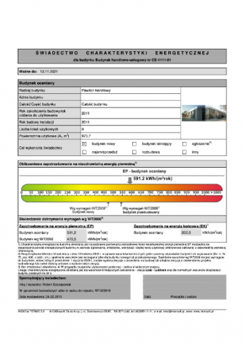
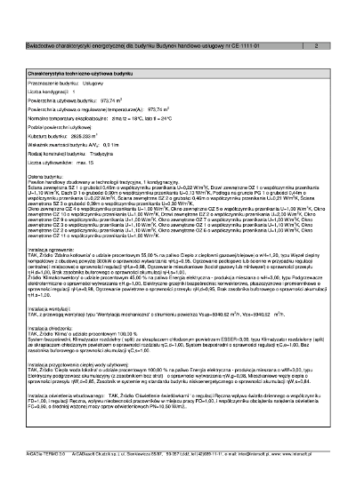
yeah, the polish certification document for the usage permit is formally standardised.
- the first page is the overall information of the building with the graphic display of its energy performance (enclosed is some older version before the tightening of the energy performance demand - the change is in the scope spread on the graphic ribbon - in this case the building doesn't comply with the requirements). the software can handle dwg imports, but not ifc models, so the calculations take approx. 90-95% of the creation time (a pretty cumbersome task, especially calculating walls and openings, depending on geographic directions), the rest is the adjustment of the installation systems. energy calculations are similar for all energy certification standards, what matters is the overall result, regarding particular requirements.
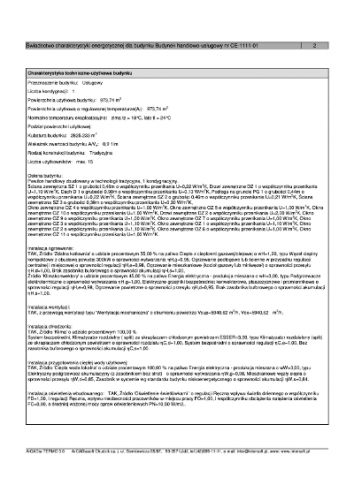
- second page is the description of the installation systems
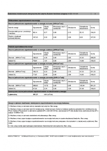
- third page is the calculations with improvement recommendations
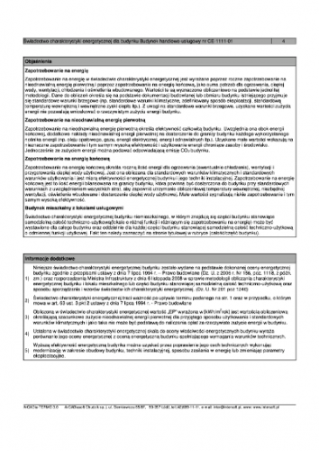
- the last page is the guides and notes - usually left as it is.
the certificate is valid for 10 years, and the creator is liable for any claims within this period. there's also a possibility to buy insurance for this scope, along with the professional designer's insurance.
is it somehow similar in the u.s.a.?
hth,
rob
-
you're welcome 🙂
-
i mean 'heating' or 'warm water preparation' of the main settings in energos. if you don't check (i.e. don't include) the existence of this system in your project, it will default to electric source.
rob
-
 1
1
-
-
On 10/15/2019 at 6:37 AM, _c_ said:
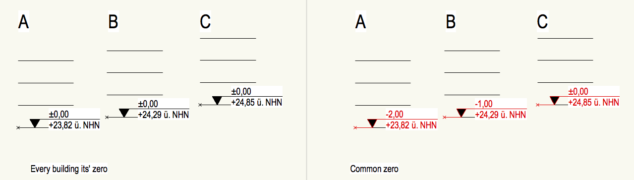
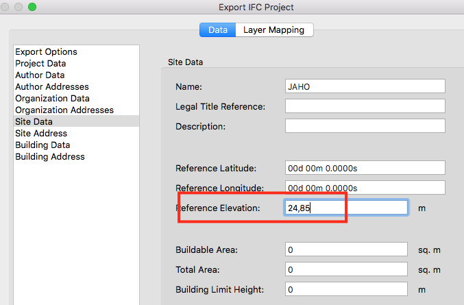
Ciao Zeno, do you use a common Z for all buildings or every building has its own project zero?
Accordingly, how do you set up the Reference Elevation in the Export IFC Project settings?


do you export one building or all of them in one ifc file?
it's not possible to have many 'zero' levels in one vw file, the zeno's approach is the right one.
you can but reference all edifices as separate design layers in a file with the whole plot setup (eg. all buildings are in 1:50 scale, and are referenced in the 1:500 raumordnungsplan)...
rob
-
12 hours ago, Nikolay Zhelyazkov said:
from what i gather (after some calculations) all settings default to electric systems. if you do not check the installation system energos assumes it's based on electricity.
-
it seems like you try to calculate the exact wall areas outside of the energos tool. the energy calculations are being done in the energos, though, so the 'external' calculations don't really matter in the energy calculations. i wonder how the nyc authorities accept those quantity reports?
i use the energos tool as 'designed energy calculations' which are required by the authorities for the building permit projects, but here in poland there's an another type of energy calculations for the usage permit. the latter one is defined by legislation and has a certain 4-page look with a special graphic display that can be obtained only in external sofwares for energy calculations for the polish market.
On 6/17/2020 at 5:51 PM, line-weight said:Some more specific questions:
1) I was interested in the bit about it being able to do u-value estimates for windows, based on me telling it the glass spec, frame type, etc. Does this take into account the number of framing members and their sizing or does it just provide a generic U-value for a window with overall size of X width and Y height? In other words, where the glazing U value is better than the framing U value, will I get a better result from a window that it just one perimeter frame and a big frame of glass, compared to a similar sized window which is subdivided into multiple casements and which has a different frame:glazing ratio?
the window producers provide the necessary data (separately for the frame, the glazing, and for the whole item), but in the the end the u-values are being (might be) typed in the window parameters manually, so you can shape the output by yourself.
-
hi,
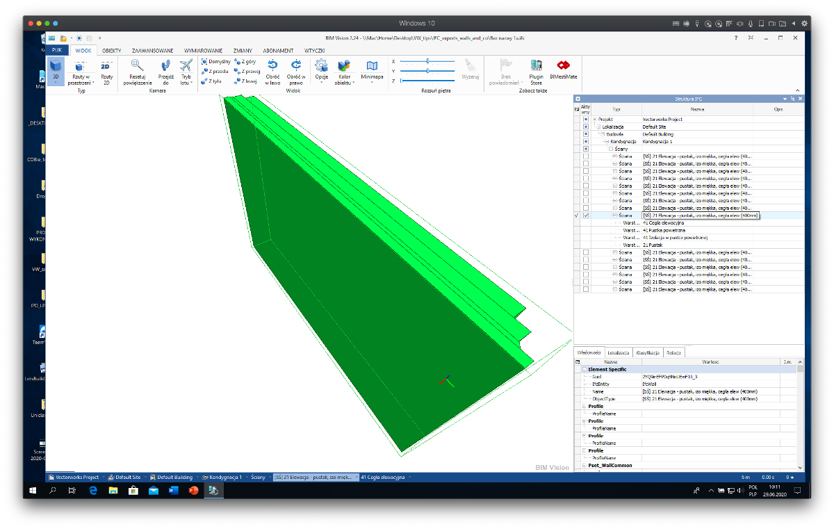
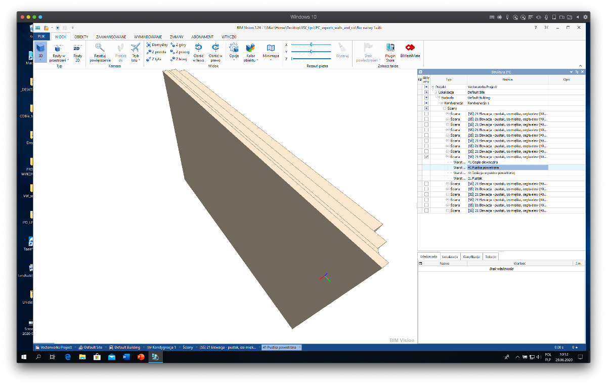
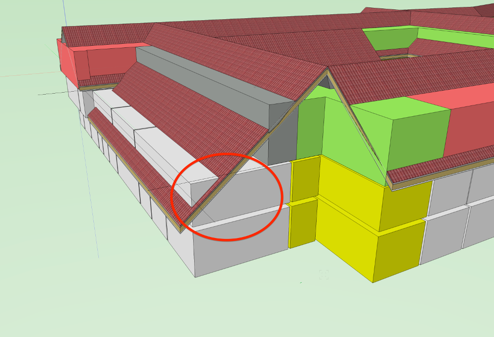
the ifc2x3 enabled exporting of composed objects (walls, slabs, roofs) by components. there's nothing like that in the ifc4 settings, so the components are not available for quantities' calculations in special softwares (screenshots below depict the bim vision imported ifc4).
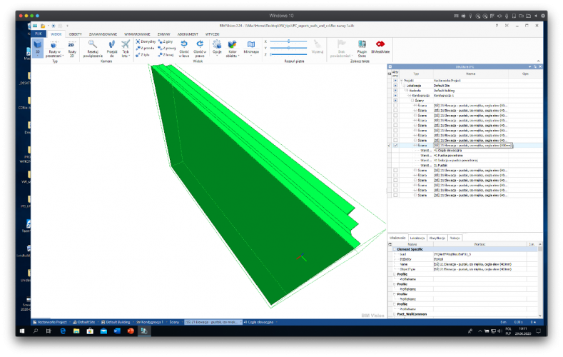
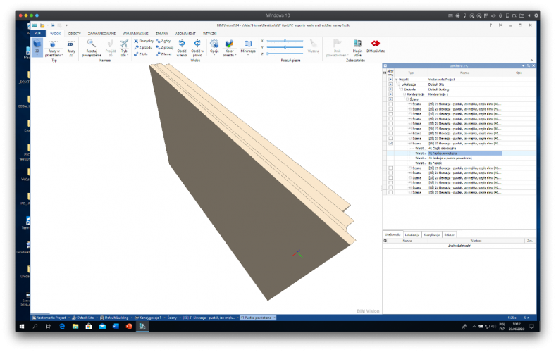
is it some step back, or is it by design?
and btw, is there the design transfer view export in the pipeline?
thanks,
rob
-
 1
1
-
-
seems a perfect solution, thanks a lot. i've missed this button in the first place 🙂
-
hi,
is there a way to calculate spaces' areas when there is a space height constraint?
in poland there is a norm (and an authority regulation) that the spaces are not counted at all when they have the height lower than 140 cm, the spaces with the height between 140 and 220 cm are counted with 50%, and for the heights above it's already 100% of the space area counted. it is pretty important for the projects with slanted roofs.
i've found the space record field value of net volume (counted), but apparently there's no way to divide this volume (and further on for space area) for different heights in order to calculate the spaces correctly.
i enclose the v2020 file with one space under the roof...
any help would be appreciated.
thanks,
rob
-
btw,
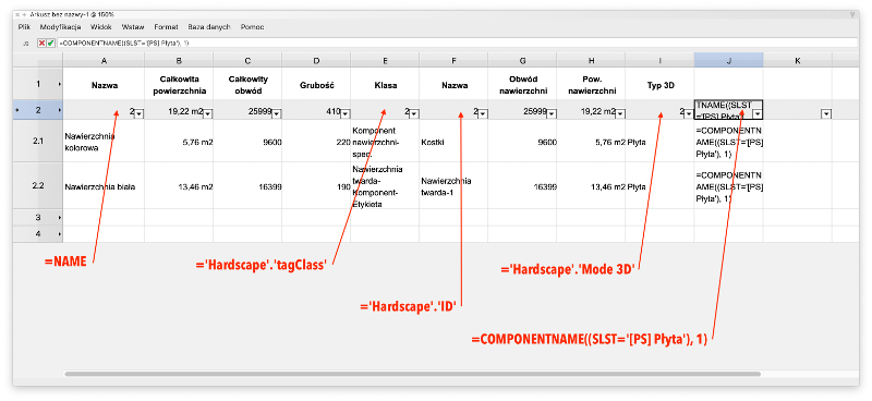
when i'm using the hardscape predefined record as db report criteria

the relevant fields don't contain any slab style data (the last column is a failed try)
-
hi pat, thanks for looking into it.
the thing is that the db call doesn't return the values that are hidden in the hardscape's slab for the 3d view. it just doesn't recognize this as components of the slab style.
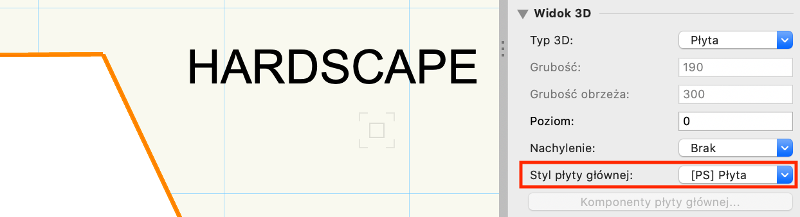
here's the hardscape oip screenshot:
here's the slab style
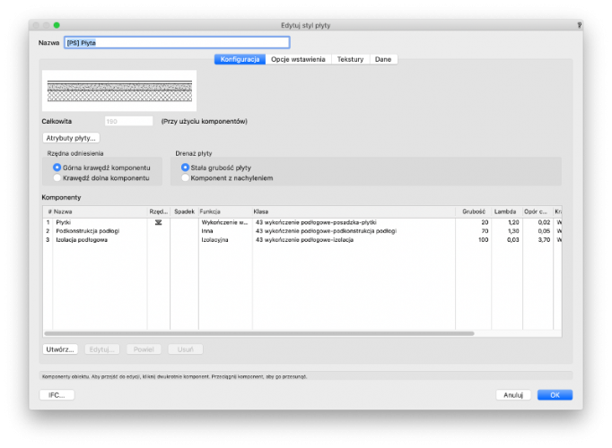
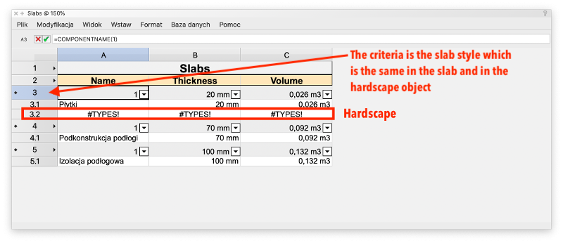
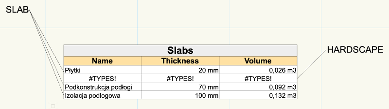
here's the resulting report, comparing two objects: one a slab, and another one a hardscape, both created from the same slab style

here's the report data:
am i doing anything wrong?
rob
-
hi,
is there a way to retrieve the properties of the slab style that has been used for the hardscape 3d creation?
the only value i get in the report is the name of the first component, no way to get to the bottom components.
the combination of the componentname and the criteria for the slab style with numeric indices don't work in the database call.
seems to be a black box...
anybody have a clue?
thanks
rob
-
hi,
1. is there a way to store the alternative cooordinates' system (the alternative angle) for future use?
2. is there a way to block the z-direction in perspective view (leaving only two vanishing points x, and y)?
thanks
rob
-
the trouble is that i can adjust the spaces that are completely under the roof, spaces that are partially under it i cannot 😞
edit: i've found out: it's the height and the bounding objects combined 🙂 it works 🙂
-
thanks, wes, cool 🙂
again, the darkest area is under the street lamp ;)
i thought, though, i could start my conceptual model with the spaces, but for the slopes i need the roofs first. ok, i can live with it.
thanks again for pointing it out.
rob
-
hi,
i believe to have read about a possibility to have space objects with slanted "roofs" in 3d view.
does anybody know how's about it?
we'd need it for macro bim (factor calculations by cubic metres of raw volume) along with the differentiation of spaces above 220cm height, between 140 and 220 cm (counted with 50%), and below 140 cm height, not counted at all for the finished space volume.
or should i post it in the wishlist?
bye,
rob
-
hi,
i remember to have read about a vectorworks ability to render images with two styles that merge into each other in a gradient mode.
i think it'd be two images on top of each other that have the opposite transparency gradient.
not the one present in the jonny pickup's vectorworks tip #437, but the one that comes from 100% transparency to the 100% of the image (_not_ of some mask !), in order to let the bottom layer to show up in the reversed way...
it this possible for a rendered viewport on a sheet layer?
thanks,
rob
-
i have checked the bounding box, and it displays proper values even for rotated objects (i.e. it doesn't simply take carthesian values)...
-
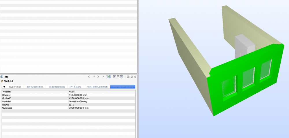
ok,
1. the result is the wall not having the components in the model tree (solibri model viewer), but the wall itself is getting all materials listed. i'll have to check if the components list correctly in 5d applications for cost calculations.
2. as a general notice: yesterday i was giving a workshop with somebody showing the ifc data mapping in archicad. the overall impression i've got from the participants was the simplicity of ifc assignment and mapping in vectorworks compared with archicad. of course, if you want to have it in a sophisticated way, the possibility to attach data is more developed in archicad, but it's a steep way to get acquainted with the procedure. you have to grab and insert data in many locations in the software.
3. btw, is there a way to reduce the amount of decimal places in the bounding box's x/y/z values? now i get 6 of them...
thanks,
rob
-
thanks, mihail, it makes sense 🙂
-
one more question: how to remove a custom pset (based on record) from the ifc data mapping list completely?
the more new records i use for psets, the more messed up the overall list gets...
rob
-
i take it back, this with the bounding box. it calculates the values _correctly_, not according to the carthesian system.
how about the components' listing?
-
hi mihail,
thanks, i see this, too 😉
as for the bounding box: the trouble is that only recognises carthesian dimensions (x/y/z), so if the wall is horizontal and vertical, the values are different for the length and thickness (they are swapped). i don't even try to think of walls under different angles 😉
polish window is a bit different as the us one, and it doesn't use styles. unfortunately the parametric object parameters' list is very short, way shorter than the us one.
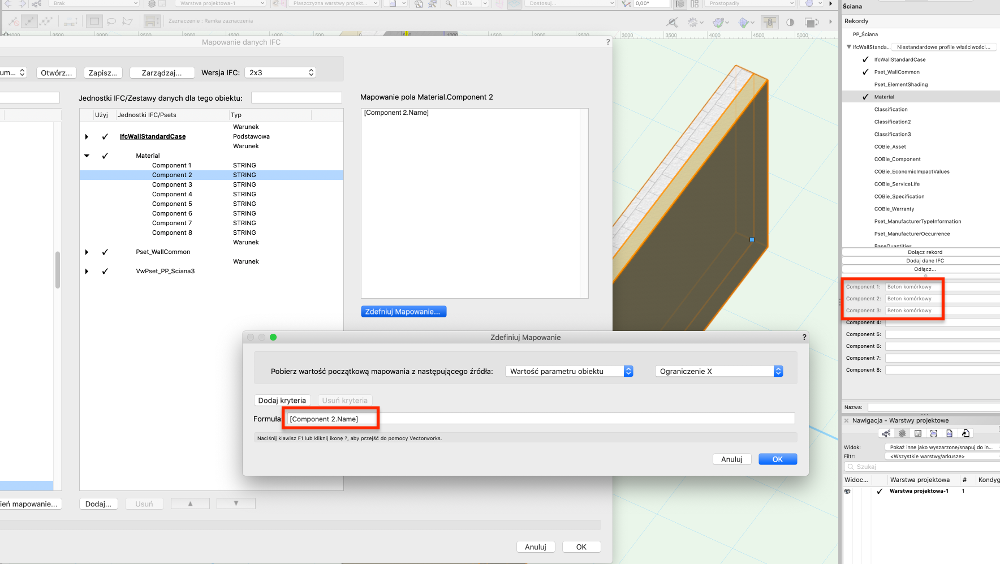
but here's another thing: the wall style.
i have a style with 3 components that i want to extract in the 'material' pset automatically.
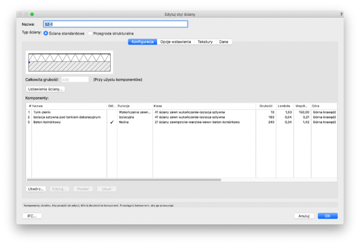
everything that the style can understand is the component, the first component. or am i missing the right formula? i've tried with component(x).name, componentx.name, all to no avail.

is there a solution for those 3 (different) values? and is there a chance to map a thickness value afterwards in the same data row?
i'm gradually getting nuts with it...
thanks,
rob
-
hi,
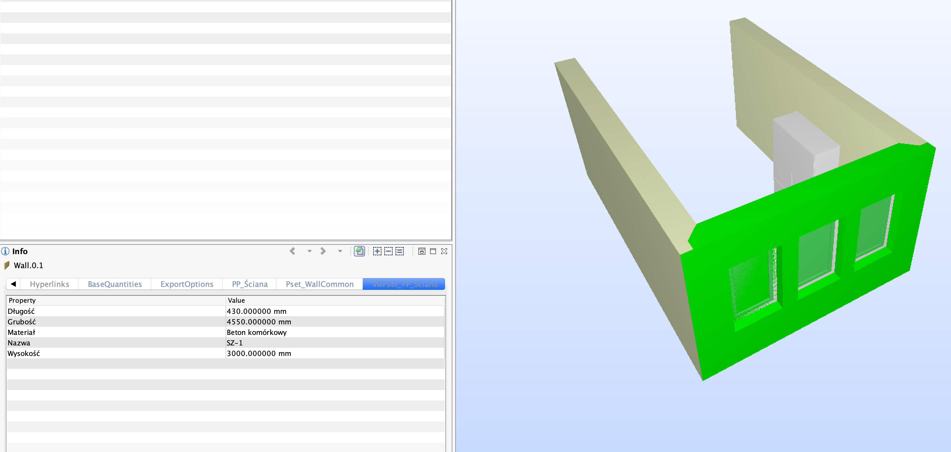
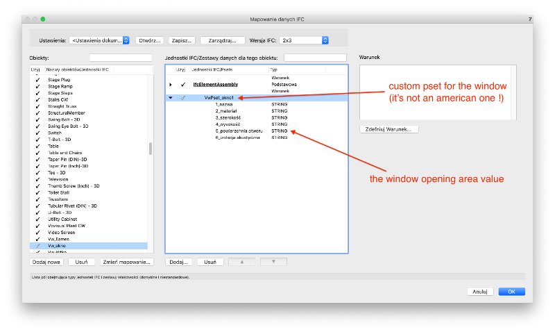
for some workshop i'm just adding a custom pset made from a record. the issue is to make a pset field for the wall with the value of all window openings.
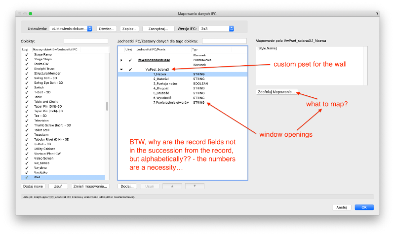
the window gets a separate custom pset.

is there a way to connect those values? i know the records are not that sophisticated as the database reports, but they use style and object data, maybe there's a way to solve this?
the window-record.field-value doesn't work in the wall pset...
thanks for any clue.
rob


Point cloud architectural modeling
in Workflows
Posted · Edited by gester
@Diego-Resuelvectorworks
you can also draw polygons in the plan view (2d) on point cloud basis, and then convert them to walls (create objects from shapes’ tool)...
or draw walls directly in 2d.
rob