


gester
-
Posts
667 -
Joined
-
Last visited
Content Type
Profiles
Forums
Events
Articles
Marionette
Store
Everything posted by gester
-
Basic tech needed for a 1 person business to collect Site data
gester replied to Eddie Haynes's topic in Site Design
so no chance for a direct, real-time editing of leica survey in vectorworks? vectorworks guys? rob -
i only had to remove one of the messed up objects and the whole cleared in an instant. but i dunno how or why rob
-
Basic tech needed for a 1 person business to collect Site data
gester replied to Eddie Haynes's topic in Site Design
hi guys, sorry for delays, and thanks for the feedback. the issue is the workflow. dxf works, but as disto has a pretty small display, you have to import dxfs in parts, in order to see anything on your computer while scanning. such autocad has a plugin, and you can see in real time what's going on with the survey. the above is what i've been told by the engineer working on vectorworks, and trying to utilize his leica. rob -
Basic tech needed for a 1 person business to collect Site data
gester replied to Eddie Haynes's topic in Site Design
sorry for reviving... some of the prospects are asking about the usage of leica disto (s910) and the right procedure to collect the survey data. what formats should they use, as dxf apparently doesn't work properly? are there any plugins needed? thanks. -
Smarter Wall Framer
gester replied to Tom Klaber's question in Wishlist - Feature and Content Requests
i second this wish. in poland there are walls that have wooden or metal frames in the thickness of the construction core (be it concrete or masonry), with thermal insulation outside and the plaster or gypsum cardboard inside. it'd be helpful to be able to calculate all elements separately, just for 5d in bim thanks. -
TWO-WAY FINISH SCHEDULE INSTRUCTIONS FOR SET-UP AND USE
gester replied to AlanW's question in Troubleshooting
hi alan, have you succeeded in finding the worksheet? i'm just scrutinizing the same issue... rob update: ok, i've found out, it's a localized version... -
ah, and another question: 3. the imported survey dwg should have the same units as the edifice project (either both cm or both m, in case of a metric system. when using centimetres, the world coordinates turn to centimetres value). does kml export have to be in metres, or can be in centimetres, too? thx, rob
-
sorry for reviving of this thread... 1. is there a possibility to reference an edifice project run as a shared project on a plot set up with world coordinates? i mean some mark for a 0,0 user origin of the referenced shared project inserted in some place on the plot with external infrastructure. our infrastructure engineers need the world coordinates for their workouts. 2. can such composed project (the edifice and its surrounding infrastructure) be exported to kml exactly and without further manipulation? thanks.
-
Placing a multi-level house on a DTM - best practice?
gester replied to skavan's topic in Architecture
hi, sorry for reviving this old thread... from what i gather from the thread and what i uderstand myself the most advocated option (for having both the edifice and the site model in one file) is to place the house on the real geographic level of the dtm, right? thanks for the feedback. rob -
an average file size of an architectural model in vw
gester replied to gester's topic in Architecture
alan, thanks for your thoughts. we have been talking about everything, cost being the reason they want to consider other software at all. but one of the issues is the file size, and thus their question. i'd like to know myself which file size is still operable in vectorworks, and how the 40'000 m sq project looks like in regard of the model size. -
an average file size of an architectural model in vw
gester replied to gester's topic in Architecture
yes, i know, but i discuss the issue with revit users willing to switch to vectorworks. they ask about the size because revit files tend to grow big, especially when all branches include, and not easy to navigate. so maybe there is some revit-vectorworks file sizes' comparison? maybe somebody has experience with such project size (30'000 - 40'000 msq, i believe it's some 300'000 to 400'000 sq ft.)? -
hi guys, as i've not encountered anything of that size in my own practice, can anybody report on a possible / usual / average file size of the architectural contribution for a 40'000 msq residential or office usage edifice? i know it depends on many factors, as i mean the delivery (final) status of the model. thanks for any hint. rob
-
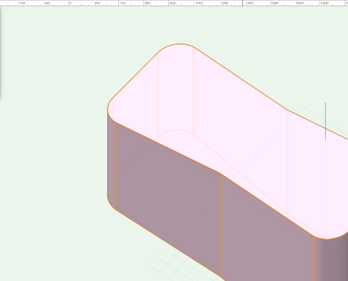
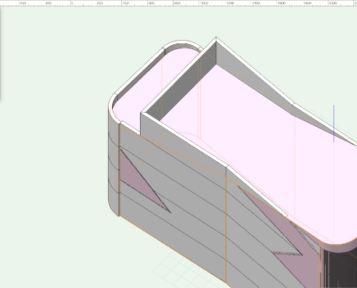
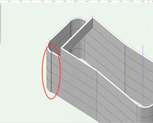
...to mesh not only 3d tools and the standard aec tools, but also marionette tools. generally there are two methods of designing: either space programming, or shapes' manipulation. of course mostly there are the combinations of both. we have adjacency matrix as a good start for space programming, and the massing model-to-floorplan functionality for 3d modelling come the edifice model. the latter one is not very optimal, as it has two flaws, at least: the resulting storey walls are not exactly closed when the shape is not angles only (screenshots), and we don't have slanted walls. in this way we can't freely model what we want... rob
-
michael/pat, ok, the difference between the calls is clear now. it means i have to choose the right criteria for the spreadsheet function call to get the result. thanks. rob
-
thanks, guys your suggestion for the database works, but for the spreadsheet doesn't. i have for the whole wall one class, and for the component another class. neither of the values for the class (c - criteria, wall nor component class) returns any viable result. and why is exactly the function call different for the spreadsheet and for the database row?
-
i can't get the compareabyname nor compareabyclass functions to work. can somebody clarify if it's only a database feature and how exactly to use it? thanks.
-
is this script still available? thanks
-
there's no 'tablet + mouse' option (which i'm currently using for cad/bim)...
-
wes, there are a few good thoughts behind the storey-level-system, but the result is somehow messed up. first of all: - we need storeys for the bim ifc-based energy calculations (exported with brep activated - space boundaries level 2) - we need a limited set of storey levels because of files' exchange between designers working on one edifice (but with work sharing this is not an issue anymore) now i think the best workaround begins with starting to think as a contractor's foreman: they need for each storey a clear level ('meterriss' for zoomer - it's a line drawn on the walls 1 meter above the future finished floor level). if somebody ever visited the building site, they know that no world levels are necessary, the contractor needs a clear 'z' height above or below the fixed level for each floor (storey). i would do the following: - set up each main storey level at the finished floor level. - add the design layers for elements, like walls, slabs, furnishing a.s.o. (matching the standard storey level names) at the appropriate main storey levels (= finished floor for ground floor, 1st storey, 2nd storey a.s.o.) - in this way all the elements can get the manual 'z' value above the finished floor, which is understandable for every construction worker - those values you can read from the pio. an example: a design layer for suspended ceilings has a level of the ground floor finished floor, if there are different suspended ceilings you can see their height above finished floor in the 'z' values in the pio - you don't have to calculate deltas. another advantage is that we can assign any number of design layers to a storey, they are all set up at finished floor level. - all other storey levels that don't have design layers attached may be used for the association of the, say, claddings, plasters, tiles, or similar building elements, so they may remain at levels other than the finished floor. rob
-
i was wondering how did you come on those almost 3k posts within 2.5 yrs, but it's the proof: you put everywhere your 2c, even when you don't really have much to say no offence, though your pluses are probably justified...
-
so as for now, the bcf manager only works when some 3rd party application generates a proper ifc feedback for the vectorworks file and saves it as a bcfzip. there's no automatic recognition of the geometry clash issues from within vectorworks, and the manual one is pretty cumbersome. btw, both buttons 'new' and 'close' don't do much, beside irrevocably clearing all existing topics by the 'new'. if the report is not saved, the information gets lost.
-
BIM | Goodbye Design Layers - Hello Super Layer
gester replied to Tom Klaber's topic in General Discussion
there's always a question if an app should continue to develop like it used to do, or just to write it from scratch facing the bim evolution. i also don't really believe a cad app may be that improved to serve the whole bim environment. even one of the youngest apps (revit) still has troubles with its over-parametrized approach. in this way we, as vw users, are really better off with the software's flexibility in the parameter settings, although it means to have to manually set up many things after they are already modelled - architects don't like such approach, as they are supposed to be artists, and not programmers. i'm really curious if the rewriting of the vectorworks' file format will bring more bim functionality into the application... rob -
BIM | Goodbye Design Layers - Hello Super Layer
gester replied to Tom Klaber's topic in General Discussion
why, ifc is a living system it's constantly improving. coming back to bricscad: i've always encountered compromises when it comes to engineering functionality. if something is further ahead, something lags behind. what is it in this case? textures, components, ifc data? -
BIM | Goodbye Design Layers - Hello Super Layer
gester replied to Tom Klaber's topic in General Discussion
ifc is a very well thought classification system, to suggest any modification would mean to have to co-work in the product room of the buildingsmart alliance. not a cheap endeavor, i'm afraid... -
BIM | Goodbye Design Layers - Hello Super Layer
gester replied to Tom Klaber's topic in General Discussion
ok, how do you want to show it in 2d drawings? you'll probably need the proper section level - and an adjustable one (higher or lower along the wall length where the stacked elements exist)...
