


DomC
-
Posts
604 -
Joined
-
Last visited
Content Type
Profiles
Forums
Events
Articles
Marionette
Store
Posts posted by DomC
-
-
The Function I use CreateChainDimension:
def create_chain_dim_vertical(intersection_points_sorted, x, offset, vp_scale): #standardly im text is left if there is no place between
	threshold_2_dimension, dimoff1, dimoff2, dimoff3 = create_globals(vp_scale , layer_scale , units)
	start = intersection_points_sorted[0]
	h1 = None; h_first = None
	prior_segment_length = 0
	prior_shifted_leftright = False; prior_shifted_up = False
	for i in range(len(intersection_points_sorted)-1):
		# startPt is always last endPt
		end = intersection_points_sorted[i + 1]
		segment_length = abs(end - start)
		if segment_length > epsilon:
			vs.LinearDim((x,start), (x,end), offset, 4, 769, True, 0.1)
			if data['b_debug_dim_color']: vs.SetPenFore(vs.LNewObj(), (65000,0,65000));
			color = (65000,0,65000)
			if i > 0:
				h2 = vs.LNewObj()
				if not vs.GetObjectVariableBoolean(h2,30): #Text hatte kein Platz
					if i < len(intersection_points_sorted)-2: #not last dimension
						start_next = intersection_points_sorted[i+1] #=endPt
						end_next = intersection_points_sorted[i+2]
						next_segment_length =  abs(end_next - start_next)
						if prior_segment_length < threshold_2_dimension and next_segment_length > threshold_2_dimension:
							vs.SetObjectVariableBoolean(h2,29,False)#unlock Text position
							vs.SetObjectVariableReal(h2,44,-0.1)#text shift
							vs.SetObjectVariableBoolean(h2,29,True)#calculate dim text
							color = (65000,0,0); prior_shifted_up = False
						elif prior_segment_length < threshold_2_dimension and next_segment_length < threshold_2_dimension and prior_shifted_leftright == False:
							vs.SetObjectVariableBoolean(h2,29,False)#unlock Text position
							vs.SetObjectVariableBoolean(h2,30,True)#Text inside
							vs.SetObjectVariableReal(h2,44,-0)#text shift
							color = (0,30000,30000); prior_shifted_up = False
						elif prior_segment_length < threshold_2_dimension and next_segment_length < threshold_2_dimension and prior_shifted_leftright == True:
							vs.SetObjectVariableBoolean(h2,29,False)#unlock Text position
							vs.SetObjectVariableBoolean(h2,30,True)#Text inside
							if not prior_shifted_up:
								vs.SetObjectVariableReal(h2,43,offset_up); prior_shifted_up = True; color = (0,65000,0)
							vs.SetObjectVariableReal(h2,44,-0); color = (0,0,65000)
					else:
						vs.SetObjectVariableBoolean(h2,29,False)#unlock Text position
						vs.SetObjectVariableReal(h2,44,-0.1)#text shift
						vs.SetObjectVariableBoolean(h2,29,True)#calculate dim text
					prior_shifted_leftright = True
				else:
					prior_shifted_leftright = False
				#prior_segment_unshifted = vs.GetObjectVariableBoolean(h2,30) #debug
				if data['b_debug_dim_color']: vs.SetPenFore(h2, color)
				vs.ResetObject(h2); #vs.SetPenFore(h2, (65000,0,0))
				vs.ResetObject(h1)
				h1 = vs.CreateChainDimension(h1, h2)

			else: #first dimension > move to left
				h1 = vs.LNewObj()#;vs.SetPenFore(h1, (65000,0,0))
				if not vs.GetObjectVariableBoolean(h1,30): #Text hatte keinen Platz
					vs.SetObjectVariableBoolean(h1,29,False)#unlock Text position
				vs.SetObjectVariableReal(h1,44,0);
				if data['b_debug_dim_color']: vs.SetPenFore(h1, (30000,0,30000))

			#vs.AlrtDialog(str(h1))
		prior_segment_length = abs(end - start)
		start = end
	chain_dims.append(h1)
-
Thanks for Feedback
2 hours ago, JBenghiat said:That said, the Compose command will do what you want without a script.
I will try with a DomMenuTextByName as a workaround, thanks
The complete Script has 800 lines (it reaches the limit of maximum size of a script), take a look here 🙂An incredible powerful Auto-Dimension Script
59 minutes ago, Pat Stanford said:for i in range(len(dimensions)-1):
The Second Script iterates through the length of dimensions. If I have the minimum of Objects (2) then length is 2
The loop starts with 0 and ends with 2-1 (1). If the loop would go till i == 1 i had an index of range with i+1. Different ways to do that with python.
-
Hi there
I want to join single dimensions in one chain dimension. So far it works but I have an undo issue. If I undo the script my single dimensions are deleted and I also get an undo alert in the log file.
My simple test with two dimensions:
h1 = vs.FSActLayer()
h2 = vs.NextSObj(h1)

hnew = vs.CreateChainDimension(h1, h2)
My function to join n-Numbers of single dimensions
dimensions = []

def getObj(h):
	dimensions.append(h)


vs.ForEachObject(getObj, "(NOTINDLVP & NOTINREFDLVP & (SEL=TRUE))")


h1 = dimensions[0]
for i in range(len(dimensions)-1):
	h1 = vs.CreateChainDimension(h1, dimensions[i+1])
The Scripts are working on selected objects for that test.
The Undo Alert I get:"ALERT: Invalid undo primitive detected: Imminent crash is possible. Object 0x7ff725723440 is being inserted after it has been modified or deleted.","type":"INFO"}
Also really it is an undo issue because Unto after script deletes my dimensions. Have I to handle the undo events in a Vector Script? -
@corbinhand
Have you already checked this out?
-
 1
1
-
-
4 hours ago, corbinhand said:
I am not able to view this dropdown in the OIP after wrapping the network. It seems like it's not possible.
Like I told, you need to run the network, which pulls the values from the table. then you have to deselect and reselect the node. And then the popup is there. but not on the wrapper or a Marionette PIO, because this Node has an input and nodes with an connected Input will not shown on the wrapper or a Marionette PlugIn.
Thats why option #2 is the only proper solution. The posted example is option #1. -
Hello
Solved by searching the Forum. Seems we need backward indexing to delete the choices. Here the working popup Dialog.
choices1 = ['choice1', 'choice2', 'choice3', 'choice4']
choices2 = ['choiceA', 'choiceB']


def CreateMyDialog():
	vs.dialogid = vs.CreateLayout('Dialog Name', 0, 'OK', 'Cancel')
	dialogID = vs.dialogid
	vs.CreateStaticText(dialogID, 10, 'Popup', 60 )

	vs.CreatePullDownMenu(dialogID, 11, 40)
	vs.CreateCheckBox(dialogID, 12, 'Change Popup')

	vs.SetFirstLayoutItem(dialogID, 10)
	vs.SetBelowItem(dialogID, 10, 11, 0, 1)
	vs.SetBelowItem(dialogID, 11, 12, 0, 1)

	return vs.RunLayoutDialogN(dialogID, Dialog_Handler, 0)

def Dialog_Handler(item, data):
	dialogID = vs.dialogid

	if item == 12255:  # enter Dialog 12255  -> 12256 exit dialog
		for i in range(len(choices1)):
			vs.AddChoice(dialogID, 11, choices1[i], i)

	if item == 12: #checkbox
		num_choices = vs.GetChoiceCount(dialogID, 11)
		for i in range(num_choices, -1, -1):
			vs.RemoveChoice(dialogID, 11, i)

		if data: #checkbox True
			for i in range(len(choices2)):
				vs.AddChoice(dialogID, 11, choices2[i], i)

		if not data: #checkbox False
			for i in range(len(choices1)):
				vs.AddChoice(dialogID, 11, choices1[i], i)


result = CreateMyDialog()
-
1
-
-
Hi
Thanks @Julian. seems we need backward indexing for deleting the choices.-
1
-
-
edit:
Found something in the Forum here. I will try to check this. -
Hello
Would be great if anybody could help me. At the end result I want to be able to exchange a popup's choices. What I am trying to do is, that I delete the items with vs.RemoveChoice()
and build it new with a loop through my choices. I think I make something wrong by indexing with "AddChoice" or "RemoveChoice" just remove the string not shorten the Choice Numbers.
My script:
choices1 = ['choice1', 'choice2', 'choice3', 'choice4']
choices2 = ['choiceA', 'choiceB']


def CreateMyDialog():
	vs.dialogid = vs.CreateLayout('Dialog Name', 0, 'OK', 'Cancel')
	dialogID = vs.dialogid
	vs.CreateStaticText(dialogID, 10, 'Popup', 60 )

	vs.CreatePullDownMenu(dialogID, 11, 40)
	vs.CreateCheckBox(dialogID, 12, 'Change Popup')

	vs.SetFirstLayoutItem(dialogID, 10)
	vs.SetBelowItem(dialogID, 10, 11, 0, 1)
	vs.SetBelowItem(dialogID, 11, 12, 0, 1)

	return vs.RunLayoutDialogN(dialogID, Dialog_Handler, 0)

def Dialog_Handler(item, data):
	dialogID = vs.dialogid

	if item == 12255:  # enter Dialog 12255  -> 12256 exit dialog
		for i in range(len(choices1)):
			vs.AddChoice(dialogID, 11, choices1[i], i)

	if item == 12: #checkbox
		if data: #checkbox True
			num_choices = vs.GetChoiceCount(dialogID, 11)
			for i in range(num_choices):
				vs.RemoveChoice(dialogID, 11, i)

			for i in range(len(choices2)):
				vs.AddChoice(dialogID, 11, choices2[i], i)

		if not data: #checkbox False
			num_choices = vs.GetChoiceCount(dialogID, 11)
			for i in range(num_choices):
				vs.RemoveChoice(dialogID, 11, i)

			for i in range(len(choices1)):
				vs.AddChoice(dialogID, 11, choices1[i], i)


result = CreateMyDialog()
-
Like I told I do not work on that node, just a proof of concept and you had to edit the node code to make it usable. I think I want to provide a useful node maybe but not now.
However, the popup delivers an index and this index corresponding to the lines in the popup and the lines in the worksheet. You could do this to return the value of popup instead of index.
self.Params.output.value = j['data'][0]['popupChoices'][input]['text']
Or this, to return the line from the worksheet (which is the better option)
self.Params.output.value = lines[input]
input is the popup index.-
2
-
 1
1
-
-
Hello
The Custom Popup Widget from the Nodes, are generated by editing the Nodes. There are some special Popups which are handled by the Marionette core itself. As example the class popup. If you add classes the popup will contain that new class.
You can generate the popup items with a script from a worksheet. No question. Lets say, you can say the popup the have those items from the worksheet by script. You have to run the script to deliver the items of the popup. If you click on a popup with items generated like this and you do not run the network your popup has no data because no script was executet. So what can be done without manipulationg the core too much:
1. Create a node with a popup, which takes items from the input. You have to run the network bevor the items are activated.
(Example Attached)
2. Create a dialog push Button or a Dialog which runs when the script runs.
3. Dis Dialog has his own popup and can be generated with every functionality of script engine.
4. Having a seperate script (as example in the worksheet), which will push the worksheet changes to the node popups widgets.
probably it could be possible to manipulate or generate the popup in the Marionette class but it is not something I grabbed before and I guess I would not provide public.
So the best option in my opinion is #2, where we have a push button with the popup. The popup will always be up to date. Maybe an issue, if the push-button is nested too deep in wrappers and Object Nodes. So if you do something, always check if it works in your final product. But also this could be an issue with the other variants.
Here the example, how to overwrite the node-popup from outside. Also this technique is provided a long time ago in the gallery. The Node is just a proof of concept, you cant use it without edit the node code for your own usage. I try to make an Example in the Gallery, which takes a worksheet input and have a push button for choosing the popup. Because this sounds for me very useful for many Marionette users and developpers.
the interesting think is, that there will be two popup. The first popup will allow to filter the items of the second popup. I think this is not a big thing but as I can remember last Time i made a popup with changing items, i did not known how to eliminate the vestige of deleted popup items.
-
2
-
1
-
-
Hi
I think this can be made by scripts and/or a Marionette Nodes. I think with getRecordField and with getObjectVariable you can pull the requested values out of a viewport, if you know their IDs.
The Advantage of a Standard Label or Data Tag is, that it has a perfect Link to the viewport and a User Interface to link/delink to an object. This could be made with tricks for sure with a Marionette but without a good UI and with supporting scripts etc. So I recommend to try to make your object with the DataTag. Which I think this is all makable with the DataTag except the "arrow symbol" maybe.
As Example the Viewport Scale you can pull out with the following formula in a Data-Tag:
Scale: 1:#WS_ObjectData('Object Variable', 1003)#
Source:
https://developer.vectorworks.net/index.php/Worksheet_Functions
Some of the Object Variable of a Viewport (You can see them with the Methodes mentioned above):
QuoteSetObjectVariableReal (viewportHandle,1003,20);
SetObjectVariableInt (viewportHandle,1000,6);
SetObjectVariableInt (viewportHandle,1001,0);
SetObjectVariableReal (viewportHandle,1002,9.76);
SetObjectVariableBoolean (viewportHandle,1005,TRUE);
SetObjectVariableLongInt (viewportHandle,1006,0);The Rest you can get from the Data-Tag Standard Variables.
The Method to find Object Variables is the Script Reference or exporting a Drawing with one viewport as a text Format and search the Viewport's "SetObjectVariables". Change one value of the viewport and export again and see, what changes. Or you can use the "SearchObjectVariable" Marionette. Must be here in the forum but can't find it right know.
The Data-Tag is a very powerful Drawing label. Only disadvantage is missing links between VP and Labels and no Links in Exported PDFs.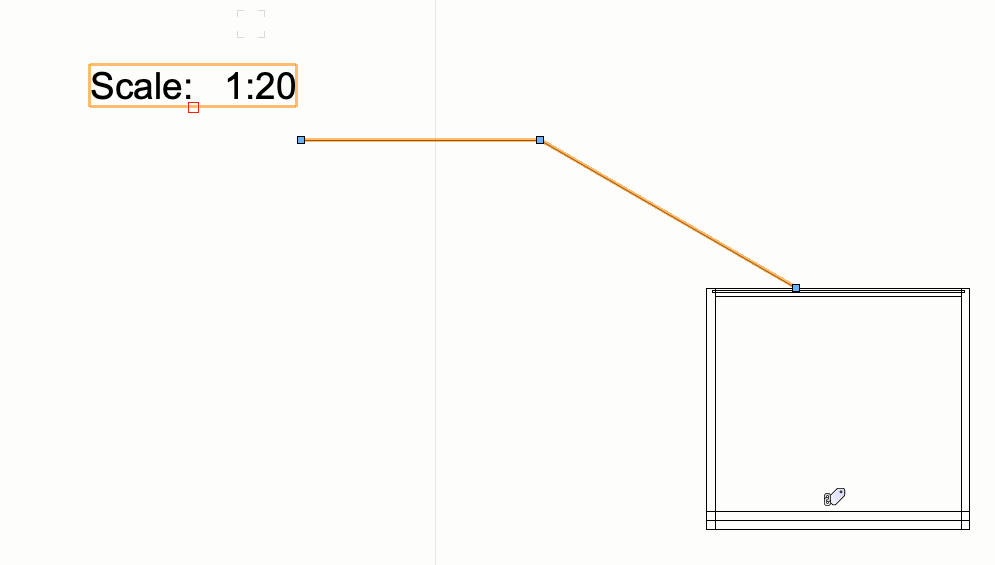
-
Hi
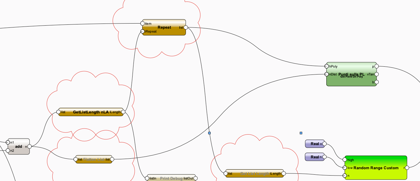
You are quite near at the solution. You need to repeat every poly handle as many times as there are points on that polyline. To get the number of points you have to get the number of items in every list you created with the chunk by list node. Also here you need a node, that is not standard. I do not know to do it with standard nodes. I think chunk by list and length of sublists is something, that I is really missed by repeating things on n objects.
The Node you can see GetListLength ist the standard Node but the line "this.SetListAbsorb()" is commented with a #. Different ways to solve that I think.
Nice Example.
-
- Popular Post
- Popular Post
Merry Christmas for all Vectorworks Nerds 🙂
-
5
-
 2
2
-
7
-
Hi
The Field name of "Gesamt Breite" ist 'Width' not "Breite". If you change that, you will get the right object.
If you set a name of the object, you change the name on the object info on the very buttom. Not the Cabinet Name. The Cabinet Name ist generated by a higher "act of nature" we are not able to write that Name field with a Script.
Also ungroup I would not use. Because your Symbol is inserted as a PIO. The group around every marionette-created geometry you cant eliminate with the ungroup node. I think this could be changed with the node itself "linkedGeometry"
This here, created the group: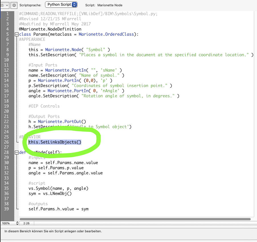
-
As I understand, you want something like global variables for the PIOs on the Document. Like Title Block Project Data.
There are several possibilities. I think it depends on what you can handle yourself. 3 Examples of Strategies:
1. You could get the values from a Record handle (the record definition itself not from an Object > It takes the default value). So you had a central control over those values.
2. You could push the values (with a Dialog) directly to the Marionette PIOs
3. Take the value from a worksheet
This depends how your Marionette-Code is designed.
I guess SimA - Method (Method 1?) would be the best option.
To the second Methode. Maybe this is the hardest one because changing the OIP of Marionette is not as simple like with Standard PIOs. There is an Example in the Gallery to make this or you could code A dialog-Window Enter the Value and Push them on your Objects. For myself I use that method to backup values from the marionette on a record. So the script is updated I am able to pull the values if necessary from that record.
Code something like this:import json #Globals recName = 'MarionetteObject3D' #recName = 'MarionetteObject2D'# Check, the Marionette Rec-Name for your Marionette PIOs fldName = 'NodeDef_OIPControls' #collect Objects objs = [] def getObj(h): objs.append(h) criteria = "(NOTINDLVP & NOTINREFDLVP & (C='MarionetteObjects'))" vs.ForEachObject(getObj, criteria) OIP_Name = 'Mauerlicht' #Name of the Parameter OIP_value = 1200 #value of the Parameter for obj in objs: sOld = vs.GetRField(obj, recName, fldName) #vs.AlrtDialog(str(sOld)) j = json.loads(sOld) for OIP_field in j['data']: name = OIP_field['varName'] if OIP_Name in name: value = OIP_field['value'] OIP_field['value'] = OIP_value vs.SetRField(obj, recName, fldName, json.dumps(j)) vs.ResetObject(obj)
-
Hello
I posted a Marionette example, that installs a python pillow library from a wheel file with Vectorworks 2022.Now I stuck on Windows.
-
1
-
-
- Popular Post
- Popular Post
Thanks Vectorworks Inc. for the great job on our favourite core-features in 2022. That's worth a small attention from my side.
(Sound Featuring Garage Band, Organic Tower inspired by Johanna Grüneberg, Marie Brackmann (Detmold University, Markus Graf)-
9
-
3
-
Fantastic Julian this is a very reliable solution, Thank you. I implemented this way:
dim = vs.FSActLayer()

def GetDimAngle(h1):
    h2 = vs.FIn3D(h1)
    DimAngle = 0
    while h2 != vs.Handle(0):
        if vs.GetTypeN(h2) == 2:
            BOOLEAN, style, angle, size, width, thicknessBasis, thickness, visibility = vs.GetObjBeginningMarker(h2)
            if style:
                DimAngle =  round(vs.HAngle(h2),0)
        h2 = vs.NextObj(h2)
    return DimAngle

DimAngle = GetDimAngle(dim)
vs.AlrtDialog(str(DimAngle))
-
1
-
-
Dimension Direction.vwx
Hello
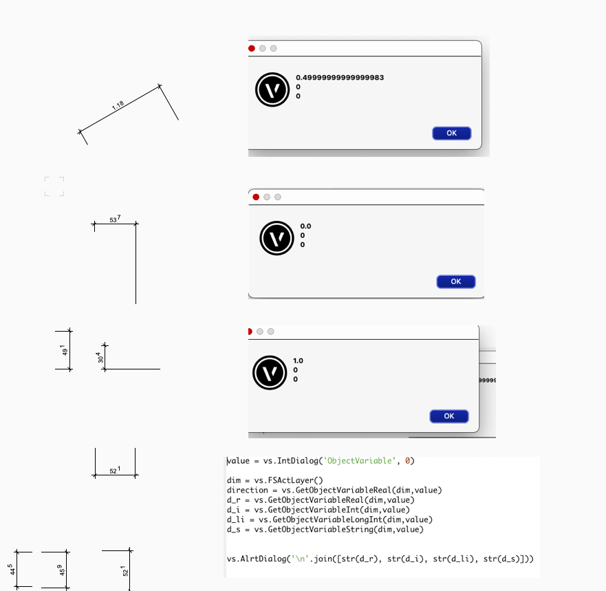
I am able to check if a Dimension is vertical or horizontal withdirection = vs.GetObjectVariableReal(dim,value)On my mac version, it returns 0 for horizontal and 1.0 or -1.0 for vertical Dimensions. Unfortunately this seems not to work on Windows. There is always 0.0.
I could test if xDiff is bigger than yDiff (of the Dimension Points) an decide it is horizontal but this can result in errors with some dimensions.Anyone has an Idea to get that information reliable?
-
What about this:
def IsTagged(h):
    result = False;
    num = vs.GetNumAssociations(h)
    assH = None
    assKind = None
    value = None
    i = 0;
    while(i < num and result == False):
      assH, assKind, value = vs.GetAssociation(h, i);
      if (assKind == 37):
        result = True;
        i = i + 1;
        return result, assH;
This would help finding Tagged Object. This was some I found in the Forum here. It works in a Marionette Object, which is inside a DataTag to find the tagged Object. So I think you could loop all Objects and check with vs.GetAssociation() type 37. Then you have the Tag and could check the Kind of Tag.
-
1
-
-
Hello
The Object looks here as it should. So the crunchpoint will be, what is the difference between the attached file and the files you have issues with this object. I would check the following:
1. Distance to the drawing center (Vectorworks origin)
2. Model view on?
3. If you delete all other objects out of the model how your Marionette looks then4. If the Object looks like the left picture. Will it look all right after refresh, reopen the file or copy paste on another layer or copy paste to the origin. Or does it not work at all so it cal be reproduced always or just after working a while?
-
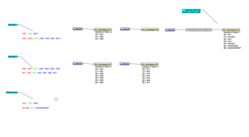
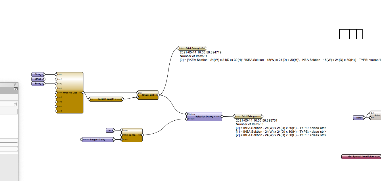
The Popup list you generate delivers 3 string variables into the network. But for a popup, you need those 3 strings nested into a list as Example ['choice1', 'choice2', 'choice3']
If you run the node without list absorbing, the input with the choice would deliver 'choice1' the first time the node runs, 'choice2' the second time etc. that's how the Marionette Data-Flow works. The node repeats as many times as one input delivers values.
"list absorb", is merging all inputs into a sequence and the node just run once. So the popup there will work. But because the node run just one, your dialog run just once. you could loop through the number of dialog you want to have with the integer input you have in the node itself. Or just leave the node how it is and merge the popup into one list. I would recommend this:
-
2
-
-
Hi
I am close before using a custom node and I thought, this time I ask before I create a new custom node 🙂
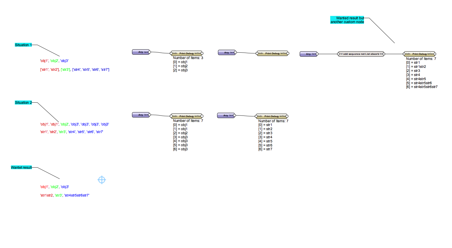
I have two corresponding data flows in two wires. I want to add items of the second wire by counting the items in first wire.
'obj1', 'obj1', 'obj2', 'obj3', 'obj3', 'obj3', 'obj3'
second wire is:
'str1', 'str2', 'str3', 'str4', 'str5', 'str6', 'str7'
Somebody knows how to concatenate the strings of the second wire corresponding to the count of the items in wire 1?'str1str2', 'str3', 'str4str5str6str7'
In a second scenario, I have already grouped the second wire in lists of the lenght of counts of the items in wire1'obj1', 'obj2', 'obj3'
['str1', 'str2'], ['str3'], ['str4', 'str5', 'str6', 'str7']
I repead: It is no problem to solve that with python, but with standard nodes I need an idea.
Import Symbol from Workgroup Libraries
in Python Scripting
Posted · Edited by DomC
It should work with something like this:
(Not tested but should work)
To grab several res files in a folder and his sub-folders:
Then you could loop through several res files:
If you have issues with the path, maybe try: