


DomC
-
Posts
605 -
Joined
-
Last visited
Content Type
Profiles
Forums
Events
Articles
Marionette
Store
Posts posted by DomC
-
-
Hello
There are some old threads for this theme but it seems, there is no proper solution.
I also searching for an elegant solution to make fillet on NURBS Curves. As the Tool works fantastic, by script it seems to be not so trivial. Maybe because we need to combine somehow several segment of NURBS and not all parameters can be edited by script.
So far I tinkered an approximated solution, which seems to work for my usecase it is exact enough and works but somehow not pleased yet for nitpicker like me and many of us 🙂 Target is to model filled NURBS for modeling pipes without using compose as menu command.
The Script:
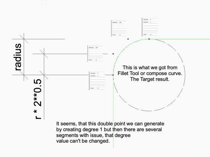
The calculation of the control points is exact. Also think about to stop pipe, insert a corner segment with right rotation (because calculation of the plane and points already done in this script) Also this could improve dramatically level of detail instead of a path extrude, which anyway have some issues when profile is bigger than radius.
It normalize the segment line and generates offset points from the vertex points. One control point with offset from the corner point with diameter and another control point diameter * (2**0.5 -1). The same as we got with the filled tool. The issue seems to be creating a "double" point with ends line segment to a radius NURBS. We get that with the tool but by script it is still a secret. I "solved" by giving a big weight (10) at the end of the line segment and weight 1 at the control points. It draws nearly an exact radius.
I hope maybe join again the thema and help improving the solution or can use the existing approximative method.
import math

sqr2 = 0.41421356237 #faster to have constante value instead of calculation 2**0.5 several times I guess
def point_on_line_3D(p1, p2, d): #3d Points d = distance from p1 to p2

	x1, y1, z1 = p1
	x2, y2, z2 = p2

	# a little long but it just substract p1 from p2, then normalize and then multiply with new lengt and add to old point
	c = vs.Distance3D(x1, y1, z1, x2, y2, z2)

	new_pt = ((x2 - x1) / c * d + x1,  (y2- y1) / c * d + y1 , (z2 - z1) / c * d + z1)

	return new_pt

nurbsObj = vs.FSActLayer() # take care to select a NURBS curve

radius = 100
segments = []

points = []
segmentCnt = vs.NurbsCurveGetNumPieces(nurbsObj)
for segm in range(0, segmentCnt): # python range is always one less than pascal
	pts = []
	vtxCnt = vs.NurbsGetNumPts(nurbsObj, segm)
	num_knot = vs.NurbsNumKnots(nurbsObj, segm)
	for vtx in range(0, vtxCnt): # python range is always one less than pascal
		v = vs.NurbsGetPt3D(nurbsObj, segm, vtx)
		pts.append(v)

		if vtx < vtxCnt - 1: #some code of the developper wiki
			p1 = v
			p2 = vs.NurbsGetPt3D(nurbsObj, segm, vtx+1)

			#vs.Locus3D(p1); points.append(p1) #corner point
			p = point_on_line_3D(p1, p2, radius*sqr2)
			points.append([p,1]); #points.append(p)
			p = point_on_line_3D(p1, p2, radius) #start radius point
			points.append([p,10]);


			p = point_on_line_3D(p2, p1, radius) #start radius point
			points.append([p,10])
			p = point_on_line_3D(p2, p1, radius*sqr2)
			points.append([p,1]); #points.append(p)


	segments.append([vtxCnt, num_knot, pts])

new_curve = vs.CreateNurbsCurve(points[0][0][0],points[0][0][1],points[0][0][2],True,3);

for i in range(1, len(points)):
	p, weight = points[i]
	vs.AddVertex3D(new_curve,  p)
	vs.NurbsSetWeight(new_curve, 0, i, weight)
	#vs.Locus3D(p)


vs.DrawNurbsObject(new_curve)
vs.ReDraw()
num_knots = vs.NurbsNumKnots(new_curve, 0)

for i in range(num_knots-3):
	pass

-
Oh, direct before my very eyes. Thank you so much, that works perfectly!
-
 1
1
-
-
Hello
Someone knows the secret of tagging an object with the DataTag by script? Seems to be not so easy.
So far my researches:
1. Read the ASSKINDs of Object and DataTag. It shows me:37 for the Data-Tag 36 for the Tagged Object
obj1 = vs.FSActLayer()
num = vs.GetNumAssociations(obj1)

out_str = 'Associations\r'
for i in range(num):
    v = str(vs.GetAssociation(obj1, i))
    out_str += str(v)+'\r'

vs.Message(out_str)
2. Further Assiciationsobj1 = vs.FSActLayer() obj2 = vs.NextSObj(obj1) result = vs.AddAssociation(obj1, 17, obj2) #4(deleted if delete), 5(reset if deleted) 17(?) vs.HMove(obj1, 1,0)
3. Remove Associations
obj1 = vs.FSActLayer()
#stempel = vs.GetObject('stempel')

num = vs.GetNumAssociations(obj1)
out_str = 'Associations\r'
for i in range(num):
    ioTargetObj, inKind, value = vs.GetAssociation(obj1, i)
    vs.RemoveAssociation(obj1, inKind, ioTargetObj)
4. Maybe with a constraint?
h1 = vs.Handle(0)
h2 = vs.GetObject('line1')
h3 = vs.GetObject('symbol1')


if h2 != vs.Handle(0):
    p2 = vs.Get2DPt(h2, 0)
    x1, y1 = vs.HCenter(h3)
    obj, index, containedObj = vs.GetClosestPt( h3, x1, y1)
    vs.AlrtDialog(str([obj, index, containedObj, h1, h2, h3])) #obj1 and h1 are the same contObj1 is None
    bool = vs.SetBinaryConstraint(1, h3, h2, index, -1, 1, -1, containedObj, 0)

if h2 != vs.Handle(0) and h3 != vs.Handle(0):
    bool = vs.HasConstraint(h2)
    vs.AlrtDialog(str(bool))
This works for a line and a symbol. Maybe this works with data-tags and object also if we could find the right arguments.
-
The Rendering in VW Design Layer:

Rendering in Viewport:
(Rendering is a little brighter because of image effect)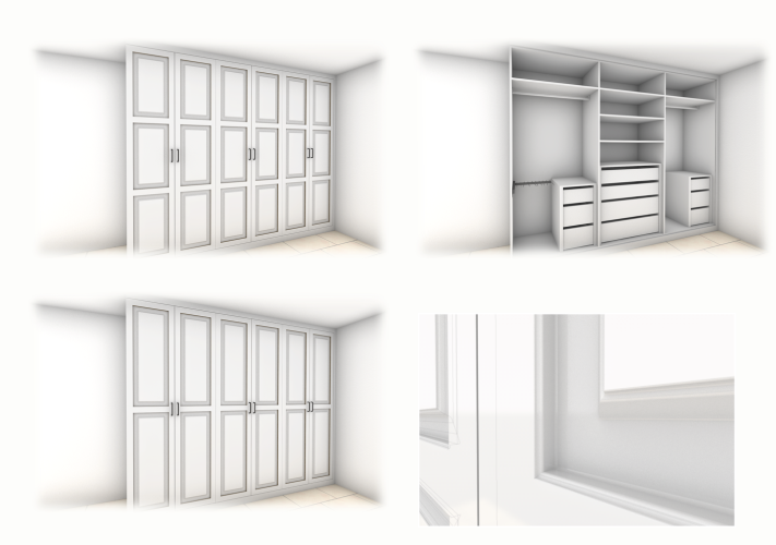
All is set to Renderstile "Moebel freistehend"
Panorama Export Setting: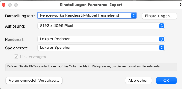
Here the panorama export with the same renderstile: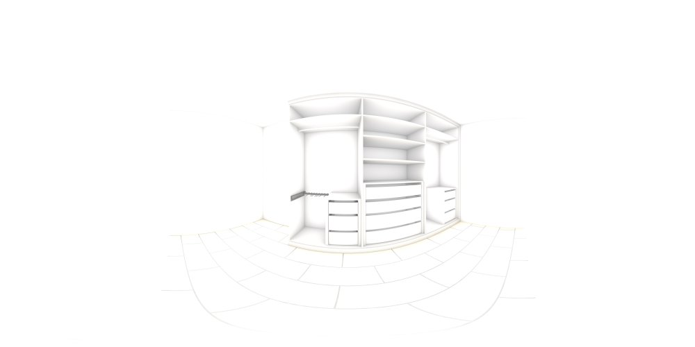
The Link to the panorama
https://cloud.vectorworks.net/links/11ece6958ee3d58291a90e8843f6c72d/
How it would be used: This panorama is exported Renderworks but with a renderstile with a darker hdri.
https://cloud.vectorworks.net/presentations/11ecc73b611af0e39a191233fa6cc30d/
File:
https://cloud.vectorworks.net/links/11ece69bcd28bbdaaf4c0e8843f6c72d/-
1
-
-
Hello
Also very interested in making visible the work of an algorithm.
I think it is possible by script to show the Objects created or manipulated by script. But a Marionette saves the view before the script runs and recovers it. Somehow this results in a different behavior from Marionette compared to a python script. I played around with this some time ago. The Attached Document shows a script that contains the same code as a Marionette. By executing the script the movement of rectangle is plotted on the screen.
For another example I putted every of the steps of the script on different layers. Then after the execution I batch-export the layers as pictures then combined into a movie with an external tool. Like this:
I can't find that example anymore but I think i just hardcoded an Object creation and a vs.SetParent to put it on a new Layer-
3
-
-
Well done!
-
1
-
-
Hi
You can use the "Get Item" to get an element of a list. Input 0 to get first Item. So 10th Item you get with input 9.

-
2
-
-
This looks like, the symbol was edited last while the design-layer had another layer scale thank the layer scale of the actual active layer.
Normally it helps co activate all, cut (cmd/ctrl. + X) and paste (cmd/ctrl + V). In this case it seems, the code attached to the add-node is broken.
I can correct it as follows:
1. cut and paste2. Double click and edit "less equal" and "greater equal"
3. Then the wires to the add node desapears and I reconnect again then it works.
I think there is still an issue which can corrupt Marionette scripts. If you insert a red symbol on a design-layer which have a different layer scale than the layer scale was active while the symbol was created.
-
As the concat node is, it converts the input to a string and then loop the character and adds them.
    #inputs
    stringIn = str(self.Params.stringIn.value)

    #script
    newString = ''
    for s in stringIn:
        newString = newString + s

    #outputs
    self.Params.stringOut.value = newString
I am not sure but I would expect from this node, it should do something like this:#inputs stringIn = self.Params.stringIn.value #script newString = '' for s in stringIn: newString = newString + str(s) #outputs self.Params.stringOut.value = newString
-
Hi
You want to attach a Text property on a Marionette Object and then inside the Script ask for the Text Properties attached to the Marionette PIO? I think if a Marionette Object can get some infos from the text menu, it would be possible.
You can handle the Parent PIO, but I do not see, that a Marionette can get some text Infos by the text menu. You could get the class of the Parent PIO and the Text Style of the Class as a workaround maybe. But directly the Text Style I think works not with a Marionette Object Node.
Here An example, if you get the text style of the parent PIO class.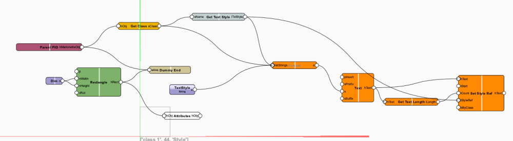
Side Note:
First Time I use concat node, it seems to convert the input list to a string instead of concat the input strings, which is somehow not what I would expect. It converts the List in a string first ...
-
1
-
-
- Popular Post
- Popular Post
Depending of the Skills and what the End-Result should be.
Even a Script with less parametric (width, depth, height) but with a lot of Graphical Details (rounded edges different materials, Fittings etc.) will give you a lot of Nodes by create every object by script. So when you start your script is pretty compact. At the end you want to add record formats, different surfaces, textures, colors, switching on of objects, replace handles etc. etc. So it can be your script if you start looks very different from what you really use at the End.
I think we could group some of different strategies. I show you here 4 different approaches for writing a Script with Marionette:
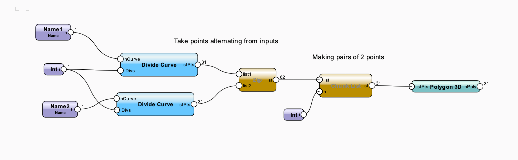
1. Geometric Strategy.
Like you would draw it manually maybe. While in Marionette this means if you need a middle Point you haveto draw an object or if you need a parallel contour you have to create it. Also geometrical could be we had a Node that calculates as example a parallel shape but do not draw an object. Here an example which do the job of ground-plate and foots Example:
Here are Rectangle is created and then a parallel contour to this rectangle the edge points of the contour are taken for the foot Objects. The Advantages of this would be, if you have a non rectangular shape it would still do the job.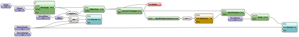
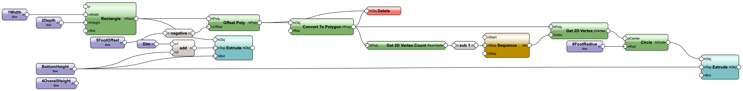
2. Calculation Strategy with native-Node-Math-Calculation.
This Means you would calculate the points first and then create the Objects at the resulting pre-calculated points. With "native-Node-Calculation" I mean, that every simple math calculation is created by nodes. This generally results in a lot of nodes but everything is directly visible. So for small stuff this is OK.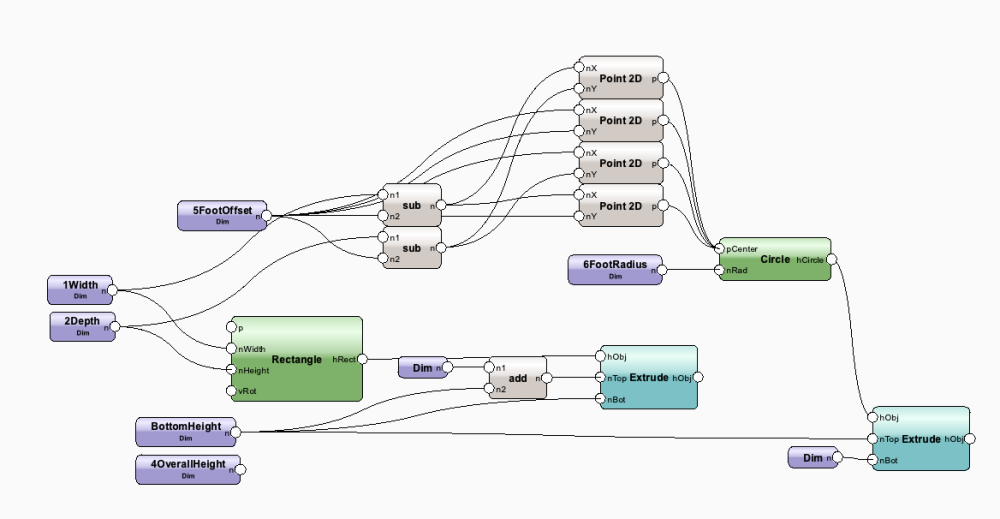
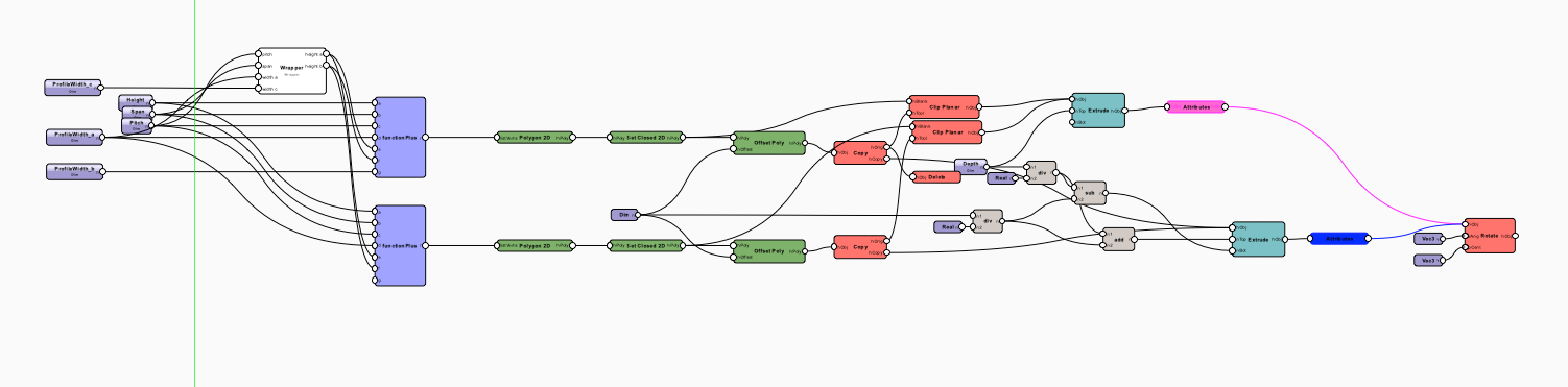
3. Hybrid technique by using function Nodes:
The technique from my example 2 can topple the Advantages of graphical Scripting to code-Scripting. Because a simple math like (a+b-c*2-25+1-2+a*4+a-5+a/2) is fast written by keyboard and need very much time to scripting node by node. Function Nodes can help a lot to optimize Marionette Workflows. While Standard-node-Library have one function node, I often use function2 or function4 (4 input). Look next, that example which does the same as Example 2 but without the math and Point nodes. The More calculations you need the more time you save with that workflow.
I wrote the formula over the Node. It need the same reflections (not really more brain) like example 2 but is more compact. The only special here is, that I create the points with the brackets instead with the nodes.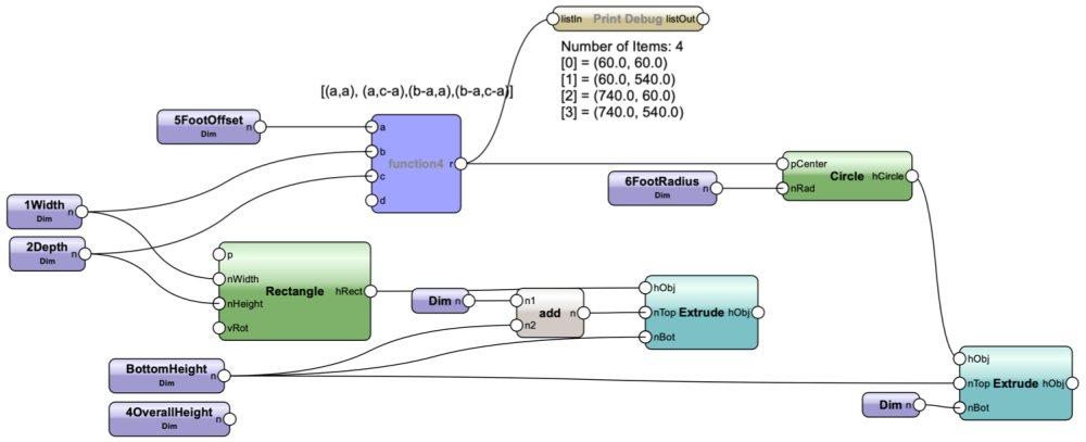
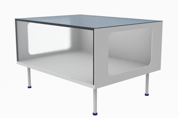
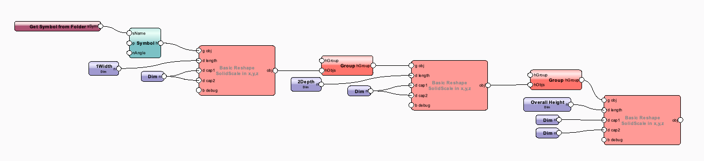
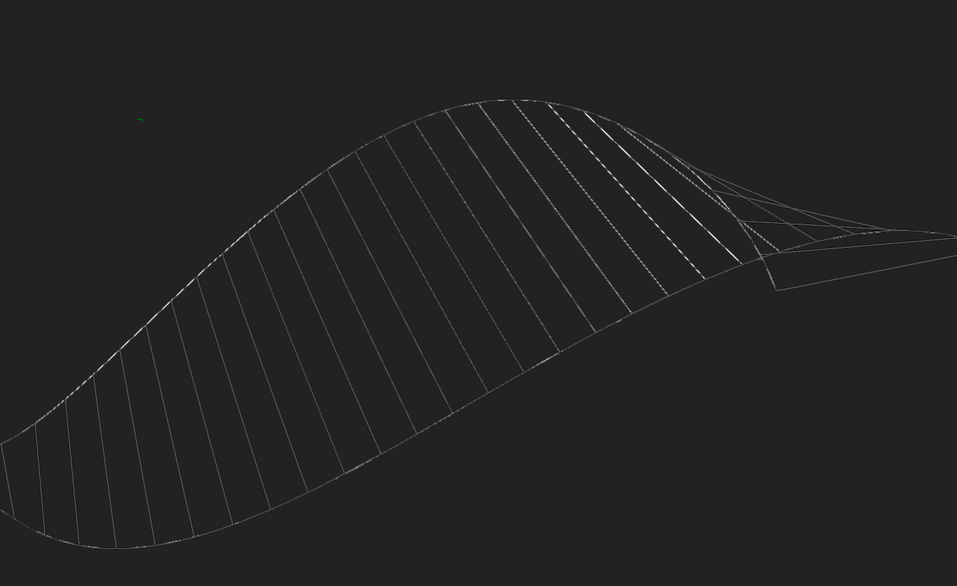
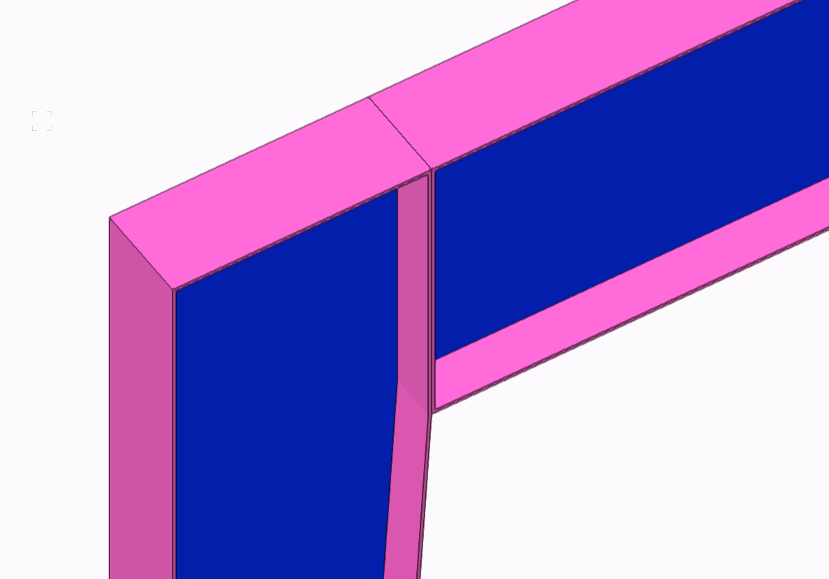
4. Using existing Geometry. If you have a simple parametric (width, depth, height as Example) and a high grade of Details of your geometry the workflow of scripting every object is getting not the best Option. There are Custom Nodes, which allows to handle existing Geometry instead of creating Geometry. Here an Example, which takes "prototype" Geometry of your Object and "reshape it" in x, y, and z direction. The big advantages is, that graphical Details you draw in your Object will not blow ob your network and also you can input different but similar types of your object (one with frame, one with plate backside, one with rectangular foots etc. etc.) without doing a new script.
Just a short picture of example #4. I just made some holes and profiles to the case. But the script is the same, no matter if more details are added. On the negative side, just half of the nodes are content of the standard-Library (It is not on me to change that).

If I have to create a quite simple parametric (like a showcase). I combine Strategy 3 and 4 for myself. So one part like the hull is maybe just x y z parametric. The other part are maybe panels and data or part list informations I script additionally. You can also combine something like in Strategy Example 4 with several x y z reshape operations and two different symbols.
I think maybe too much informations for a beginner but that example is pretty perfect to study the different scripting workflow. At the end it is matter of taste and what I like most on Vectorworks we have always the freedom to have our own taste.
I also learn always something new, If I see scripts from others. Even from beginners maybe think of something new which also old rabbits can absorb in their workflows.
-
7
-
 1
1
-
Hello
Welcome to the Marionette Forum. I think your script looks quite good. My workflow is often to first calculate all necessary points and data. After That I create the Objects. Also I use a lot of custom nodes to save number of nodes (Enhanced Rectangle, Function 2, BBox Enhanced) but this is not necessary per se.
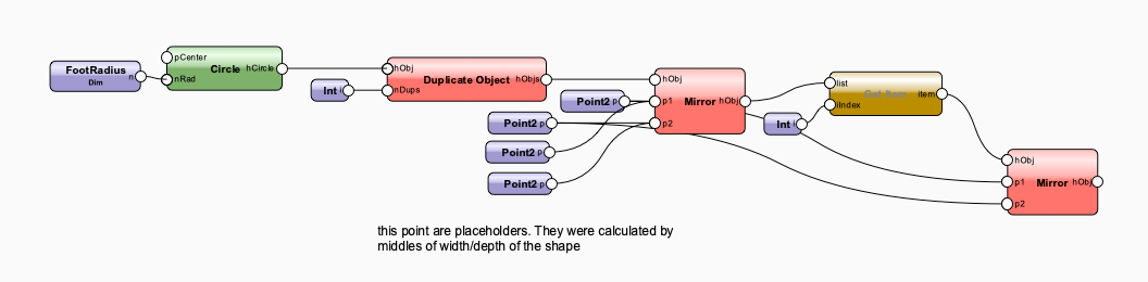
Creating Rectangle to find the corner point is something I would not do generally. Also Mirroring is not necessary, if your feeds are circles or squares.
To Mirror correctly you need one horizontal and one vertical axis. In your Script there is only one Axis. Also you need to mirror one Feed over a Diagonal Axis and if the shape is not a square, this had to be calculated. Or you Mirror at the Vertical Axis, then you mirror the resulting object along the horizontal axis. The Get Item in the Screenshot, gets the first second duplicate (top left) and mirror again along the vertical axis.
By the way, mirroring should work like this:
-
- Popular Post
-
5
-
tkinter could be installed with the Marionette python Modul importer. But at the Moment this maybe also not work out of the box. And by using tkinter I had negative effects resp. some functions maybe additional code to make it run in an embedded python.
Maybe off-topic. For Crossplatform Clipboard, this script could be used:
import math
import os
import subprocess

major, minor, maintenance, platform = vs.GetVersion()

text = 'Hello World'

def addToClipBoardWin(text):
	command = 'echo ' + text.strip() + ' | clip'
	os.system(command)

def addToClipBoardMac(text):
	process = subprocess.Popen('pbcopy', env={'LANG': 'en_US.UTF-8'}, stdin=subprocess.PIPE)
	process.communicate(text.encode('utf-8'))


if platform == 1:
	addToClipBoardMac(str(text))
else:
	addToClipBoardWin(str(text))
-
4
-
-
That little test works here. It seems the nested callback of the wiki-example is a little bit too ambitious.
vs.DSelectAll()

def resultCallback1():
	h1 = vs.FSActLayer()
	vs.DSelectAll()
	p1 = vs.GetSegPt1(h1)
	p2 = vs.GetSegPt2(h1)
	vs.Locus(p1)
	vs.Locus(p2)
vs.CallTool(-201, resultCallback1)
-
Hi
I just stumpled over that here:
https://developer.vectorworks.net/index.php/VS:CallTool
It seems, that CallTool is able to server a callback function. It is satisfying great to see every step of better python interaction with Vectorworks. Unfortunately it seems, that the example code on the developer Wiki does not work here. Anybody tried something already which is using that callback feature? -
Hello
I think the issue with the script that makes it slow is, that you loop the light devices and in that loop you give a search-request with ForEachObject. If you have many objects in your drawing a search-request over all objects in the Drawing could take maybe one second and if you have that 250 times in a loop it will take 250 seconds as example.
The better way in my opinion
1. Use ForEachObject just once on all Objects that could be your target light objects ()
2. Then loop all light devices from data (as you do)
3. Then do it as following:
if (isAvailable):
	lights = [] #name, handle
	def get_lights(h):
		n = vs.GetName(h)
		lights.append([n,h])

	c = "((PON='Lighting Device'))"
	vs.ForEachObject(get_lights, c)

	for p in data['LightingDevices']:
		uid = p['__UID']
		for light_name, h in lights: #loop through the found light objects in the drawing
			if light_name == uid:
				instrType = p['instrumentType']
				instrMode = p['fixtureMode']
				wattage = p['wattage']
				weight = p['weight']
				position = p['position']
				purpose = p['purpose']
				channel = p['channel']
				unitNumber = p['unitNumber']
				universeAdress = p['patch']
				circuitNumber = p['circuitNumber']
				circuitName = p['circuitName']
				dmxLine = p['dmxLine']
				dmxFootprint = p['dmxFootprint']
				deviceType = p['deviceType']
				color = p['color']
				template1 = p['template1']
				template2 = p['template2']
				user1 = p['userField1']
				user2 = p['userField2']
				user3 = p['userField3']
				user4 = p['userField4']
				user5 = p['userField5']
				user6 = p['userField6']
				className = p["class"]
				eachLight(h)
The loop in loop will be very fast. Much faster then the search-request (ForEach ...) inside a loop.
Untested code but I bet a beer this would do the job faster
-
2
-
-
Hi
It should be possible, to use the "Attributes"-Node to set fill pattern to 0. Connect it after your object and set it to Empty Fill. After That attach your colors. The Problem could be that the "Attributes" node replace also the line weight and line style. If that is a problem you can use the "function"-Node. And just paste vs.SetFPat(x, 0) in the input field.
-
Hi
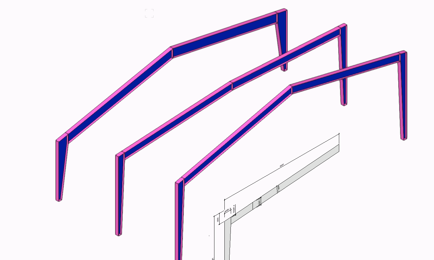
I think this object is between 2-40 hours to create. So I post without taking the order.
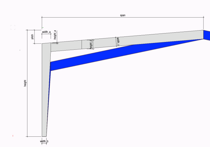
It depends on which level of Detail you really need (Material Thickness , drillings for screws etc.) I can give you or somebody else a start-assist and a possible workflow. A sketch, what pitch, height, span, base size exactly means were nice because it is a big part of the work to specificate exactly which values should be variable. It is about the work of 3 hours (but always the first 60% from something are done very fast. It would be enough if you do not need any screws and if the material thickness on all edges would be the same and if you need just the hull of the material not the single parts and how they exactly cutted in raw form (miter etc)).
Once more I ask myself, how it is possible to create exact Elements by using the non-metric-unit-system (just a gloss a place whenever I have the chance :-)

-
3
-
-
Hi
Marionette has his own function to deside (and with that if it should use a 3D Move, 3D Rotate or 2D Move, 2D Rotate etc.) if an object is planar or not. This concept has some limitations.
If you edit the code to this, the rotate node will work inside the PIO. Double click the node and delete the first line, then you can edit the code.
#planar = Marionette.Is2DObject(obj)
cx = center[0] - offset[0]
cy = center[1] - offset[1]
cz = center[2] - offset[2]
#if planar:
vs.HRotate(obj, (cx, cy), r[2])
#else:
#    vs.Set3DRot(obj, r[0], r[1], r[2], cx, cy, cz)
In this case, the Rotate-Node deside, that it wants to use the vs.Set3DRot() command to the symbol. which seems to work, if the symbols are on the layer. Inside the PIO it does not work. But this will not work, if the symbols are on screen plan. Inside the PIO the symbols are placed on a screen-plane like place (top plan view).
I think it is related to the different plane- and container-concepts that makes it very frittered and hard for one node to handle.
-
On 3/29/2022 at 1:06 PM, Sloader said:
it would be good to suppress the failure messages
Hello
Does it maybe work if you do something like this:try: vs.SetRField(h2,'Massing Model','2Ddisplay','Roof') #your code except: pass #or do someting like taggging the object as "too complexe" or do another function
Alternatively you can put something heavy on your enter key, while script is running.
-
1
-
 1
1
-
-
Hello
Chris solved his situation with putting the top/plan component on screen-plane and use set parent to move it into the symbol.
In the meantime I made an node for SetPlanar Ref. The includes Command (vs.Set2DComponentGroup) needs a group of screen-plane objects to work. So use the Set Planar Boolean and the group node for your geometry. For a hybrid symbol with 3D and top/plan the SetComponentGroup is not necessary. SetComponentGroup would need to set front, left, section views etc.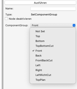
-
4
-
-
Hello
Same Issue here. It seems as soon as we have light from a HDRI this light is intensified by exporting a Panorama. I think most of users just exports the panorama without choosing the same Render-Style as the use in Vectorworks. Then the Result is Standard-RenderWorks with maybe no HDRI light attached and looks not too bright. -
Just read the initial post. "Workgroup folder"
OK, now it is getting interesting. It depends on platform you work and workgroup folder is stored in the system I think (plist or registry).
But I would not use this it is digging deep and it may not work anymore with newer versions etc. maybe hard to get it to work again. Also I did not checked if this is still working.
#Windows

import getpass
import shutil

HSFPath = vs.GetFPathName()
vs.AlrtDialog(HSFPath)
#Application	1
#User App Data	12
target = 'Users/dominiquecorpataux/Desktop'

from winreg import *
aReg = ConnectRegistry(None,HKEY_CURRENT_USER)
aKey = OpenKey(aReg, r"Software\Nemetschek\Vectorworks 24\General")
WGF_Path = QueryValueEx(aKey, "Workgroup Folder 0")
#vs.Message(WGF_Path[0])
target = WGF_Path[0]

vs.AlrtDialog(str(target))


#on mac

import plistlib
#MacFile = 'Users/dominiquecorpataux/Library/Preferences/net.nemetschek.vectorworks.2019.plist'
pl = {}
with open(file, 'rb') as fp:
    pl = plistlib.load(fp)

vs.AlrtDialog(str(pl.get("NNA Workgroup Folders")))
vs.AlrtDialog(pl["NNA Workgroup Folders"])


3D Fillet??
in Vectorscript
Posted
Thanks for input Larry and Pat.
ConvertToNURBS can't put several segments together. If that is possible it would also not be needed to draw planar polylines and rotate them into the 3D Plane. I have corner points and control points already calculated and can directly draw a NURBS in 3D. It seems, that the hurdle is, that one segment of NURBS can only handle one type of vertex. Rounded vertex or edge vertex. every time we have an unrounded edge we have to create a new segment which we can't combine together. Minimum not in an easy way. What I also thought about is, that maybe the NURBS Curve with several NURBS internally is a different object as a single segment.
What i maybe will try later:
1. Creating the object with different segments seems to be an attractive and proper solution. Also additionally the Level of detail for a fitting can be implemented here.
2. Menu Command compose making to work inside a Marionette PIO. But for that think I have to parent the Object on a layer then compose it and parent it back into the PIO. Which could work but is somehow ass-backward (Translation from "von hinten durch die Brust ins Auge" ?).